EP0338339B1 - Window for switchgear cabinet or module carrier - Google Patents
Window for switchgear cabinet or module carrier Download PDFInfo
- Publication number
- EP0338339B1 EP0338339B1 EP89106094A EP89106094A EP0338339B1 EP 0338339 B1 EP0338339 B1 EP 0338339B1 EP 89106094 A EP89106094 A EP 89106094A EP 89106094 A EP89106094 A EP 89106094A EP 0338339 B1 EP0338339 B1 EP 0338339B1
- Authority
- EP
- European Patent Office
- Prior art keywords
- profile portion
- inspection window
- window according
- plate
- covering profile
- Prior art date
- Legal status (The legal status is an assumption and is not a legal conclusion. Google has not performed a legal analysis and makes no representation as to the accuracy of the status listed.)
- Expired - Lifetime
Links
Images

Classifications
-
- H—ELECTRICITY
- H02—GENERATION; CONVERSION OR DISTRIBUTION OF ELECTRIC POWER
- H02B—BOARDS, SUBSTATIONS OR SWITCHING ARRANGEMENTS FOR THE SUPPLY OR DISTRIBUTION OF ELECTRIC POWER
- H02B1/00—Frameworks, boards, panels, desks, casings; Details of substations or switching arrangements
- H02B1/26—Casings; Parts thereof or accessories therefor
- H02B1/30—Cabinet-type casings; Parts thereof or accessories therefor
- H02B1/306—Accessories, e.g. windows
Definitions
- the invention relates to a viewing window for an opening of a control cabinet or subrack with a U-shaped transparent pane made of a front plate and two side plates, which is connected to frame parts at least on the two end faces. (See DE-A-3 144 131)
- Such viewing windows are used to cover openings on a control cabinet or the opening on the front of a rack so that the components located in the area of the opening, such as display and operating elements, can be viewed.
- the viewing window can be firmly connected to the wall surrounding the opening or be articulated on this wall via a frame part, while the other frame part carries a closure with which the closed position of the viewing window can be locked.
- complicated and expensive frame parts are required for the viewing window, which also require considerable parts and assembly effort.
- the frame parts are each composed of a connecting profile section and a U-shaped cover profile section which can be snapped onto it, the lengths of which correspond to the clear distance between the side plates of the pane, that the connecting profile section has a receiving groove for plugging onto the front side of the front plate the disc has that the connecting section and the snapped cover profile section form a continuous longitudinal chamber and that corner pieces are provided with a receiving groove on the end faces of the side plates of the disc, which protrude into the longitudinal chamber of the frame parts with retaining lugs and are held therein.
- connecting profile sections need to be connected to the front plate of the pane.
- connection profile section and the cover profile section can be cut to length from a profile strand in the desired length, the adaptation to different sizes of the viewing window is not a problem.
- the corner pieces remain unchanged.
- the Ausgstaltung is made so that the connecting profile section consists of a base plate which carries on one long side the receiving groove formed by bends, that the opening of the receiving groove lies approximately in the plane of the base plate, and that the base plate in the area of the other long side a molded Has detent web with detent at the free end.
- a cover profile section which can be locked quickly and easily with this connecting profile section is characterized in that it overlaps with one side leg the angling of the receiving groove lying on the front of the front plate of the pane and engages behind its end face with a retaining web and in that the other side leg of the cover profile section has a snap-in receptacle for the latching approach of the locking web of the connecting profile section.
- the locking end position is determined by the fact that the cover profile section has an integrally formed support web on its inside, which is supported on the base bend of the receiving groove of the connection profile section and that the side leg with the locking receptacle of the cover profile section after locking with the locking web of the connection section on the base plate of the Supporting section section supports.
- a further embodiment it is provided from an aesthetic point of view that the front of the Disc facing edge between the side leg and the base leg of the cover profile section is chamfered and that this chamfer continues over the attached corner pieces. So that the beveled shape continues over the corner pieces, a further embodiment provides that the corner pieces on the sides facing the outside of the base leg of the cover profile section join flush and taper over the beveled transition area of the cover profile section and are bevelled accordingly.
- the cover profile section in the region of its base leg is extended beyond the side leg with the snap-in receptacle and has a bore, then an attachment option for hinges is created.
- a flush termination of the frame parts towards the pane is achieved in that the retaining web of the side leg of the cover profile section is flush with the inside of the base plate of the connection profile section facing away from the latching web after the cover profile section has snapped on.
- This conclusion is achieved up to the free edges of the side plates of the pane in that the base plate of the connecting profile section is extended beyond the latching web and over the extension with the through bore of the base leg of the cover profile section to the free edge of the side plates of the pane and is flush with it completes.
- the cover profile section does not always have to have a width which corresponds to the width of the side plates if the viewing window extends partially into the opening of the control cabinet or of the subrack.
- a further embodiment provides for aesthetic reasons that the outside of the base leg of the cover profile section has longitudinal grooves at regular intervals.
- the configuration is advantageously made in such a way that in the base leg of the cover profile section of the one frame part the closure is inserted, which has a locking cylinder with a locking bolt, that the locking bolt cooperates with a locking bolt fixed in a side wall delimiting the opening in such a way that in the extension of the base leg of the cover profile section of the other frame part bearing bolts for angular hinge parts are introduced, which are thus pivotally mounted on the cover profile section, and that the hinge parts are attached to a side wall delimiting the opening.
- the closure is inserted into a recess which can be introduced at any point on the base leg of the cover profile section.
- the hinge parts can be articulated in a simple manner on the cover profile section.
- the extension of the base leg of the cover profile section in the area of the hinges can also be left out if one wants to achieve a large swivel angle for the viewing window.
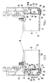
- FIG. 1 only the part of the subrack 15 around the front opening 16 is shown. It can be seen that the corner edges of the subrack 15 are chamfered.
- the vertically directed frame part is shown in the assembled position and attached to the pane 10, only the cover profile section 22 and the two corner pieces 30 being recognizable on the U-shaped, transparent pane 10.
- the disc 10 is formed by the front plate 11 and the two side plates 12 and 13, which are integrally connected to one another.
- the frame part is not yet attached to the left end face 14 of the pane 10. However, the parts are shown in an exploded view, which are required for the frame part.
- the connection profile section 17 is connected to the end face of the disk 10.
- the connecting profile section 17 is cut to a length which corresponds to the clear distance between the side plates 12 and 13 of the disc 10.
- the base plate 18 of the connecting profile section 17 faces the front Longitudinal edge on the receiving groove 20, which is formed by corresponding bends.
- the latching web 19 is molded onto the base plate 18 and has a continuous latching shoulder towards the associated long side.
- the base plate 18 is plugged with the receiving groove 20 onto the end face 14 of the front plate 11, whereby it is inserted into the area between the two side plates 12 and 13 and with the part extended beyond the latching web 19, flush with the free edges of the side plates 12 and 13 of the disc 10 completes.
- the front plate 11 can be fixed by gluing in the receiving groove 20 of the connecting profile section 17.
- the front plate 11 and the bends of the receiving groove 20 can also have aligned bores through which the two parts can be screwed or pinned together. If the connecting profile section 17 is fixed on the pane 10, then the corner pieces 30 are plugged onto the end faces 14 of the side plates 12 and 13. The sides of the corner pieces 30 facing the side plates 12 and 13 of the pane 10 likewise have receiving grooves for the side plates 12 and 13 which, as can be seen from FIG. 1, also extend to the free edges of the side plates 12 and 13. The corner pieces 30 plugged onto the side plates 12 and 13 are thus already held in the longitudinal direction of the connecting profile section 17. The U-shaped cover profile section 22 is then snapped onto the connection profile section 17.
- the front side leg 23 of the same runs out into the inwardly directed retaining web 24, which is placed on the end face of the outer bend 21 of the receiving groove 20 of the connecting profile section 17. Then the inner side leg 25 of the cover profile section 22 is snapped onto the latching web 19 of the connection profile section 17, as indicated in FIG. 2. The rest of the way externally projecting latching projection of the latching web 19 into the latching receptacle 26 which is continuous on the inside of the inner side leg 25.
- the continuous longitudinal chamber 37 (FIG. 4) is thus completed between the connection profile section 17 and the cover profile section 22.
- retaining lugs 32 are formed, which protrude into this longitudinal chamber 37 and are captively held therein transversely to the frame part after the locking of the connecting profile section 17 and cover profile section 22.
- the support web 28, which is formed on the inside of the base leg of the cover profile section 22, is supported on the base bending of the receiving groove 20 of the connection profile section 17.
- the inner side leg 25 also limits the snap-on movement of the cover profile section 22 by contacting the outside of the base plate 18 of the connecting profile section 17.
- the transition from the outer side leg 23 to the base leg of the cover profile section 22 is beveled, as the section according to FIG. 3 clearly shows. Therefore, the adjoining side 43 of the corner pieces 30 is also beveled accordingly.
- the side of the corner pieces 30 which is initially flush with the outside of the base leg of the cover profile section 22 merges into beveled transition sections 42 which, in the closed position of the viewing window, connect flush to the beveled corner edges of the subrack 15.
- the closure is introduced into the base leg of the cover profile section 22, which is provided on its outside with a number of longitudinally aligned grooves which are introduced at regular intervals.
- the cylinder lock 39 is inserted, which is inserted into the lock plate 27 and protrudes into the longitudinal chamber 37 of the frame part and carries the rotary latch 40 there.
- the rotary latch 40 is led out of the longitudinal chamber 37 via a recess in the inner side leg 25 of the cover profile section 22 and cooperates with the locking bolt 41, which is fixed to the side wall 33 of the subrack delimiting the opening 16.
- the articulation side of the viewing window is shown in section.
- the extension of the base leg of the cover profile section 22 can have bores 29 for hinge bolts 38 made at least in the two end sections. However, the bore 29 can also be continuous.
- Angular hinges 36 are fastened to the facing side wall 34 of the subrack, as the fastening point 35 indicates. These hinges 36 protrude into recesses of the extension of the base leg of the cover profile section 22 and carry aligned holes with the holes 29, so that the hinge bolts 38 inserted into the holes establish the articulated connection between the hinges 36 and the cover profile section 22 and thus the frame part with the viewing window can.
Abstract
Description
Die Erfindung betrifft ein Sichtfenster für eine Öffnung eines Schaltschrankes oder Baugruppenträgers mit einer U-förmigen durchsichtigen Scheibe aus Frontplatte und zwei Seitenplatten, die zumindest an den beiden Stirnseiten mit Rahmenteilen verbunden ist. (Siehe DE-A-3 144 131)The invention relates to a viewing window for an opening of a control cabinet or subrack with a U-shaped transparent pane made of a front plate and two side plates, which is connected to frame parts at least on the two end faces. (See DE-A-3 144 131)
Derartige Sichtfenster werden dazu verwendet, Öffnungen an einem Schaltschrank oder die Öffnung an der Vorderseite eines Baugruppenträgers so abzudecken, daß die im Bereich der Öffnung liegenden Bauteile, wie Anzeige- und Bedienungselemente, eingesehen werden können. Dabei kann das Sichtfenster fest mit der die Öffnung umschließenden Wand verbunden sein oder an dieser Wand über ein Rahmenteil angelenkt sein, während das andere Rahmenteil einen Verschluß trägt, mit dem die Schließstellung des Sichtfensters arretiert werden kann. Gerade bei der letztgenannten Ausgestaltung des Sichtfensters sind komplizierte und teuere Rahmenteile für das Sichtfenster erforderlich, die zudem einen erheblichen Teile- und Montageaufwand erfordern.Such viewing windows are used to cover openings on a control cabinet or the opening on the front of a rack so that the components located in the area of the opening, such as display and operating elements, can be viewed. The viewing window can be firmly connected to the wall surrounding the opening or be articulated on this wall via a frame part, while the other frame part carries a closure with which the closed position of the viewing window can be locked. Especially with the latter design of the viewing window, complicated and expensive frame parts are required for the viewing window, which also require considerable parts and assembly effort.
Es ist Aufgabe der Erfindung, für ein Sichtfenster der eingangs erwähnten Art Rahmenteile zu schaffen, die sowohl für die feste als auch die angelenkte Verbindung mit einem Schaltschrank oder einem Baugruppenträger verwendbar sind, einfache Teile umfassen, die auch an unterschiedliche Größen des Sichtfensters anpaßbar sind und schnell und leicht an der Scheibe des Sichtfensters angebracht werden können.It is an object of the invention to provide frame parts for a viewing window of the type mentioned at the outset which can be used for both the fixed and the articulated connection to a control cabinet or a subrack, comprise simple parts which can also be adapted to different sizes of the viewing window and can be quickly and easily attached to the window pane.
Diese Aufgabe wird nach der Erfindung dadurch gelöst, daß die Rahmenteile jeweils aus einem Anschlußprofilabschnitt und einem darauf aufrastbaren U-förmigen Abdeckprofilabschnitt zusammengesetzt sind, deren Längen dem lichten Abstand der Seitenplatten der Scheibe entsprechen, daß der Anschlußprofilabschnitt eine Aufnahmenut zum Aufstecken auf die Stirnseite der Frontplatte der Scheibe aufweist, daß der Anschlußabschnitt und der aufgerastete Abdeckprofilabschnitt eine durchgehende Längskammer bilden und daß auf die Stirnseiten der Seitenplatten der Scheibe mit einer Aufnahmenut versehene Eckstücke aufgesteckt sind, die mit Halteansätzen in die Längskammer der Rahmenteile ragen und darin gehalten sind.This object is achieved according to the invention in that the frame parts are each composed of a connecting profile section and a U-shaped cover profile section which can be snapped onto it, the lengths of which correspond to the clear distance between the side plates of the pane, that the connecting profile section has a receiving groove for plugging onto the front side of the front plate the disc has that the connecting section and the snapped cover profile section form a continuous longitudinal chamber and that corner pieces are provided with a receiving groove on the end faces of the side plates of the disc, which protrude into the longitudinal chamber of the frame parts with retaining lugs and are held therein.
Bei dieser Ausgestaltung brauchen nur die Anschlußprofilabschnitte mit der Frontplatte der Scheibe verbunden zu werden. Dies kann einmal dadurch erfolgen, daß die Anschlußprofilabschnitte im Bereich ihrer Aufnahmenut mit der Frontplatte der Scheibe verklebt sind und zum anderen dadurch, daß die Anschlußprofilabschnitte im Bereich ihrer Aufnahmenut mit Bohrungen versehen sind, die mit Bohrungen in der Frontplatte der Scheibe fluchten, und daß die Frontplatte der Scheibe und der Anschlußprofilabschnitt über die fluchtenden Bohrungen miteinander verbunden, vorzugsweise verstiftet oder verschraubt sind. Dann werden die Eckstücke auf die Stirnseiten der Seitenplatten der Scheibe aufgesteckt und die Abdeckprofilabschnitte auf die Anschlußprofilabschnitte aufgerastet. Dabei werden dann die Eckstücke unverlierbar gehalten, da die Halteansätze in der vervollständigten Längskammer des Rahmenteils quer zu den Rahmenteilen festgehalten werden und die Seitenplatten der Scheibe, die in den Aufnahmenuten der Eckstücke gehalten sind, ein Entfernen der Eckstücke in Längsrichtung der Rahmenteile verhindern. Da der Anschlußprofilabschnitt und der Abdeckprofilabschnitt von einem Profilstrang in der gewünschten Länge abgelängt werden können, ist die Anpassung an unterschiedliche Größen des Sichtfensters kein Problem. Die Eckstücke bleiben dabei unverändert.With this configuration, only the connecting profile sections need to be connected to the front plate of the pane. This can be done on the one hand by the fact that the connecting profile sections are glued to the front plate of the disk in the area of their receiving groove and on the other hand that the connecting profile sections are provided in the area of their receiving groove with bores that are aligned with bores in the front plate of the disk, and that Front plate of the disc and the connecting profile section are connected to one another via the aligned bores, preferably pinned or screwed. Then the corner pieces are plugged onto the end faces of the side plates of the pane and the cover profile sections are snapped onto the connection profile sections. The corner pieces are then held captive, since the retaining lugs are held transversely to the frame parts in the completed longitudinal chamber of the frame part and the side plates of the disc, which are held in the receiving grooves of the corner pieces, prevent removal of the corner pieces in the longitudinal direction of the frame parts. Because the connection profile section and the cover profile section can be cut to length from a profile strand in the desired length, the adaptation to different sizes of the viewing window is not a problem. The corner pieces remain unchanged.
Die Ausgstaltung ist dabei so vorgenommen, daß der Anschlußprofilabschnitt aus einer Grundplatte besteht, die an einer Längsseite die durch Abwinkelungen gebildete Aufnahmenut trägt, daß die Öffnung der Aufnahmenut etwa in der Ebene der Grundplatte liegt, und daß die Grundplatte im Bereich der anderen Längsseite einen angeformten Raststeg mit Rastansatz am freien Ende aufweist.The Ausgstaltung is made so that the connecting profile section consists of a base plate which carries on one long side the receiving groove formed by bends, that the opening of the receiving groove lies approximately in the plane of the base plate, and that the base plate in the area of the other long side a molded Has detent web with detent at the free end.
Ein mit diesem Anschlußprofilabschnitt schnell und leicht verrastbarer Abdeckprofilabschnitt ist dadurch gekennzeichnet, daß er mit einem Seitenschenkel die auf die Vorderseite der Frontplatte der Scheibe liegende Abwinkelung der Aufnahmenut übergreift und mit einem Haltesteg dessen Stirnseite hintergreift und daß der andere Seitenschenkel des Abdeckprofilabschnittes eine Rastaufnahme für den Rastansatz des Raststeges des Anschlußprofilabschnittes aufweist.A cover profile section which can be locked quickly and easily with this connecting profile section is characterized in that it overlaps with one side leg the angling of the receiving groove lying on the front of the front plate of the pane and engages behind its end face with a retaining web and in that the other side leg of the cover profile section has a snap-in receptacle for the latching approach of the locking web of the connecting profile section.
Die Rastendstellung wird dabei dadurch festgelegt, daß der Abdeckprofilabschnitt auf seiner Innenseite einen angeformten Stützsteg aufweist, der sich auf der Basisabwinkelung der Aufnahmenut des Anschlußprofilabschnittes abstützt und daß sich der Seitenschenkel mit der Rastaufnahme des Abdeckprofilabschnittes nach dem Verrasten mit dem Raststeg des Anschlußabschnittes an der Grundplatte des Anschlußprofilabschnittes abstützt.The locking end position is determined by the fact that the cover profile section has an integrally formed support web on its inside, which is supported on the base bend of the receiving groove of the connection profile section and that the side leg with the locking receptacle of the cover profile section after locking with the locking web of the connection section on the base plate of the Supporting section section supports.
Nach einer weiteren Ausgestaltung ist aus ästhetischen Gesichtspunkten vorgesehen, daß die der Vorderseite der Scheibe zugekehrte Kante zwischen dem Seitenschenkel und den Basisschenkel des Abdeckprofilabschnittes abgeschrägt ist und daß sich diese Abschrägung über die angebrachten Eckstücke fortsetzt. Damit sich die abgeschrägte Form auch über die Eckstücke fortsetzt, sieht eine weitere Ausgestaltung vor, daß die Eckstücke auf den der Außenseite des Basisschenkels des Abdeckprofilabschnittes zugekehrten Seiten sich bündig anschließen und sich über den abgeschrägten Übergangsbereich des Abdeckprofilabschnittes verjüngen und entsprechend abgeschrägt sind.According to a further embodiment, it is provided from an aesthetic point of view that the front of the Disc facing edge between the side leg and the base leg of the cover profile section is chamfered and that this chamfer continues over the attached corner pieces. So that the beveled shape continues over the corner pieces, a further embodiment provides that the corner pieces on the sides facing the outside of the base leg of the cover profile section join flush and taper over the beveled transition area of the cover profile section and are bevelled accordingly.
Ist nach einer weiteren Ausgestaltung vorgesehen, daß der Abdeckprofilabschnitt im Bereich seines Basisschenkels über den Seitenschenkel mit der Rastaufnahme hinaus verlängert ist und eine Bohrung aufweist, dann ist eine Anbringungsmöglichkeit für Scharniere geschaffen.If, according to a further embodiment, it is provided that the cover profile section in the region of its base leg is extended beyond the side leg with the snap-in receptacle and has a bore, then an attachment option for hinges is created.
Ein bündiger Abschluß der Rahmenteile zur Scheibe hin wird dadurch erreicht, daß der Haltesteg des Seitenschenkels des Abdeckprofilabschnittes nach dem Aufrasten des Abdeckprofilabschnittes auf den Anschlußprofilabschnitt bündig mit der dem Raststeg abgekehrten Innenseite der Grundplatte des Anschlußprofilabschnittes abschließt. Dieser Abschluß wird bis zu den freien Kanten der Seitenplatten der Scheibe dadurch erreicht, daß die Grundplatte des Anschlußprofilabschnittes über den Raststeg und über die Verlängerung mit der durchgehenden Bohrung des Basisschenkels des Abdeckprofilabschnittes hinaus bis zum freien Rand der Seitenplatten der Scheibe verlängert ist und mit diesem bündig abschließt. Der Abdeckprofilabschnitt braucht nicht immer eine Breite aufzuweisen, die der Breite der Seitenplatten entspricht, wenn sich das Sichtfenster zum Teil in die Öffnung des Schaltschrankes oder des Baugruppenträgers hinein erstreckt.A flush termination of the frame parts towards the pane is achieved in that the retaining web of the side leg of the cover profile section is flush with the inside of the base plate of the connection profile section facing away from the latching web after the cover profile section has snapped on. This conclusion is achieved up to the free edges of the side plates of the pane in that the base plate of the connecting profile section is extended beyond the latching web and over the extension with the through bore of the base leg of the cover profile section to the free edge of the side plates of the pane and is flush with it completes. The cover profile section does not always have to have a width which corresponds to the width of the side plates if the viewing window extends partially into the opening of the control cabinet or of the subrack.
Eine weitere Ausgestaltung sieht aus ästhetischen Gründen vor, daß die Außenseite des Basisschenkels des Abdeckprofilabschnittes in gleichmäßigen Abständen längsgerichtete Nuten aufweist.A further embodiment provides for aesthetic reasons that the outside of the base leg of the cover profile section has longitudinal grooves at regular intervals.
Bei einem angelenkten Sichtfenster ist die Ausgestaltung in vorteilhafter Weise so getroffen, daß in den Basisschenkel des Abdeckprofilabschnittes des einen Rahmenteils der Verschluß eingesetzt ist, der einen Schließzylinder mit Drehriegel aufweist, daß der Drehriegel mit einem in einer die Öffnung begrenzenden Seitenwand festgelegten Schließbolzen zusammenarbeitet, daß in der Verlängerung des Basisschenkels des Abdeckprofilabschnittes des anderen Rahmenteils Lagerbolzen für winkelförmige Scharnierteile eingebracht sind, die damit schwenkbar an dem Abdeckprofilabschnitt gelagert sind, und daß die Scharnierteile an einer die Öffnung begrenzenden Seitenwand befestigt sind. Der Verschluß wird dabei in eine Ausnehmung eingesetzt, die an jeder beliebigen Stelle des Basisschenkels des Abdeckprofilabschnittes eingebracht werden kann. Ist die Bohrung in die Endabschnitte der Verlängerung des Basisschenkels eingebracht, dann lassen sich die Scharnierteile auf einfache Weise an dem Abdeckprofilabschnitt anlenken. Dabei kann die Verlängerung des Basisschenkels des Abdeckprofilabschnittes im Bereich der Scharniere auch ausgespart sein, wenn man einen großen Schwenkwinkel für das Sichtfenster erreichen will.In the case of a hinged viewing window, the configuration is advantageously made in such a way that in the base leg of the cover profile section of the one frame part the closure is inserted, which has a locking cylinder with a locking bolt, that the locking bolt cooperates with a locking bolt fixed in a side wall delimiting the opening in such a way that in the extension of the base leg of the cover profile section of the other frame part bearing bolts for angular hinge parts are introduced, which are thus pivotally mounted on the cover profile section, and that the hinge parts are attached to a side wall delimiting the opening. The closure is inserted into a recess which can be introduced at any point on the base leg of the cover profile section. If the bore is made in the end sections of the extension of the base leg, then the hinge parts can be articulated in a simple manner on the cover profile section. The extension of the base leg of the cover profile section in the area of the hinges can also be left out if one wants to achieve a large swivel angle for the viewing window.
Die Erfindung wird anhand eines in den Zeichnungen dargestellten Ausführungsbeispiels näher erläutert. Es zeigt:
- Fig. 1 in perspektivischer Ansicht ein an einem Baugruppenträger angelenktes Sichtfenster, wobei auf der Schließseite das Rahmenteil mit den einzelnen Teilen in Explosionsdarstellung wiedergegeben ist,
- Fig. 2 eine Teilansicht, die den Rastvorgang zwischen dem Abdeckprofilabschnitt und dem Anschlußprofilabschnitt wiedergibt,
- Fig. 3 im Querschnitt die Schließseite des Sichtfensters in der Schließstellung des Verschlusses und
- Fig. 4 im Querschnitt die Anlenkseite des Sichtfensters ebenfalls in der Schließstellung.
- Fig. 1 is a perspective view of a viewing window articulated on a subrack, wherein on the closing part shows the frame part with the individual parts in an exploded view,
- 2 is a partial view showing the locking process between the cover profile section and the connection profile section,
- Fig. 3 in cross section the closing side of the window in the closed position of the closure and
- Fig. 4 in cross section the hinged side of the window also in the closed position.
In der Fig. 1 ist von dem Baugruppenträger 15 nur der Teil um die vorderseitige Öffnung 16 gezeigt. Dabei ist zu erkennen, daß die Eckkanten des Baugruppenträgers 15 abgeschrägt sind. Auf der Anlenkseite ist das vertikal gerichtete Rahmenteil in der zusammengesetzten und an der Scheibe 10 angebrachten Stellung gezeigt, wobei nur noch der Abdeckprofilabschnitt 22 und die beiden Eckstücke 30 an der U-förmigen, durchsichtigen Scheibe 10 erkennbar sind. Die Scheibe 10 wird durch die Frontplatte 11 und die beiden Seitenplatten 12 und 13 gebildet, die einstückig miteinander verbunden sind. An der linken Stirnseite 14 der Scheibe 10 ist das Rahmenteil noch nicht angebracht. Es sind jedoch die Teile in Explosionsdarstellung gezeigt, die für das Rahmenteil erforderlich sind. Zuerst wird der Anschlußprofilabschnitt 17 mit der Stirnseite der Scheibe 10 verbunden. Der Anschlußprofilabschnitt 17 ist in einer Länge abgelängt, die dem lichten Abstand der Seitenplatten 12 und 13 der Scheibe 10 entspricht. Die Grundplatte 18 des Anschlußprofilabschnittes 17 weist an der vorderen Längskante die Aufnahmenut 20 auf, die durch entsprechende Abwinkelungen gebildet ist. Im Bereich der anderen Längsseite ist an die Grundplatte 18 der Raststeg 19 angeformt, der zur zugeordneten Längsseite hin einen durchgehenden Rastansatz aufweist. Die Grundplatte 18 wird mit der Aufnahmenut 20 auf die Stirnseite 14 der Frontplatte 11 aufgesteckt, wobei sie in den Bereich zwischen die beiden Seitenplatten 12 und 13 eingeführt wird und mit dem über den Raststeg 19 hinaus verlängerten Teil bündig mit den freien Kanten der Seitenplatten 12 und 13 der Scheibe 10 abschließt. Die Frontplatte 11 kann dabei durch Verkleben in der Aufnahmenut 20 des Anschlußprofilabschnittes 17 festgelegt sein. Die Frontplatte 11 und die Abwinkelungen der Aufnahmenut 20 können auch fluchtende Bohrungen aufweisen, über die beide Teile miteinander verschraubt oder verstiftet werden können. Ist der Anschlußprofilabschnitt 17 an der Scheibe 10 festgelegt, dann werden die Eckstücke 30 auf die Stirnseiten 14 der Seitenplatten 12 und 13 aufgesteckt. Die den Seitenplatten 12 und 13 der Scheibe 10 zugekehrten Seiten der Eckstücke 30 tragen ebenfalls Aufnahmenuten für die Seitenplatten 12 und 13, die wie aus Fig. 1 zu entnehmen ist, ebenfalls bis zu den freien Kanten der Seitenplatten 12 und 13 reichen. Die auf die Seitenplatten 12 und 13 aufgesteckten Eckstücke 30 sind in Längsrichtung des Anschlußprofilabschnittes 17 damit schon gehalten. Auf den Anschlußprofilabschnitt 17 wird dann der U-förmige Abdeckprofilabschnitt 22 aufgerastet. Der vordere Seitenschenkel 23 desselben läuft in den nach innen gerichteten Haltesteg 24 aus, der auf die Stirnseite der äußeren Abwinkelung 21 der Aufnahmenut 20 des Anschlußprofilabschnittes 17 aufgesetzt wird. Dann wird der innere Seitenschenkel 25 des Abdeckprofilabschnittes 22 auf den Raststeg 19 des Anschlußprofilabschnittes 17 aufgerastet, wie Fig. 2 andeutet. Dabei rastet der nach außen abstehende Rastansatz des Raststeges 19 in die auf der Innenseite des inneren Seitenschenkels 25 durchgehende Rastaufnahme 26 ein. Damit wird zwischen dem Anschlußprofilabschnitt 17 und dem Abdeckprofilabschnitt 22 die durchgehende Längskammer 37 (Fig. 4) vervollständigt. An den Eckstücken 30 sind Halteansätze 32 angeformt, die in diese Längskammer 37 ragen und nach dem Verrasten von Anschlußprofilabschnitt 17 und Abdeckprofilabschnitt 22 darin quer zum Rahmenteil unverlierbar gehalten sind.In FIG. 1, only the part of the
Wie der Schnitt nach Fig. 3 zeigt, stützt sich nach dem Verrasten der Stützsteg 28, der auf der Innenseite des Basisschenkels des Abdeckprofilabschnittes 22 angeformt ist, auf der Basisabwinkelung der Aufnahmenut 20 des Anschlußprofilabschnittes 17 ab. Auch der innere Seitenschenkel 25 begrenzt durch Anlage an der Außenseite der Grundplatte 18 des Anschlußprofilabschnittes 17 die Aufrastbewegung des Abdeckprofilabschnittes 22. Der Übergang von dem äußeren Seitenschenkel 23 zum Basisschenkel des Abdeckprofilabschnittes 22 ist abgeschrägt, wie der Schnitt nach Fig. 3 deutlich zeigt. Daher ist auch die anschließende Seite 43 der Eckstücke 30 entsprechend abgeschrägt. Außerdem geht die an die Außenseite des Basisschenkels des Abdeckprofilabschnittes 22 zunächst bündig anschließende Seite der Eckstücke 30 in abgeschrägte Übergangsabschnitte 42 über, die in der Schließstellung des Sichtfensters bündig an die abgeschrägten Eckkanten des Baugruppenträgers 15 anschließen.As the section according to FIG. 3 shows, after the latching, the
In den Basisschenkel des Abdeckprofilabschnittes 22, der auf seiner Außenseite mit einer Anzahl in gleichmäßigen Abständen eingebrachten, längsgerichteten Nuten versehen ist, ist der Verschluß eingebracht.The closure is introduced into the base leg of the
In eine Ausnehmung des Basisschenkels ist das Zylinderschloß 39 eingebracht, das in die Schloßplatte 27 eingesetzt ist und in die Längskammer 37 des Rahmenteils ragt und dort den Drehriegel 40 trägt. Der Drehriegel 40 ist über eine Aussparung des inneren Seitenschenkels 25 des Abdeckprofilabschnittes 22 aus der Längskammer 37 herausgeführt und arbeitet mit dem Schließbolzen 41 zusammen, der an der die Öffnung 16 begrenzenden Seitenwand 33 des Baugruppenträgers festgelegt ist.In a recess of the base leg, the
In Fig. 4 ist die Anlenkseite des Sichtfensters im Schnitt gezeigt. Die Verlängerung des Basisschenkels des Abdeckprofilabschnittes 22 kann zumindest in den beiden Endabschnitten eingebrachte Bohrungen 29 für Scharnierbolzen 38 aufweisen. Die Bohrung 29 kann jedoch auch durchgehend sein. An der zugekehrten Seitenwand 34 des Baugruppenträgers sind winkelförmige Scharniere 36 befestigt, wie die Befestigungsstelle 35 andeutet. Diese Scharniere 36 ragen in Aussparungen der Verlängerung des Basisschenkels des Abdeckprofilabschnittes 22 und tragen mit den Bohrungen 29 fluchtende Bohrungen, so daß die in die Bohrungen eingeführten Scharnierbolzen 38 die gelenkige Verbindung zwischen den Scharnieren 36 und dem Abdeckprofilabschnitt 22 und damit dem Rahmenteil mit dem Sichtfenster herstellen können.4, the articulation side of the viewing window is shown in section. The extension of the base leg of the
Claims (13)
- Inspection window for an opening (16) in a switchgear cabinet or module carrier (15), having a U-shaped transparent plate (10) which comprises front panel (11) and two lateral panels (12, 13) and is connected to frame portions at at least the two end faces (14), characterised in that the frame portions each comprise a connecting profile portion (17) and a U-shaped covering profile portion (22), which is lockable thereon, the lengths of said portions corresponding to the clearance between the lateral panels (12, 13) of the plate (10), in that the connecting profile portion (17) has a receiving groove (20) for it to be mounted on the end face (14) of the front panel (11) of the plate (10), in that the connecting portion (17) and the locked-on covering profile portion (22) form a continuous elongate chamber (37), and in that corner pieces (30), which are provided with a receiving groove (31), are mounted on the end faces of the lateral panels (12, 13) of the plate (10), which corner pieces protrude, by means of retaining extensions (32), into the elongate chamber (37) of the frame portions and are retained therein.
- Inspection window according to claim 1, characterised in that the connecting profile portion (17) comprises a base plate (18), which is provided with the receiving groove (20), formed by angular portions, on a longitudinal end, in that the opening in the receiving groove (20) lies substantially in the plane of the base plate (18), and in that the base plate (18) has a locking rib (19), which is moulded to fit in the region of the other longitudinal end, with a locking extension at its free end.
- Inspection window according to claim 1 or 2, characterised in that the covering profile portion (22) engages, with a lateral arm (23), over the angular portion (21) of the receiving groove (20) situated on the front end of the front panel (11) of the plate (10) and engages, with a retaining rib (24), behind the end face thereof, and in that the other lateral arm (25) of the covering profile portion (22) has a locking receiver (26) for the locking extension of the locking rib (19) of the connecting profile portion (17).
- Inspection window according to one of claims 1 to 3, characterised in that the covering profile portion (22) has a supporting rib (28), which is moulded to fit on its inner surface and is supported on the bottom angular portion of the receiving groove (20) in the connecting profile portion (17), and in that the lateral arm (25) is supported, by the locking receiver (26) of the covering profile portion (22), on the base plate (18) of the connecting profile portion (17) after locking with the locking rib (19) of the connecting portion (17).
- Inspection window according to one of claims 1 to 4, characterised in that the edge facing the front end of the plate (10) is inclined between the lateral arm (23) and the bottom arm of the covering profile portion (22), and in that this inclination continues over the mounted corner pieces (30).
- Inspection window according to one of claims 1 to 5, characterised in that the corner pieces (30) terminate flush with one another on the ends facing the outer surface of the bottom arm of the covering profile portion (22), they taper over the inclined transitional region of the covering profile portion (22), and they are inclined accordingly.
- Inspection window according to one of claims 1 to 6, characterised in that the covering profile portion (22), in the region of its bottom arm, extends beyond the lateral arm (25) with the locking receiver (26) and has a bore (29).
- Inspection window according to one of claims 1 to 7, characterised in that the retaining rib (24) of the lateral arm (23) of the covering profile portion (22) terminates flush with the inner surface of the base plate (18) of the connecting profile portion (17) remote from the locking rib (19) after the covering profile portion (22) has locked upon the connecting profile portion (17).
- Inspection window according to one of claims 1 to 8, characterised in that the base plate (18) of the connecting profile portion (17) extends beyond the locking rib (19) and beyond the extension with the continuous bore (29) in the bottom arm of the covering profile portion (22) to the free edge of the lateral panels (12, 13) of the plate (10) and terminates flush with said edge.
- Inspection window according to one of claims 1 to 9, characterised in that the outer surface of the bottom arm of the covering profile portion (22) has longitudinally orientated grooves formed therein at regular intervals.
- Inspection window according to one of claims 1 to 10, characterised in that the closure is inserted into the bottom arm of the covering profile portion (22) of one frame portion and has a lock barrel (39) with a hasp (40), in that the hasp (40) co-operates with a cotter pin (41) secured in a lateral wall (33), which defines the opening (16), in that bearing pins (38) for angular hinges (36) are introduced into the extension of the bottom arm of the covering profile portion (22) of the other frame portion and are, in consequence, pivotably mounted on the covering profile portion (22), and in that the hinges (36) are mounted on a lateral wall (34), which defines the opening (16).
- Inspection window according to one of claims 1 to 11, characterised in that the connecting profile portions (17) are adhered to the front panel (11) of the plate (10) in the region of their receiving groove (20).
- Inspection window according to one of claims 1 to 11, characterised in that the connecting profile portions (17) are provided with bores in the region of their receiving groove (20), which bores are in alignment with bores in the front panel (11) of the plate (10), and in that the front panel (11) of the plate (10) and the connecting profile portion (17) are interconnected by means of the aligned bores, such interconnection preferably being effected by pins or screws.
Priority Applications (1)
| Application Number | Priority Date | Filing Date | Title |
|---|---|---|---|
| AT89106094T ATE83584T1 (en) | 1988-04-19 | 1989-04-07 | VIEWING WINDOW FOR A CONTROL CABINET OR A MODULE RACK. |
Applications Claiming Priority (2)
| Application Number | Priority Date | Filing Date | Title |
|---|---|---|---|
| DE3813003 | 1988-04-19 | ||
| DE3813003A DE3813003C1 (en) | 1988-04-19 | 1988-04-19 |
Publications (3)
| Publication Number | Publication Date |
|---|---|
| EP0338339A2 EP0338339A2 (en) | 1989-10-25 |
| EP0338339A3 EP0338339A3 (en) | 1989-12-20 |
| EP0338339B1 true EP0338339B1 (en) | 1992-12-16 |
Family
ID=6352313
Family Applications (1)
| Application Number | Title | Priority Date | Filing Date |
|---|---|---|---|
| EP89106094A Expired - Lifetime EP0338339B1 (en) | 1988-04-19 | 1989-04-07 | Window for switchgear cabinet or module carrier |
Country Status (3)
| Country | Link |
|---|---|
| EP (1) | EP0338339B1 (en) |
| AT (1) | ATE83584T1 (en) |
| DE (2) | DE3813003C1 (en) |
Families Citing this family (4)
| Publication number | Priority date | Publication date | Assignee | Title |
|---|---|---|---|---|
| DE3923104C1 (en) * | 1989-07-13 | 1990-09-27 | Rittal-Werk Rudolf Loh Gmbh & Co Kg, 6348 Herborn, De | |
| US5639782A (en) * | 1992-03-04 | 1997-06-17 | Center For Innovative Technology | Neolignan derivatives as platelet activating factor receptor antagonists and 5-lipoxygenase inhibitors |
| FR2742595B1 (en) * | 1995-12-19 | 1998-01-23 | Schneider Electric Sa | ENCLOSURE, ESPECIALLY FOR ELECTRICAL APPLIANCES |
| DE29619481U1 (en) | 1996-11-11 | 1997-12-11 | Siemens Ag | Subrack with at least one vertical mounting groove on the front |
Family Cites Families (2)
| Publication number | Priority date | Publication date | Assignee | Title |
|---|---|---|---|---|
| DE3144131A1 (en) * | 1981-11-06 | 1983-05-19 | Licentia Patent-Verwaltungs-Gmbh, 6000 Frankfurt | Housing for an apparatus for control technology, metrology, regulation technology or data-processing technology |
| DE8236378U1 (en) * | 1982-12-24 | 1983-08-04 | Tehalit Kunststoffwerk Gmbh, 6751 Heltersberg | Junction cover |
-
1988
- 1988-04-19 DE DE3813003A patent/DE3813003C1/de not_active Expired
-
1989
- 1989-04-07 AT AT89106094T patent/ATE83584T1/en not_active IP Right Cessation
- 1989-04-07 DE DE8989106094T patent/DE58902990D1/en not_active Expired - Fee Related
- 1989-04-07 EP EP89106094A patent/EP0338339B1/en not_active Expired - Lifetime
Also Published As
| Publication number | Publication date |
|---|---|
| DE3813003C1 (en) | 1989-08-24 |
| ATE83584T1 (en) | 1993-01-15 |
| EP0338339A2 (en) | 1989-10-25 |
| DE58902990D1 (en) | 1993-01-28 |
| EP0338339A3 (en) | 1989-12-20 |
Similar Documents
| Publication | Publication Date | Title |
|---|---|---|
| DE4439607C1 (en) | Switching cabinet frame construction | |
| DE10053433C2 (en) | Cupboard, especially equipment cupboard | |
| EP0262450B1 (en) | All-purpose casing | |
| DE2224327C3 (en) | Cabinet furniture with the option of arranging a roller blind or a pivoting door | |
| DE4439628A1 (en) | Frame made of frame legs and depth struts | |
| EP0706012A1 (en) | Cooking device | |
| DE3828288C1 (en) | ||
| EP0751595A2 (en) | Frame for a switchgear cabinet | |
| EP0818070B1 (en) | Switchgear cubicle with frame and fitting plate | |
| EP0010763B1 (en) | Profile member for window and door frames respectively for modular control units or the like of switch or distribution cabinets and the like | |
| EP0338339B1 (en) | Window for switchgear cabinet or module carrier | |
| EP0176890B1 (en) | Switch cabinet made from a frame composed of several posts | |
| WO1996027228A2 (en) | Switchgear cabinet with a frame and door elements | |
| DE4013379C1 (en) | Electrical equipment cabinet with frame - divided into compartments by horizontal and vertical plates closable by section doors | |
| DE2517367B2 (en) | Fitting for tilt swivel sashes of windows, doors or the like | |
| DE4320322A1 (en) | Hinge arrangement for roof surface window - has first bearer plate fixed to window frame and second bearer plate fixed to window casement | |
| EP0687786B1 (en) | Fitting for a sliding door | |
| DE19530017C1 (en) | Hinge for C-section rails in switchgear cubicle | |
| DE4336188C2 (en) | Control cabinet with frame and door elements | |
| DE4224888C1 (en) | Vehicle number-plate mounting - has deeper insertion groove between chamfered corners with insertion slits and hinging plate-supports locking in groove | |
| DE3145203A1 (en) | Cassette for receiving elongate articles | |
| DE7902216U1 (en) | Equipment cabinet | |
| DE3312429C2 (en) | Card frame for holding cards | |
| DE3638407A1 (en) | Door for a housing | |
| DE3148261A1 (en) | Window |
Legal Events
| Date | Code | Title | Description |
|---|---|---|---|
| PUAI | Public reference made under article 153(3) epc to a published international application that has entered the european phase |
Free format text: ORIGINAL CODE: 0009012 |
|
| AK | Designated contracting states |
Kind code of ref document: A2 Designated state(s): AT BE CH DE ES FR GB GR IT LI LU NL SE |
|
| PUAL | Search report despatched |
Free format text: ORIGINAL CODE: 0009013 |
|
| AK | Designated contracting states |
Kind code of ref document: A3 Designated state(s): AT BE CH DE ES FR GB GR IT LI LU NL SE |
|
| 17P | Request for examination filed |
Effective date: 19891107 |
|
| 17Q | First examination report despatched |
Effective date: 19920525 |
|
| GRAA | (expected) grant |
Free format text: ORIGINAL CODE: 0009210 |
|
| AK | Designated contracting states |
Kind code of ref document: B1 Designated state(s): AT BE CH DE ES FR GB GR IT LI LU NL SE |
|
| PG25 | Lapsed in a contracting state [announced via postgrant information from national office to epo] |
Ref country code: IT Free format text: LAPSE BECAUSE OF FAILURE TO SUBMIT A TRANSLATION OF THE DESCRIPTION OR TO PAY THE FEE WITHIN THE PRESCRIBED TIME-LIMIT;WARNING: LAPSES OF ITALIAN PATENTS WITH EFFECTIVE DATE BEFORE 2007 MAY HAVE OCCURRED AT ANY TIME BEFORE 2007. THE CORRECT EFFECTIVE DATE MAY BE DIFFERENT FROM THE ONE RECORDED. Effective date: 19921216 Ref country code: FR Effective date: 19921216 Ref country code: ES Free format text: THE PATENT HAS BEEN ANNULLED BY A DECISION OF A NATIONAL AUTHORITY Effective date: 19921216 Ref country code: SE Effective date: 19921216 Ref country code: GR Free format text: LAPSE BECAUSE OF FAILURE TO SUBMIT A TRANSLATION OF THE DESCRIPTION OR TO PAY THE FEE WITHIN THE PRESCRIBED TIME-LIMIT Effective date: 19921216 Ref country code: BE Effective date: 19921216 |
|
| REF | Corresponds to: |
Ref document number: 83584 Country of ref document: AT Date of ref document: 19930115 Kind code of ref document: T |
|
| REF | Corresponds to: |
Ref document number: 58902990 Country of ref document: DE Date of ref document: 19930128 |
|
| PG25 | Lapsed in a contracting state [announced via postgrant information from national office to epo] |
Ref country code: AT Effective date: 19930407 |
|
| GBT | Gb: translation of ep patent filed (gb section 77(6)(a)/1977) |
Effective date: 19930312 |
|
| PG25 | Lapsed in a contracting state [announced via postgrant information from national office to epo] |
Ref country code: LU Free format text: LAPSE BECAUSE OF NON-PAYMENT OF DUE FEES Effective date: 19930430 |
|
| EN | Fr: translation not filed | ||
| PLBE | No opposition filed within time limit |
Free format text: ORIGINAL CODE: 0009261 |
|
| STAA | Information on the status of an ep patent application or granted ep patent |
Free format text: STATUS: NO OPPOSITION FILED WITHIN TIME LIMIT |
|
| 26N | No opposition filed | ||
| PGFP | Annual fee paid to national office [announced via postgrant information from national office to epo] |
Ref country code: DE Payment date: 19940503 Year of fee payment: 6 |
|
| PG25 | Lapsed in a contracting state [announced via postgrant information from national office to epo] |
Ref country code: DE Effective date: 19960103 |
|
| REG | Reference to a national code |
Ref country code: GB Ref legal event code: IF02 |
|
| PGFP | Annual fee paid to national office [announced via postgrant information from national office to epo] |
Ref country code: GB Payment date: 20040324 Year of fee payment: 16 |
|
| PGFP | Annual fee paid to national office [announced via postgrant information from national office to epo] |
Ref country code: NL Payment date: 20040326 Year of fee payment: 16 Ref country code: CH Payment date: 20040326 Year of fee payment: 16 |
|
| PG25 | Lapsed in a contracting state [announced via postgrant information from national office to epo] |
Ref country code: GB Free format text: LAPSE BECAUSE OF NON-PAYMENT OF DUE FEES Effective date: 20050407 |
|
| PG25 | Lapsed in a contracting state [announced via postgrant information from national office to epo] |
Ref country code: CH Free format text: LAPSE BECAUSE OF NON-PAYMENT OF DUE FEES Effective date: 20050430 Ref country code: LI Free format text: LAPSE BECAUSE OF NON-PAYMENT OF DUE FEES Effective date: 20050430 |
|
| PG25 | Lapsed in a contracting state [announced via postgrant information from national office to epo] |
Ref country code: NL Free format text: LAPSE BECAUSE OF NON-PAYMENT OF DUE FEES Effective date: 20051101 |
|
| REG | Reference to a national code |
Ref country code: CH Ref legal event code: PL |
|
| GBPC | Gb: european patent ceased through non-payment of renewal fee |
Effective date: 20050407 |
|
| NLV4 | Nl: lapsed or anulled due to non-payment of the annual fee |
Effective date: 20051101 |