EP0337745A1 - Ophthalmoskopisches Diagnoseverfahren und Gerät - Google Patents
Ophthalmoskopisches Diagnoseverfahren und Gerät Download PDFInfo
- Publication number
- EP0337745A1 EP0337745A1 EP89303590A EP89303590A EP0337745A1 EP 0337745 A1 EP0337745 A1 EP 0337745A1 EP 89303590 A EP89303590 A EP 89303590A EP 89303590 A EP89303590 A EP 89303590A EP 0337745 A1 EP0337745 A1 EP 0337745A1
- Authority
- EP
- European Patent Office
- Prior art keywords
- plane
- eye fundus
- light
- laser beam
- blood vessel
- Prior art date
- Legal status (The legal status is an assumption and is not a legal conclusion. Google has not performed a legal analysis and makes no representation as to the accuracy of the status listed.)
- Granted
Links
Images


Classifications
-
- A—HUMAN NECESSITIES
- A61—MEDICAL OR VETERINARY SCIENCE; HYGIENE
- A61B—DIAGNOSIS; SURGERY; IDENTIFICATION
- A61B3/00—Apparatus for testing the eyes; Instruments for examining the eyes
- A61B3/10—Objective types, i.e. instruments for examining the eyes independent of the patients' perceptions or reactions
- A61B3/12—Objective types, i.e. instruments for examining the eyes independent of the patients' perceptions or reactions for looking at the eye fundus, e.g. ophthalmoscopes
- A61B3/1225—Objective types, i.e. instruments for examining the eyes independent of the patients' perceptions or reactions for looking at the eye fundus, e.g. ophthalmoscopes using coherent radiation
- A61B3/1233—Objective types, i.e. instruments for examining the eyes independent of the patients' perceptions or reactions for looking at the eye fundus, e.g. ophthalmoscopes using coherent radiation for measuring blood flow, e.g. at the retina
Definitions
- This invention relates to an ophthalmological diagnosis method and apparatus, and more particularly to an ophthalmological diagnosis method and apparatus in which the eye fundus is illuminated by a beam of laser light having a predetermined diameter, and scattered laser light reflected from tissue in the eye fundus is evaluated to measure the blood flow state for ophthalmological diagnosis.
- One comprises splitting the incident laser beam into two beams forming equal angles with respect to the optical axis of the incident laser beam and directing the split beams into the eye to be examined so that they intersect precisely at the position of the eye fundus blood vessel concerned.
- the other arrangement is to detect laser light scattered by the eye fundus blood cells from two different directions.
- the optical system is complex and needs to be high- precision.
- the angle of beam incidence or light detection has to be known in advance makes these methods extremely difficult to apply clinically because of dependency of the eyes to be examined upon patients and impairs the repeatability and reliability of the results thereby obtained.
- this method is advantageous because its arrangement enables an overall, average evaluation of the state of blood flow in a plurality of blood vessels included within the irradiated region of the eye, but is impractical when the velocity of blood flow in a single specific blood vessel within the irradiated region is to be measured.
- the same inventors proposed an improved ophthalmological diagnosis apparatus using a laser speckle method which makes use of a new detection system so as to be able to evaluate the blood flow velocity of a specified blood vessel.
- This apparatus is disclosed, for example, in Japanese Patent Laid-open Publications Nos. 63(1988)-242220 and 63(1988)-242221.
- This disadvantageously requires a detection aperture (for example, pin hole or slit ) which must be set on a blood vessel image to be measured at a magnified image plane in order to select one of the specified blood vessels.
- the detection plane is at an image plane and conjugate with the eye fundus, thus causing the displacement of the image position as the portion of the eye fundus to be measured displaces.
- an observing eyepiece is provided with an indicating mark, which is aligned within its view field to the position of a blood vessel concerned to cause the detection aperture to displace by a mechanical interlocking mechanism in response to the adjustment of the indicating mark for alignment into the position of the corresponding blood vessel image at the magnified image plane.
- a mechanical interlocking mechanism is complicated with the total apparatus cost increased, and the mechanical adjustment at the manufacturing between the indicating mark and the detection aperture is also sophisticated.
- the mechanical interlocking mechanism further includes a mechanical play, causing position setting errors and a poor operational responsibility. Furthermore, there is the necessity of a two-stepped operation to specify blood vessels concerned.
- One is to carry out positional alignment with the aid of an eye fixation target to illuminate a region including the blood vessels with the laser beam. And the other is to specify one of the blood vessels with the aid of the indicating mark on the eyepiece. This disadvantageously causes a detected position to deviate during the period of the above-mentioned alignment because of the movement of the patient's eye, thus needing renewed alignment or adjustment.
- the laser beam is projected on a region of the eye fundus extending over an area greater than the diameter of the blood vessel.
- This produces light which is scattered from the surrounding tissue outside the blood vessels within the illuminated region of the eye fundus and is greater in intensity than light scattered from the blood flow cells flowing in the blood vessel, thereby making it difficult to clearly discriminate the blood vessel and the surrounding tissue at the magnified image plane.
- a filtering at the spatial frequency plane is proposed, but this also disadvantageously causes the optical system to be complicated and the quantity of detected light to be reduced greatly.
- an object of the present invention to provide an ophthalmological diagnosis method and apparatus enabling accurate and effective measurement of the state of blood flow in blood vessels in the eye tissue.
- the eye fundus is illuminated with a laser beam of a predetermined diameter, and light scattered and reflected from the eye fundus is evaluated to measure the blood state in the eye fundus tissue.
- a blood vessel to be measured is illuminated with the laser beam of a predetermined beam spot whose diameter is substantially equal to or smaller than that of the blood vessel.
- Light scattered and reflected by blood cells flowing through the blood vessel illuminated by the laser beam is converged to form diffraction-plane speckles at a Fourier-transform plane relative to the eye fundus which is taken as an object plane.
- Boiling motion of the diffraction-plane speckles is then detected through a detection aperture disposed at the Fourier-transform plane and formed thereon with a multiple detection aperture pattern comprised of a plurality of small apertures.
- a speckle signal produced by a photodetector depending upon a fluctuation in a total amount of light passing through each of the small apertures on the multiple detection aperture pattern is evaluated to measure velocity of the blood flowing through the blood vessel concerned.
- the laser beam can be adjusted in its spot diameter at the beginning of measurement so as to be substantially equal to or smaller than the diameter of the blood vessel concerned, and then projected onto the blood vessel to be measured.
- This enables the laser beam to be aligned easily to the blood vessel by a single manipulation of the laser beam spot.
- the laser beam is almost all scattered and reflected from the blood flow and very few scattered from the surrounding tissues, so that the speckle light converged at the speckle detection plane can all be used for signal evaluation. This is particularly preferable for photon correlation detection because it processes very weak light. If the laser speckles are simply detected by a single aperture of a great diameter, there may be the fear of averaging the intensity fluctuation of the distributed speckles with the result of a great reduction in S/N ratio.
- the invention makes use of a multiple detection aperture pattern comprised of a plurality of small apertures. This enables a signal detection without any effect of averaging the signal and leads to an increase in intensity detected, so that the speckle light whose primary components are made of the light scattered from the blood vessel can be utilized advantageously and successfully when the photon correlation method is employed instead of usual photoelectrical detection methods.
- the present inventors have found that the motion of laser speckle pattern formed by the light scattered and reflected from the eye fundus is boiling motion in which the speckles at the detection plane effect no translational motion even if the object moves, but fluctuate in flickering manner with their positions unchanged but its shape changed.
- a multiple detection aperture pattern comprised of a plurality of small apertures in order to detect the boiling motion. Since the boiling motion is free of an influence due to the cross-correlation caused by the adjacent apertures and since many small apertures can be arranged on the detection aperture, various advantages can be obtained.
- the present inventors have also proposed a similar method for detecting motion of the speckles using an aperture pattern having small apertures as disclosed in Japanese Patent Laid-open Publication No. 63(1988)-82365, in which the apertures are arranged at random to form a random pattern.
- the signal components greatly depend upon how the pattern is manufactured at random or how many apertures it has, so that it would be impractical in view of repeatability and stability to derive the same signal components when many random patterns are used.
- the irregular distribution of intensity caused by the random pattern and appearing at the plane of detecting the speckle light is a factor that cannot be neglected.
- the invention makes use of a multiple detection aperture pattern of small apertures which are disposed in a regularly arranged array to overcome the above-mentioned drawbacks.
- the speckle patterns are grouped into a diffraction-plane speckle pattern formed at a Fourier-transform plane relative to the eye fundus taken as an object plane and an image-plane speckle pattern formed at an image plane that is conjugate with the eye fundus.
- the detection plane can be set either on the Fourier or image plane for the invention in which boiling motion of the speckle light formed by only light scattered from the blood vessel concerned is detected at the detection plane by means of a multiple detection aperture pattern.
- the spot size of the laser beam is very small, more particularly so small as 150 to 200 micrometers in diameter, and is substantially equal to or smaller than the diameter of the blood vessel.
- each diameter of the apertures on the multiple detection aperture pattern is less than the average speckle size because a reduction in contrast due to the signal averaging by integral must be avoided.
- a multiple detection aperture pattern comprised of a plurality of very small apertures (several micrometers in diameter). This is however impractical in view of the fact that such an aperture pattern is difficult to manufacture, expensive and sophisticated in handling and management against dusts or the like.
- a method may be proposed in which a microscopic objective is used for magnification to provide detection at a conjugate and magnified image plane.
- This method is, however, not suitable because the incorporation of a magnification imaging system using the microscopic objective into the speckle detecting optical system inevitably makes the optical path longer by an amount of 100 to 150 mm and the whole apparatus complicated by a factor that the optical path must be set considering an optical path due to the beam reflection by mirrors.
- This method also has the drawback that a slight deviation of the objective causes a great displacement of the magnified image.
- the invention solves this problem by setting the detection plane on the Fourier-transform plane.
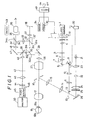
- a laser beam such as from a red-light He-Ne (wavelength: 632.8nm) type laser beam source 1 is passed through two light quantity adjustment filters 2 and 3 and a condenser lens 4, and is then formed into a parallel beam by a collimating lens 5. Following this, the beam is set to a suitable diameter by an aperture 6 and passes through a laser focusing lens 7 which is for adjusting the size of the area the beam illuminates on a fundus 18b of an eye 18 under examination. The beam is then directed via a mirror 8 and a swingable mirror 9 to pass through relay lenses 10 and 11.
- a red-light He-Ne (wavelength: 632.8nm) type laser beam source 1 is passed through two light quantity adjustment filters 2 and 3 and a condenser lens 4, and is then formed into a parallel beam by a collimating lens 5. Following this, the beam is set to a suitable diameter by an aperture 6 and passes through a laser focusing lens 7 which is for adjusting the size of the area the beam illuminates on a fund
- the laser beam issuing from the relay lens 11 is reflected by a mirror 13 provided in one portion of an annular aperture 12a formed in a ring slit 12 disposed in the eye fundus illuminating projector, so that the reflected laser beam travels along the same light path leading to the eye fundus under examination as that followed by a beam of light directed onto the eye fundus to provide illumination for photography and observation.
- the laser beam passes through relay lenses 14 and 15, and via a ring mirror 16 and objective 17 passes through a cornea 18a of an eye 18 under examination to impinge on the fundus 18b of the eye, illuminating the blood vessels to be measured.
- the swingable mirror 9 is for changing the position of the beam on the fundus, and is operated by a manipulator 20, for example.
- the swingable mirror 9 can be utilized by means of a method used in an ordinary coagulator or the like whereby the angle of the mirror is changed independently in the x and y directions, relative to the optical axis.
- the swingable mirror 9 by locating the swingable mirror 9 at a position that is a conjugate of the cornea or pupil, the position of the beam on the fundus can be changed without largely altering the position at which the beam impinges on the cornea of the eye under examination 18.
- This measurement region is also illuminated by the illuminating projector of the fundus camera, facilitating observation.
- the system for providing the illumination for observation is constituted of an observation light source 21, a condenser lens 23, a condenser lens 24, a filter 25 and a mirror 26 disposed on the same light path as a photographic light source 22. Having the path of the laser beam coincide with that of the beam of photographic and observation light is convenient, because by means of the swingable mirror 9 the laser beam can be made to impinge on the desired region of the eye fundus 18b by using the mechanisms for swinging and tilting the eye fundus camera vertically and horizontally and the eye fixation means.
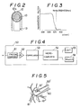
- the filter 25 disposed between the condenser lens 24 and the mirror 26 is a wavelength separation filter having the type of characteristics shown in Figure 3 to filter out red components from the observation and photographic light.
- a filter is selected that has spectral characteristics appropriate to the wavelength of the laser beam source that is employed.
- This image can be observed by a zoom-type eyepiece 36, which can be adjusted to allow operators with varying visual capabilities to focus on the reticle 35.
- the swingable mirror 32 is pivoted about a point 32a in the direction indicated by the arrow to raise it to a position 32′, whereby the observation and photographic light including speckle light from the fundus that is reflected by the swingable mirror 30 is formed into an image on photographic film 38 by the imaging lens 37.
- the system can be used for observation and photography of the fundus like an ordinary fundus camera.
- the ability to observe and photograph the fundus when it is being illuminated by the laser beam is highly convenient, as it enables the measurement point to be directly confirmed and filmed.
- the swingable mirror 30 interlocked with a measurement switch 49 is pivoted up about a point 30a to position 30′, and at the same time another swingable mirror 34 that is also interlocked with the measurement switch 49 is pivoted up about a point 34a to position 34′.
- the speckle light from the fundus reflected by the mirror 29 and observation and photographic light is formed into an image at a spatial plane point 31b that is optically equivalent to the image point 31a.
- Downstream of the point 31b is a wavelength separation mirror 39 fixed at an angle of about 45 degrees relative to the optical axis.
- the wavelength separation mirror 39 has the same kind of spectral characteristics shown in Figure 3 and therefore reflects most of the speckle light (red) produced by the He-Ne laser beam.
- the reflected speckle light passes via a Fourier-transform lens 40 and forms on a multiple detection aperture pattern 42 a diffraction-plane speckle pattern which is formed by only the light scattered from just the region of the fundus blood vessels illuminated by the laser beam.
- the multiple detection aperture pattern 42 is constituted of a plurality of small apertures and disposed at a plane of Fourier transform with respect to the eye fundus.
- the speckle light from the multiple detection aperture pattern 42 is converged by a condenser lens 43, passes through an interference filter 44 which blocks light having a wavelength other than the 632.8 nm red light produced by the He-Ne laser, and impinges on a photodetector 45 constituted of a photomultiplier for counting photons produced.
- a shutter 46 is disposed in front of the photodetector 45. The photoelectrical pulse signal produced by the photodetector 45 when the shutter 46 is open is input to an analyzer section 50.
- the observation and photography light, other than red component light, and a small amount of speckle light that is transmitted by the wavelength separation mirror 39 passes via relay lenses 47 and 48 to form an image of the fundus at the reticle 35.
- This image can be observed by means of the zoom-type eyepiece 36 described above.
- the ability to thus observe the fundus during blood flow measurement is highly effective for preventing errors such as performing measurements without noticing that the part concerned has shifted position.
- the analyzer section 50 is constituted of a photon counting unit 51, an amplifier 52, a correlator 53, a microcomputer 54, a CRT display 55 and a printer 56.
- a portion 61 ⁇ of a fundus retinal blood vessel 61 to be measured is illuminated by a laser beam 60.
- the light scattered from the illuminated portion 61 ⁇ to be measured forms a diffraction-plane speckle pattern on the multiple detection aperture pattern 42( Figure 1) which is comprised of a plurality of small apertures and disposed at the Fourier-transform plane relative to the eye fundus.
- the diffraction-plane speckle pattern 62 will be observed as a pattern in which each of the speckles 63 is distributed at random.
- Each of the speckles 63 moves according to the blood flow velocity, so that a photodetector 67 detects the speckle movement through a multiple detection aperture pattern 65 constituted of a plurality of small apertures 65′, as shown in Figure. 7b, and through a condenser lens 66.
- the velocity of the blood flow can be measured by examining this correlation time.
- the diffraction-plane speckles 63 and multiple detection aperture pattern 65 are both on the Fourier-transform plane F.
- the laser speckles reflected not only from the blood vessel 68, but also from the surrounding tissue 69 are received for detection.
- the detection is performed through an image-plane speckle pattern which is formed on a conjugate and magnified image plane.
- the detection on the image plane enables an image of the blood vessel portion 68 to be detected separately from an image of the surrounding tissue 69, thus causing no problem such as in the detection at the Fourier-transform plane.
- the illuminating laser beam 60 is focused down to a diameter that is around the same as that of the blood vessel, or smaller, and the speckle light at the Fourier-transform plane does not include any scattered light from surrounding tissue, so the speckles 63 reflect only the velocity of the blood flow in the blood vessel.
- signals containing blood flow information can be detected from the diffraction-plane speckle pattern 62 formed at the Fourier-transform plane F no matter where the detection aperture is positioned, as long as it is within the area of the speckle pattern at the Fourier-transform plane.
- Selecting the required blood vessel position from among the various blood vessels in the field of view on the fundus only requires that the laser beam be directed at the position concerned, and can be achieved by manipulating the swingable mirror 9 by means of the manipulator 20 shown in Figure 1. It is also necessary to make the beam the same size or smaller than the diameter of the target blood vessel at the measurement position. Also, as there are individual variations in the size and position of blood vessels, a means of adjusting the size of the beam is required for correct measurement. However, the mechanism becomes complex if it is made to allow a larger range of beam adjustment than necessary, and owing to such factors as aberration of the lenses, the beam becomes ellipsoidal and the intensity distribution of the beam becomes uneven.
- the size of the beam can be adjusted over a predetermined range.
- This adjustment can be carried out continuously or in steps by moving the laser focusing lens 7 along the optical axis and using a turret type arrangement for the aperture 6 by means of which the size of the aperture can be changed.
- the maximum diameter of a retina blood vessel is usually about 150 micrometers, so preferably the beam can be adjusted to a maximum diameter of 200 micrometers. If it is larger than necessary, unrequired speckle light from adjacent blood vessels or the surrounding tissue will be picked up.
- the problem here is that when the beam is moved to the desired position on the fundus, the corresponding position of the speckle pattern light 62′ on the Fourier-transform plane also moves.
- To move the detection aperture accordingly requires the same kind of involved mechanism used in the conventional apparatus.
- an arrangement is used whereby the beam can be moved anywhere within the confines of a specific angle of view range 71 (in Figure 11, the angle of view 72) that is within the observation and photographic field 70 of the fundus camera and which is also smaller than the angle of view of the observation and photographic field 70 (in Figure 11, the angle of view 73).
- laser beam movement is relatively easy when the measurement is within a range of about 3 mm in diameter in the vicinity of the center of the field of view. Therefore, for measuring at a position outside the range of movement 71, an eye fixation guide or the like may be used to locate the target position in the range 71, which is a simple, straightforward operation.
- the laser beam only has to move to the required position within the range that has been set beforehand, while observing the fundus, and that position becomes the measurement position setting, so the operation is direct and highly practical.
- apertures 65′ involved in the detection of the motion of speckles 63 in diffraction-plane speckle patterns (such as 62a, for example) formed on the Fourier-transform plane F has a plurality of detection apertures instead of the single aperture of the prior art.
- the intensity of the illuminating laser beam be reduced by however small a margin, and that operation using the laser beam is kept as short as possible.
- the light receiving optical system in the eye fundus camera has a large F-number and reflectance of a laser beam on an eye fundus is generally low and is not something that can be artificially controlled, and as such the best method is to improve the light detection sensitivity.
- the present invention has a high degree of utility, as it employs a multiple detection aperture pattern comprised of numerous small apertures used for photon correlation detection.
- the laser beam illuminates just the blood flow portion of a blood vessel to produce a speckle pattern formed only of light scattered by blood flow signal components, and this pattern is detected for photon correlation on the basis of numerous points by means of a multiple detection aperture, the surface of which is covered with small apertures.
- the detection aperture provided at the detection plane covers a wide range and wherever the position at which the speckle light arrive is moved by moving the beam, the light can always be detected at that position. This makes it easy to select the blood vessel to be measured and to perform the alignment, in addition to which, with the large increase in the amount of detected light it becomes possible to use the speckle method to measure the velocity of the blood flow in a single blood vessel.
- the method used to control the laser beam to illuminate a target blood vessel in the eye fundus may appear to be the same as the one used in the laser Doppler method, but in terms of operation and principle there are considerable differences.
- the laser beam is split into two beams which are made to intersect at a known angle at the position of the eye fundus blood vessel concerned, while another method using a single beam requires that the angle of beam incidence on the blood vessel or the angle of scattered light detection has to be known beforehand.
- speckle method according to the present invention no such difficult and time-consuming procedures are required because projection and receiving optical paths of the observation and photography light in the fundus camera can be utilized without modification.
- the laser beam is split into two beams which are directed so they intersect at the blood vessel concerned and a Doppler shift frequency corresponding to the velocity of blood cells moving through the interference fringes thus formed is measured, or in the case of a single beam, interference is produced between Doppler shift light scattered by the blood cells and light from a static scatterer provided separately that has no Doppler shift, thereby providing a heterodyne detector for measuring the Doppler shift frequency and determining the velocity of the blood flow.
- the laser speckle method utilizes time-course changes in the intensity distribution of a speckle pattern produced by the superposition of light of random phases scattering from large numbers of cells, which corresponds to blood flow velocity, the degree of said change being measured as a frequency component signal to determine the velocity of the blood flow.
- the object is speckles in translational motion, and interference arising between signals detected from the multiple apertures produces a cross-correlation component. That is, there are two types of speckle pattern motion, translational and boiling.
- Translational motion illustrated in Figure 13 refers to the translation of image plane speckles 63 in a fixed direction without any change of shape.
- Boiling illustrated in Figure 14, refers to a random, flickering motion of the image plane speckles 63, which change shape, disappear and emerge as if bubbling up to the surface.
- the present inventors noticed that the laser speckle pattern produced by light scattered by the flow of blood in the blood vessels of the eye fundus had a boiling motion.
- multiple apertures are employed for speckles with a boiling motion, as shown in Figure 15b, there is a very low probability that a given speckle 63 will cross two adjacent apertures without changing shape, the result of which is that, as shown in Figure 16b, the photon correlation function will be only the autocorrelation component 74 of each separate aperture.
- This autocorrelation component 74 is the same as that obtained in the case of detection using a single aperture, and enables the correct correlation delay time ⁇ c to be obtained.
- the apertures 65′ can be positioned relatively close together, with the result that, as shown in Figure 17a, numerous apertures 65′ can be included in the range of the speckle pattern light beam 62 to be detected, which is highly practical. Positioning the apertures 65′ too close together, however, can result in one speckle spanning two adjacent apertures 65′, as shown in Figure 17c, giving rise to cross-correlation components. Therefore, as shown in Figure 17d, the apertures 65′ should be separated by a distance that is larger than the average size of the speckles at the detection plane. As speckle size depends on optical system conditions such as magnification factor, F-number or spot size on the eye fundus, the average speckle size at the multiple detection aperture pattern should always be the standard used.
- the diameter of the apertures 65′ is set so that it provides the same signal component as when a single detection aperture is used, it is preferable to employ the type of point detection used in the conventional speckle detection method.
- an aperture may be used that has a smaller diameter than that of the average speckle concerned.
- An aperture diameter that is larger than the average speckle size would allow the presence of more than one of the speckles 63 in an aperture 65′,as shown in Figure 17e. In practice this would be undesirable, because the spatial intensity distribution would be affected by the averaging by an amount corresponding to the aperture surface, and although there would be an increase in the direct current portion, the signal portion would be decreased, producing a deterioration of the S/N ratio. This disadvantageously results in deviation of photon correlation data. Considering the above-mentioned facts, it may be preferable to make the speckle size on the speckle pattern relatively large.
- the use of the multiple detection aperture according to the invention can also be applied to image plane speckles formed at an image plane that is conjugate with the eye fundus.
- the spot size of the laser beam is very small, more particularly so small as 150 to 200 micrometers in diameter, and is substantially equal to or smaller than the diameter of the blood vessel.
- a spot image formed by the speckle light at the image plane is the same size if it is imaged in equal size, thus making the averaged size of each of the individual speckles much smaller. Accordingly, this necessitates a multiple detection aperture pattern comprised of a plurality of very small apertures (several micrometers in diameter).
- the light from the illuminated spot in the eye fundus travels as a diffraction-plane speckle light beam 62′ in the expanded parallel form and forms diffraction-plane speckles , each size of which is much greater than in the case of the image speckles.
- the correlation time derived from the photon correlation data depend to a large extent on the randomness of the fabricated pattern and the number of apertures. This will make it difficult to obtain the same signal component no matter where the speckle light falls on the multiple detection aperture pattern, which has an adverse effect on reproducibility and stability and is also undesirable in terms of production efficiency. Also, the unevenness in the intensity distribution of the speckle light beam at the detection plane accompanying the use of a random arrangement cannot be ignored.
- a characterizing feature of the present invention is the regular arrangement of the plurality of small apertures.
- a lattice arrangement may be used where in which the centers of four adjacent apertures 65′ form the four vertices of a rectangle, as shown in Figure 18a; or as shown in Figure 18b, a triangular arrangement may be used with the center of each of three adjacent apertures 65′ forming the apex points of the triangle.
- an optical fiber bundle 77′ may be used in which each optical fiber has a core diameter equal to the diameter of an aperture, arranged in a multiple detection aperture pattern at an incident plane 77, as shown in Figure 19. Such an arrangement would allow parts such as the photodetector 67 to be remotely located.
- This embodiment uses the arrangement shown in Figure 7b in which fluctuation in the intensity of the total detected speckle light coming from the apertures 65′ is detected for photon correlation as a total fluctuation by a single photodetector 67, via a condenser lens 66.
- the photoelectrical pulse signal thus obtained from the photon counting unit (PCU) 83 differs instant to instant from photoelectrical pulse signals from individual apertures.
- statistical processing can be used to obtain the same information with respect to the photon correlation, and the multiple detection aperture pattern also has the various advantages mentioned above, such as an increased amount of light.
- the statistical processing of the photoelectrical pulse signals is particularly important.
- the usual correlation processing or frequency analysis can be employed, which in practice is highly advantageous.
- the accuracy of the photon correlation processing depends greatly upon an integrated amount of light determined by the detected amount of light and detection time.
- the present invention is very useful because the detected light quantity increases, thus making the detection time ( measuring time ) shorter.
- the photon correlation function exhibits a rapid attenuation in the case of rapid blood flow as shown in Figure 20 because of rapid boiling motion of the speckles and rapid time-course fluctuation in light intensity, while exhibiting a relatively weak attenuation as indicated by a curve 78′ in the case of slow blood flow because of a slow time-course fluctuation in the light intensity.
- the reciprocal of the correlation time ⁇ c is proportional to the velocity, it becomes possible to evaluate the corresponding velocities as shown in Figure 21.
- the setting of the factor of proportionality is strongly dependent on the scattering bodies; a reliable value can be set by a prior correction based on another blood flow measurement method such as fluorescent fundus photography, or by using a correction based on a flow of blood through a glass tube that is equivalent to the blood vessel. Even if the factor of proportionality includes some deviation from the true value, the present method provides superior data reproducibility and stability, and as such is highly useful in clinical applications.
- the laser beam from the laser beam source 1 passes through the first light quantity adjustment filter 2 which can be rotated about the axis 2′ by fixed angular increments, by means of a solenoid 83 interlocked with the measurement switch 49, for example.
- filter segment 2a When the measurement switch 49 is OFF, filter segment 2a is selected which reduces the light quantity to a level that is low but enough to be perceived by the measurer.
- filter segment 2b When the measurement switch 49 is ON, filter segment 2b is selected, setting the light quantity at a level that is slightly higher than is required for the measurement.
- filter segment 2a Upon completion of the measurement, filter segment 2a is rotated back into the optical axis.
- the light quantity can be set promptly at the beginning and end of the measurement procedure.
- the filter 3 can be rotated about the axis 3′ in six steps to switch in filter segments 3a to 3f. This is done manually, and in conjunction with the filter segment 2a of filter 2 enables the light quantity required for measurement to be closely adjusted for the measurement object.
- the range of movement of the laser beam is limited to within the range 71 of the field of view. It is helpful if the measurer is able to know the said range 71 of laser beam movement on the eye fundus.
- this information is provided by using the reticle 35 (shown in Figure 1) adapted by the addition of a double circle 81 to the existing crosshairs, the double circle 81 being used to indicate the said range of laser beam movement, as shown in Figure 23a. This has the added convenience that the double circle can be used to correct the diopter.
- the view of the eye fundus should be magnified to facilitate the precise positioning of the laser beam on the blood vessel concerned. Observation will also be aided by using a wider angle of view that provides an overview of the blood vessels of the eye fundus. To achieve this, it is necessary to be able to change the angle of view to match the measurement objective.
- the light receiving system of an ordinary eye fundus camera is provided with lenses for varying the angle of view. However, this is not suitable for the present apparatus which detects the speckle pattern via the light receiving system, meaning that changing the angle of view would alter the detection conditions by changing the magnification of the image.
- the above objective is attained by providing the observation eyepiece 36 (shown in Figure 1) with a zoom capability, which enables the magnification of the observation field of view to be smoothly varied without altering the speckle detection system conditions.
- the minimum magnification can be set to the standard eye fundus camera observation viewing angle, as shown in Figure 23b, and the maximum magnification should be set in accordance with an angle of view whereby, as shown in Figure 23c, even at the highest magnification the double circle 81 of the reticle that indicates the range of laser beam movement is within the field of view 82′.
- the adjustment of the laser beam position can be observed regardless of whether the zoom-type eyepiece is at a magnified or standard setting.
- the specification of the optical axis of the speckle light detection section is particularly precise, and in measurement operations, too, a high degree of stability is required of the wavelength separation mirror. As such, a method whereby the wavelength separation mirror has to be mechanically operated each time does not meet these requirements.
- the vibration produced by the retraction of a wavelength separation mirror causes vibration of the optical path along which the speckle light is propagated and is thereby manifested at the detection plane as speckle pattern vibration, and thus ends up as speckle signal noise.
- speckle pattern vibration As a magnified image system is employed in the detection of the speckle light, the effect of such vibration is particularly pronounced.
- the retraction position of the mirror lacks sufficient reproducibility.
- the wavelength separation mirror that defines the optical axis of the speckle light detection system is movable, it cannot be adequately aligned and adjusted when the apparatus is being manufactured, and there is also variance from unit to unit.
- there is also the concern that frequent use will affect the mechanical instability as a result of age softening and deterioration in service durability.
- the wavelength separation mirror 39 is fixed in position and there are no moveable mirrors that can be moved into the optical path along which the speckle light travels.
- a swingable mirror 30 is provided before the wavelength separation mirror 39. Retracting this mirror from the optical path enables the speckle light to be directed into the optical detection system via the wavelength separation mirror 39 which has been fixed beforehand at a precisely predetermined position. Because the mirror 39 is fixed, the optical axis of the speckle light remains stable, enhancing the quality of the measurements.
- This problem is solved in this embodiment by interlocking the swingable mirror 30 with the measurement switch 49 so that when the switch 49 is switched ON the mirror 30 is retracted from the optical path, and when the switch 49 is switched OFF the mirror 30 is inserted into the optical path.
- Another swingable mirror 34 is also interlocked with the measurement switch so that when the switch is switched ON for measurement, the mirror 34 is similarly retracted from the optical path, allowing light of a wavelength component that is transmitted through the wavelength separation mirror 39 to be used for observation purposes.
- switch 49 is OFF and the mirror 34 is located in the optical path and therefore reflects light coming from the lens 33 to enable the light to be observed. It is therefore possible to observe the eye fundus during the measurement process.
- Measurement is usually started and ended as a volitional act of the measurer, the precise timing cannot be communicated either to the person undergoing examination or to others involved in the procedure, such as persons handling the signal analysis or assisting in the measurement. This is especially the case when the measurement only takes a second or less, and can therefore be finished before anyone else notices.
- the subject has to cooperate by not moving; there may be cases where signal analyst cannot decide whether an input is a true measurement signal or just noise; and there may be insufficient communication with the others assisting with the measurement.
- an electronically generated sound is used to signal that measurement is in progress.
- the signal is sound when the measurement switch is switched ON to begin the measurement and when the switch has been turned off and is then turned on to resume measurement, as well as when the measurement is carried out from start to finish without a break.
- the signal enables the precise time at which the measurement is started and stopped to be communicated to all participants, thereby solving the above problems and enhancing the utility of the apparatus.
Applications Claiming Priority (2)
| Application Number | Priority Date | Filing Date | Title |
|---|---|---|---|
| JP63091672A JPH01262835A (ja) | 1988-04-15 | 1988-04-15 | 眼科診断方法及び装置 |
| JP91672/88 | 1988-04-15 |
Publications (2)
| Publication Number | Publication Date |
|---|---|
| EP0337745A1 true EP0337745A1 (de) | 1989-10-18 |
| EP0337745B1 EP0337745B1 (de) | 1994-01-05 |
Family
ID=14032974
Family Applications (1)
| Application Number | Title | Priority Date | Filing Date |
|---|---|---|---|
| EP89303590A Expired - Lifetime EP0337745B1 (de) | 1988-04-15 | 1989-04-12 | Ophthalmoskopisches Diagnoseverfahren und Gerät |
Country Status (4)
| Country | Link |
|---|---|
| US (1) | US4952050A (de) |
| EP (1) | EP0337745B1 (de) |
| JP (1) | JPH01262835A (de) |
| DE (1) | DE68911975T2 (de) |
Cited By (2)
| Publication number | Priority date | Publication date | Assignee | Title |
|---|---|---|---|---|
| WO2003009745A3 (en) * | 2001-07-23 | 2003-09-25 | Visual Pathways Inc | Instruments and methods for examining and quantifying cataracts |
| WO2008157359A3 (en) * | 2007-06-15 | 2009-02-19 | Norbert Massie | Method and apparatus for imaging an eye of a small animal |
Families Citing this family (24)
| Publication number | Priority date | Publication date | Assignee | Title |
|---|---|---|---|---|
| EP0392742B1 (de) * | 1989-04-10 | 1995-06-28 | Kowa Company Ltd. | Verfahren und Gerät für augenoptische Messungen |
| JPH0621868B2 (ja) * | 1989-09-26 | 1994-03-23 | 新技術事業団 | ヘテロダイン検波結像系及び該結像系を用いた光断層像画像化装置 |
| JP2813899B2 (ja) * | 1989-09-26 | 1998-10-22 | 仁 藤居 | 眼科測定装置 |
| US5016643A (en) * | 1990-05-02 | 1991-05-21 | Board Of Regents, The University Of Texas System | Vascular entoptoscope |
| JP3363530B2 (ja) * | 1993-06-28 | 2003-01-08 | キヤノン株式会社 | 眼底血流計 |
| JP3332535B2 (ja) * | 1993-12-14 | 2002-10-07 | キヤノン株式会社 | 眼科測定装置 |
| US5935942A (en) * | 1994-12-14 | 1999-08-10 | Zeimer; Ran | Selective and non-invasive visualization or treatment of vasculature |
| JPH08215150A (ja) * | 1995-02-09 | 1996-08-27 | Canon Inc | 眼科診断装置 |
| US6569104B2 (en) * | 1998-07-16 | 2003-05-27 | Canon Kabushiki Kaisha | Blood vessel detecting apparatus |
| US7055955B2 (en) * | 2001-02-27 | 2006-06-06 | Canon Kabushiki Kaisha | Eye fundus examination apparatus |
| US7113817B1 (en) * | 2001-10-04 | 2006-09-26 | Wintec, Llc | Optical imaging of blood circulation velocities |
| US7092150B1 (en) * | 2003-12-11 | 2006-08-15 | Computer Optics, Inc | Optically compensated infrared zoom lens having a single movable lens carriage and no aspheric lenses |
| US7252661B2 (en) * | 2003-12-23 | 2007-08-07 | Alcon Refractivehorizons, Inc. | Method and system for patient optical fixation |
| US7766903B2 (en) * | 2003-12-24 | 2010-08-03 | The Board Of Trustees Of The Leland Stanford Junior University | Patterned laser treatment of the retina |
| US7452080B2 (en) * | 2004-06-10 | 2008-11-18 | Optimedica Corporation | Scanning ophthalmic fixation method and apparatus |
| JP4755430B2 (ja) * | 2005-03-10 | 2011-08-24 | 興和株式会社 | 眼底蛍光測定装置 |
| US7593559B2 (en) * | 2005-11-18 | 2009-09-22 | Duke University | Method and system of coregistrating optical coherence tomography (OCT) with other clinical tests |
| US9889043B2 (en) * | 2006-01-20 | 2018-02-13 | Lensar, Inc. | System and apparatus for delivering a laser beam to the lens of an eye |
| DE102008049881A1 (de) * | 2008-09-30 | 2010-04-01 | Carl Zeiss Meditec Ag | Anordnung und Verfahren zur Messung einer Augenbewegung, insbesondere einer Bewegung des Augenhintergrunds |
| DE102008049846A1 (de) * | 2008-09-30 | 2010-04-01 | Carl Zeiss Meditec Ag | Anordnung und Verfahren zur schnellen Messung einer Augenbewegung |
| US8596786B2 (en) | 2008-09-30 | 2013-12-03 | Carl Zeiss Meditec Ag | Arrangements and method for measuring an eye movement, particularly a movement of the fundus of the eye |
| US8275450B2 (en) * | 2009-08-05 | 2012-09-25 | Wintec Llc | Multiple images, multiple exposure times, optical imaging of blood circulation velocities |
| DE102013112553A1 (de) * | 2013-11-14 | 2015-06-03 | Odos Imaging Ltd. | Beleuchtungsvorrichtung und Verfahren zum Beleuchten eines Objekts |
| CN105380638B (zh) * | 2015-12-15 | 2019-02-26 | 黄恺 | 一种用于激光散斑血流速度的定量成像装置及其方法 |
Citations (2)
| Publication number | Priority date | Publication date | Assignee | Title |
|---|---|---|---|---|
| EP0234869A2 (de) * | 1986-02-25 | 1987-09-02 | Kowa Company, Ltd. | Verfahren und Gerät für Augendiagnostik |
| EP0285314A1 (de) * | 1987-03-31 | 1988-10-05 | Kowa Company, Ltd. | Gerät zur Diagnostik in der Augenheilkunde |
Family Cites Families (3)
| Publication number | Priority date | Publication date | Assignee | Title |
|---|---|---|---|---|
| US4423931A (en) * | 1980-09-09 | 1984-01-03 | Shapiro Jerrold M | Fundus camera accessory for analysis of the ocular fundus contour |
| US4402601A (en) * | 1980-12-31 | 1983-09-06 | Riva Charles E | Fundus camera-based retinal laser doppler velocimeter |
| US4950070A (en) * | 1988-04-08 | 1990-08-21 | Kowa Company Ltd. | Ophthalmological diagnosis method and apparatus |
-
1988
- 1988-04-15 JP JP63091672A patent/JPH01262835A/ja active Pending
-
1989
- 1989-04-12 EP EP89303590A patent/EP0337745B1/de not_active Expired - Lifetime
- 1989-04-12 DE DE68911975T patent/DE68911975T2/de not_active Expired - Fee Related
- 1989-04-13 US US07/337,393 patent/US4952050A/en not_active Expired - Fee Related
Patent Citations (2)
| Publication number | Priority date | Publication date | Assignee | Title |
|---|---|---|---|---|
| EP0234869A2 (de) * | 1986-02-25 | 1987-09-02 | Kowa Company, Ltd. | Verfahren und Gerät für Augendiagnostik |
| EP0285314A1 (de) * | 1987-03-31 | 1988-10-05 | Kowa Company, Ltd. | Gerät zur Diagnostik in der Augenheilkunde |
Non-Patent Citations (2)
| Title |
|---|
| OPTICS AND LASER TECHNOLOGY * |
| OPTICS LETTERS * |
Cited By (5)
| Publication number | Priority date | Publication date | Assignee | Title |
|---|---|---|---|---|
| WO2003009745A3 (en) * | 2001-07-23 | 2003-09-25 | Visual Pathways Inc | Instruments and methods for examining and quantifying cataracts |
| US6834958B2 (en) | 2001-07-23 | 2004-12-28 | Visual Pathways, Inc. | Instruments and methods for examining and quantifying cataracts |
| US7156518B2 (en) | 2001-07-23 | 2007-01-02 | Visual Pathways, Inc. | Cataract imaging apparatus |
| WO2008157359A3 (en) * | 2007-06-15 | 2009-02-19 | Norbert Massie | Method and apparatus for imaging an eye of a small animal |
| US7993000B2 (en) | 2007-06-15 | 2011-08-09 | Phoenix Research Laboratories | Method and apparatus for imaging an eye of a small animal |
Also Published As
| Publication number | Publication date |
|---|---|
| US4952050A (en) | 1990-08-28 |
| DE68911975T2 (de) | 1994-05-19 |
| EP0337745B1 (de) | 1994-01-05 |
| DE68911975D1 (de) | 1994-02-17 |
| JPH01262835A (ja) | 1989-10-19 |
Similar Documents
| Publication | Publication Date | Title |
|---|---|---|
| US4952050A (en) | Ophthalmological diagnosis method and apparatus | |
| EP0392744B1 (de) | Ophthalmologisches Messverfahren und Einrichtung | |
| US5058596A (en) | Ophthalmological measurement method and apparatus | |
| EP0285314B1 (de) | Gerät zur Diagnostik in der Augenheilkunde | |
| US6192269B1 (en) | Ophthalmological measurement apparatus | |
| JPH1075931A (ja) | 眼底検査装置 | |
| EP0392742B1 (de) | Verfahren und Gerät für augenoptische Messungen | |
| US4950070A (en) | Ophthalmological diagnosis method and apparatus | |
| EP0386927A1 (de) | Gerät zur Diagnostik in der Augenheilkunde | |
| US6607272B1 (en) | Retinal blood flow measuring apparatus using a laser beam | |
| US6302850B1 (en) | Fundus blood flow metering method | |
| JPH01256924A (ja) | 眼科診断方法及び装置 | |
| JP3762025B2 (ja) | 眼科検査装置 | |
| US6685650B2 (en) | Fundus blood flowmeter | |
| JP3591952B2 (ja) | 眼底検査装置 | |
| JP3636533B2 (ja) | 眼科診断装置 | |
| JP3762035B2 (ja) | 眼科機器 | |
| JP3639658B2 (ja) | 眼科検査用光束偏向装置 | |
| JP3636553B2 (ja) | 眼底検査装置 | |
| JPH01256926A (ja) | 眼科診断方法及び装置 | |
| JP3780058B2 (ja) | 眼科装置 | |
| JPH01256922A (ja) | 眼科診断装置 | |
| JP3535601B2 (ja) | 眼科診断装置 | |
| JPH01256925A (ja) | 眼科診断装置 | |
| JPH02274220A (ja) | 眼科診断装置 |
Legal Events
| Date | Code | Title | Description |
|---|---|---|---|
| PUAI | Public reference made under article 153(3) epc to a published international application that has entered the european phase |
Free format text: ORIGINAL CODE: 0009012 |
|
| AK | Designated contracting states |
Kind code of ref document: A1 Designated state(s): CH DE FR GB IT LI |
|
| 17P | Request for examination filed |
Effective date: 19900321 |
|
| 17Q | First examination report despatched |
Effective date: 19920716 |
|
| GRAA | (expected) grant |
Free format text: ORIGINAL CODE: 0009210 |
|
| AK | Designated contracting states |
Kind code of ref document: B1 Designated state(s): CH DE FR GB IT LI |
|
| ITF | It: translation for a ep patent filed |
Owner name: JACOBACCI CASETTA & PERANI S.P.A. |
|
| REF | Corresponds to: |
Ref document number: 68911975 Country of ref document: DE Date of ref document: 19940217 |
|
| PGFP | Annual fee paid to national office [announced via postgrant information from national office to epo] |
Ref country code: GB Payment date: 19940421 Year of fee payment: 6 |
|
| PGFP | Annual fee paid to national office [announced via postgrant information from national office to epo] |
Ref country code: CH Payment date: 19940426 Year of fee payment: 6 |
|
| PGFP | Annual fee paid to national office [announced via postgrant information from national office to epo] |
Ref country code: FR Payment date: 19940429 Year of fee payment: 6 |
|
| PGFP | Annual fee paid to national office [announced via postgrant information from national office to epo] |
Ref country code: DE Payment date: 19940510 Year of fee payment: 6 |
|
| EN | Fr: translation not filed | ||
| ET | Fr: translation filed | ||
| REG | Reference to a national code |
Ref country code: FR Ref legal event code: R1 |
|
| REG | Reference to a national code |
Ref country code: FR Ref legal event code: DS |
|
| PLBE | No opposition filed within time limit |
Free format text: ORIGINAL CODE: 0009261 |
|
| STAA | Information on the status of an ep patent application or granted ep patent |
Free format text: STATUS: NO OPPOSITION FILED WITHIN TIME LIMIT |
|
| 26N | No opposition filed | ||
| PG25 | Lapsed in a contracting state [announced via postgrant information from national office to epo] |
Ref country code: GB Effective date: 19950412 |
|
| PG25 | Lapsed in a contracting state [announced via postgrant information from national office to epo] |
Ref country code: LI Effective date: 19950430 Ref country code: CH Effective date: 19950430 |
|
| GBPC | Gb: european patent ceased through non-payment of renewal fee |
Effective date: 19950412 |
|
| REG | Reference to a national code |
Ref country code: CH Ref legal event code: PL |
|
| PG25 | Lapsed in a contracting state [announced via postgrant information from national office to epo] |
Ref country code: FR Effective date: 19951229 |
|
| PG25 | Lapsed in a contracting state [announced via postgrant information from national office to epo] |
Ref country code: DE Effective date: 19960103 |
|
| REG | Reference to a national code |
Ref country code: FR Ref legal event code: ST |
|
| PG25 | Lapsed in a contracting state [announced via postgrant information from national office to epo] |
Ref country code: IT Free format text: LAPSE BECAUSE OF NON-PAYMENT OF DUE FEES;WARNING: LAPSES OF ITALIAN PATENTS WITH EFFECTIVE DATE BEFORE 2007 MAY HAVE OCCURRED AT ANY TIME BEFORE 2007. THE CORRECT EFFECTIVE DATE MAY BE DIFFERENT FROM THE ONE RECORDED. Effective date: 20050412 |