EP0337717A2 - Appareil d'entraînement - Google Patents
Appareil d'entraînement Download PDFInfo
- Publication number
- EP0337717A2 EP0337717A2 EP89303545A EP89303545A EP0337717A2 EP 0337717 A2 EP0337717 A2 EP 0337717A2 EP 89303545 A EP89303545 A EP 89303545A EP 89303545 A EP89303545 A EP 89303545A EP 0337717 A2 EP0337717 A2 EP 0337717A2
- Authority
- EP
- European Patent Office
- Prior art keywords
- signal
- car
- simulated
- responsive
- providing
- Prior art date
- Legal status (The legal status is an assumption and is not a legal conclusion. Google has not performed a legal analysis and makes no representation as to the accuracy of the status listed.)
- Granted
Links
Images


Classifications
-
- G—PHYSICS
- G09—EDUCATION; CRYPTOGRAPHY; DISPLAY; ADVERTISING; SEALS
- G09B—EDUCATIONAL OR DEMONSTRATION APPLIANCES; APPLIANCES FOR TEACHING, OR COMMUNICATING WITH, THE BLIND, DEAF OR MUTE; MODELS; PLANETARIA; GLOBES; MAPS; DIAGRAMS
- G09B9/00—Simulators for teaching or training purposes
-
- G—PHYSICS
- G09—EDUCATION; CRYPTOGRAPHY; DISPLAY; ADVERTISING; SEALS
- G09B—EDUCATIONAL OR DEMONSTRATION APPLIANCES; APPLIANCES FOR TEACHING, OR COMMUNICATING WITH, THE BLIND, DEAF OR MUTE; MODELS; PLANETARIA; GLOBES; MAPS; DIAGRAMS
- G09B25/00—Models for purposes not provided for in G09B23/00, e.g. full-sized devices for demonstration purposes
- G09B25/02—Models for purposes not provided for in G09B23/00, e.g. full-sized devices for demonstration purposes of industrial processes; of machinery
Definitions
- This invention relates to a training kit and, in particular, to a simulator for use by maintenance or service personnel in learning how to detect faults in electrical systems.
- a training kit comprising a portable electronic simulation of an apparatus, the simulation including manually operable means to control parameters of the simulation and a signal processor with associated software serving to lead an operator through a training or servicing program in dependence upon the values of parameters determined by the operator by means of the manually operable means.
- the kit of this invention offers a relatively inexpensive method of training machine operators, setters and service engineers.
- the method permits trainees to study at their own pace and does not require a space model of any type, but which relies upon a portable, completely electronic simulation of an apparatus.
- With electronics it is possible to provide a simulation of the function and operation of almost any apparatus, and the kit of the invention makes use of such a simulation together with a microprocessor and associated software.
- Probes can be connected to the microprocessor and used to monitor machine states and conditions to provide information as a training or servicing aid at relative low cost and with ease of use.
- Expert information or models can also be included in the software and arranged to output information to trainees to prompt or support the training process.
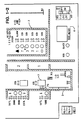
- Figs. 1 and 2 together show the front face of a portable, completely electronic simulation of a lift apparatus, the simulation comprising electronic components mounted on a surface such as a printed circuit board or boards, the simulation being of a size that enables it to be carried by a user between locations of use, for example home, work or college.
- the circuitry of the simulation accurately reproduces that of a simulated lift apparatus, and will be described in detail in connection with Figs. 4 and 5 hereinafter.
- Fig. 1 shows on the left a section 1 representing a lift shaft 2 and a car 3 therein, with winding gear 4 at the top of the shaft 2 and control buttons 5 at each of four floors between which the lift operates.
- Fig. 1 shows one of the cars 3 with its internal control buttons 6 and a set of controls 7 useable by a service engineer or the like.
- a test meter 8 having a pair of connection points for manually operable means in the form of a probe or probes 46, 48 (not shown in Fig. 1, but see Fig. 4) by which connections can be established between particular test points on the simulator and the processor within, thereby to effect required sensing or preferably simulated sensing of the operating parameters of the simulation.
- Fig. 2 shows simulated transformers and rectifiers which would be used to provide power to the control circuits of a lift.
- Relays 10 simulate typical control relays used to control the operation of a lift apparatus in response to operation of the simulated lift control buttons shown in Fig. 1. All of the voltages or resistances of these various components and relays may be simulated according to the simulated state to be described subsequently.
- the simulator of Figs. 1 and 2 is comprised of hardware, some of which is shown in Fig. 4, which includes a signal processor and various other components to be described below for leading an operator through a training and/or servicing schedule requiring the operator to respond by using the probe or probes to establish connections and sense voltages, etc., between contact or test points on the simulator, thereby to ascertain the nature of simulated faults in the lift apparatus and to effect their cure.
- the kit can include written material serving to guide and assist the operator or student in using the kit.
- the simulation can include a visual display on its front face, serving to display information relating to the operating of the simulated lift apparatus and/or information resulting from use of the probe or probes by an operator.
- FIG. 3 shows the front face of a portable, completely electronic simulation of an injection molding apparatus, the simulation again comprising electronic components carried by printed circuit boards, and showing a mimic diagram 20 of the injection molding apparatus.
- Mounted on the front face of the simulation are manually operable means in the form of knobs 21 by the use of which an operator can set control parameters which determine the quality and acceptability of the simulated final product output by the machine (described by statements provided on the liquid crystal display 22).
- the display can also provide information relating to the sequence of operation of the apparatus, or the value of parameters set by knobs 21 when adjusted by the operator. With a test probe connected to the signal processor, machine conditions, at various stages in the operating sequence, can be monitored and displayed.
- this simulator may preferably be driven by a microprocessor (not shown) with associated software which leaves an operator through a training and/or servicing schedule.
- FIG. 4 a simplified block diagram of some components which may be used in making a simulator, training or servicing kit, according to the present invention, is illustrated.
- the training kit shown in Fig. 4 would be used to form the basis of the simulator in Figs. 1 & 2 or the simulator of Fig. 3 or for any other simulator made according to the principles taught herein.
- the training kit 30 may be made of a printed circuit board having a signal processor such as a microprocessor mounted thereon but which, as mentioned, may comprise discrete components for carrying out the same functionality, a plurality of test points 34 which may be interfaced to the signal processor 32 by means of, for example but not limited to, a plurality of latches 36, a plurality of switches 38 which may similarly interface with the signal processor, again for example only, by means of latches 39 and a plurality of indicating lamps 40 which may interface with the signal processor 32 for example by means of a plurality of latches 42.
- the training kit 30 may optionally include a display 44 and/or a probe 46 or a pair of probes 46, 48 for testing and displaying the voltage or resistance across various test points 34 or similarly at test points 34 machine conditions such as temperature, pressure, speed, time, etc.
- the signal processor 32 may comprise a central processing unit (CPU) 46, a random access memory (RAM) 48, a read only memory (ROM) 50 for storing a program and various input/output (I/0) ports 52, 54, 56 all interconnected by various data, address and control lines 57.
- CPU central processing unit
- RAM random access memory
- ROM read only memory
- the simulators of Figs. 1 and 2, and also of Fig. 3, may have "test meters” which are actually really displays built-in to the training kits. These displays utilize probes in the same way as illustrated in Fig. 4, as if they were volt-ohmmeters, so as to be able to "measure” voltage or continuity across or between various test points, or machine conditions such as temperature, pressure, speed, timing, etc., these being selected/monitored by the trainee as required.
- the preferred embodiment of Fig. 4 utilizes simulated voltages and resistances between test points, depending on circumstances simulated by the program resident in ROM 50.
- one of the switches 38 is a simulated three-phase main power isolator switch which is thrown in the off position by the student so as to measure the resistance between two of the test points he has selected.
- the signal processor 32 will sense that the probes 46, 48 have been contacted with a particular two of the test points 34 and will be able to tell which test points are being interrogated by the probes through interrogation of the latches 36 in sequence.
- the signal processor Upon determining which two test points are being interrogated by the probes, the signal processor will provide the necessary signals to the display 44 in order to display the correct resistance value for the circumstance determined by the program resident in ROM 50 and explained in further detail in connection with the state machine of Fig. 5.
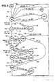
- Fig. 5 a state machine model of a lift system in which transitions from state-to-state following a typical sequence of lift operations, is shown. Because all lifts perform the same general functions, they contain similar rudimentary control and status points within their controller. Many of such points which have been illustrated in the simulation of Figs. 1 and 2 will figure in the description of the state machine of Fig. 5. Many other points which have also been illustrated will not be described to reduce the complexity of this specification. It will be understood, however, that the general principles disclosed may be extended to cover all of the desired points which may play a role in a given simulation. With respect to the points described in detail, most lifts perform an equivalent sequence of operations when performing their normal functions. The state machine described herein, in connection with Fig.
- switches 38, display 44, indicators 40 and probes 48 when implemented in the signal processor 32 of Fig. 4 to interface with the test points 34, switches 38, display 44, indicators 40 and probes 48, thus in effect simulates the entire sequence of operations that a lift performs. If one or more of the switches 38 are used to signal the signal processor 32 that a certain selected fault is to be simulated, the simulation program resident in the signal processor's ROM will cause the "lift" to fail to follow the normal sequence or fail to meet the specified criteria for transitioning between successive normal states representative of normal operation. This is indicated to the student by illuminating a lamp or displaying a signal (or by failing to do so) indicative of certain conditions within the system that is indicative of a malfunction. An inoperative condition or failure condition must then be logically determined by the student with the aid of the probes 46, 48 and the display 44.
- Each state that the simulated lift can assume is represented graphically in Fig. 5 by a circle. Mnemonics used within a circle identified the state. All transitions between states of the lift are represented graphically by arrows in between circles. Each transition is qualified by an expression whose value is either true or false. In the simulation, the lift transitions from one normal state to another in a normal controlled manner. It is assumed, for purposes of the simulation, that the expressions which qualify the transitions leading to the other states are satisfied for such normal transitions.
- An expression consists of one or more state linkages or minimum time limits used in conjunction with the operators: AND, OR, or NOT. Time is represented by the symbol T. This symbol achieves a true value only after the simulated lift has been in the state of a time value specified. It will remain true until after the state is exited.
- the signal processor will then make reference to a particular look-up table stored in ROM associated with that state which specifies the parameter values for the test points 34. These will of course change depending on the simulated state. In the real world, if such a state machine were used in a controller for controlling a real lift, any malfunction by the lift or lift controller which results in a failure to transition from a particular state in the normal sequence would be detected and instead of selecting a particular look-up table to enable the signal processor to simulate particular conditions, the state machine would indicate to a signal processor that a message should be sent to a local or central office for immediate service action. See for example U.S. Patents 4,568,909; 4,622,538; or 4,750,591.
- a simulated transition out of the normal sequence is identified by letting the signal processor select a given set of parameter values from a selected look-up table for providing the signal processor with appropriate information for indicating the proper voltage or resistance for the pair of test points 34 selected by the student with the probes 46, 48.
- a state machine might be used for example in a monitoring role where an actual failure of the lift is a causal factor for a transition out of the normal sequence.
- the causal factor for example, is generated by the signal processor itself as a simulated transition signal or may be generated, among other methods, by the throwing of a switch 38 by the student or instructor to simulate such a transition.
- test points may merely serve as points for identifying to the signal processor where the student happens to be placing the probes 46, 48. In such a case they would all be energized at the same low level DC, e.g., at 5 VDC.
- a simulator could simulate actual voltages and still remain within the scope of the present invention.
- a power-on state 100 Upon application of actual power to the simulator, a power-on state 100 will be entered after all self-test checking by the processor unit is completed. After entering the power-on state 100, the state machine will transition to a car idle state 102 as signified by a transitional line 104. It is assumed that when the simulator is powered up, the simulated lift car is running and in operation. Therefore, no abnormal states may be simulated from state 100. There is an implied entrance into the power-on state 100 any time actual power is applied or interrupted momentarily to the unit. Any time a processor reset occurs, the state machine will begin from the power-on state 100 as well.
- the car idle state 102 functionally represents a car which has no demand and is waiting at a floor.
- the signal processor 32 of Fig. 4 will select from an appropriate look-up table corresponding to the CIS state, a number of values for various parameters which must be simulated if the student utilizes the test probes to interrogate particular test points for display purposes. Assuming that actual power is applied and the technician trainee has "energized” the "lift” by switching a switch 103 "ON,” such a case implies that only voltages will be measured and all of the test points 34 can be considered by the trainee to be “energized” and therefore the signal processor will cause any of the points monitored by the probes 46, 48 to cause the display 44 to read out appropriate simulated voltages.
- the signal processor will sense that fact and "assume” that subsequent interrogations of test points are for reading resistance and the display 44 will be provided with appropriate signals for indicating simulated values of ohms.
- any of the floors illustrated in Section 1 of Fig. 1 may be selected as the initial floor for indicating the initial position of the car.
- floor 1 may be indicated by illuminating all of the LED matrix lamps in block 3, indicating that the car is idle at that floor and the doors are shut.
- the student may press a button from the group of buttons 5 illustrated in Fig. 1 or from the group 6 illustrated in Section 3 of Fig. 1, thus simulating a button input from a "passenger” either at a hall landing or within a car.
- the signal processor will detect the button (one of the buttons 38) after it is depressed and will cause an associated lamp to become illuminated, either in a "hall landing” or in the "car” illustrated on the surface of the simulator 1.
- the state machine Upon the signal processor detecting a true condition of the button input for greater than three seconds, the state machine will sequence from car idle state 102 to a car called state 106, as signified by a transitional line 108.
- an abnormal transition from the car idle state 102 can occur if the lift power goes false for greater than one second.
- the state machine will sequence from the car idle state 102 to an inoperative state 1 (INOP1) 110 as signified by a transitional line 112.
- a third transition condition out of the car idle state 102 occurs when service goes true indicating that maintenance is being performed on the lift car itself. This would be caused by, for example, the trainee pushing the "NORMAL INSP.” switch in Section 7 of the lift simulator as shown in Fig. 1. This condition will cause the state machine to sequence from the car idle state 102 to an attendant state 114 as indicated by a transitional line 116.
- each of these states 110, 114 has an associated look-up table stored in the ROM 50 from which the signal processor 32 retrieves the appropriate parameter signals, in this case voltage values which the signal processor must obtain whenever the trainee touches a pair of test points 34 so that the signal processor may display the appropriate voltages on the display 44. In this case, a voltage is appropriate for display because the "lift" is “operational.” If, after entering an inoperative state or service state, the trainee wishes to indicate that he is “deenergizing” the "lift” by switching switch 103 "OFF” for "troubleshooting" purposes, then the signal processor will display resistances instead.
- the car called state 106 functionally represents a car which has been dispatched true [BUT(T)] by either a call from a hall or car button. The car is still indicated in the idle state by the LEDs at the floor but has not been activated by a signal to cause it to "move.” Two transitions are possible from the car called state 106. A normal transition occurs when the hoistway door locks "make-up,” i.e., the hoistway door lock variable is allowed to go true [DS(T)] within a time period of 20 seconds from the entrance into the car call state.
- the hoistway or landing lock contact test points 117 are shown in Fig. 1 above each of the hoistway doors 3 in Section 2.
- the state machine Upon this occurrence, the state machine will sequence from the car called state 106 to a car ready state 118. In the event that the hoistway lock variable does not go true but remains false for a period of time greater than 20 seconds from the entrance into the car called state 106, then an abnormal transition of the state machine will occur from the car called state 106 to an inoperative 2 (INOP2) state 122, as indicated by a transitional line 124.
- INOP2 inoperative 2
- Such could be simulated by the instructor switching a fault simulating switch for signalling the processor 32 to simulate such a transition or by the student being directed to flip a certain switch prior to pushing a hall call or car call button to simulate this particular type of fault.
- an associated look-up table is consulted by the signal processor for selecting the proper voltages or resistances for displaying the parameters with the appropriate values for this particular inoperative state.
- the car ready state 118 functionally represents the condition that the car has been commanded to go, and the hoistway door locks have closed. There are two transitions possible from the car ready state. The normal transition is the occurrence of a brake lift on the lift car. Such would be indicated by a lamp 119 being extinguished as shown in Fig. 1 in Section 4, for example. This lifting of the brake must occur within 15 seconds after entering the car ready state 118. Upon the occurrence of brake lift within 15 seconds, the state machine will sequence from the car ready state 118 to a car active state 126 as indicated by a transitional line 128.
- the state machine will sequence from the car ready state 118 to an inoperative 3 (INOP3) state 130 as indicated by a transitional line 132.
- This abnormal transition from the car ready state 118 would be accompanied by the signal processor accessing ROM 50 to obtain the proper values of parameters for this particular inoperative state for displaying the proper information in response to the student touching a pair of test points 34 with the probes 46, 48.
- Also provided by the processor are various signals to the car and hoistway areas in order to display simulated car and door movement.
- the car active state 126 functionally represents the condition that the car is in motion. This may be represented in Section 2 of Fig. 1 by having the light emitting diodes (LEDs) gradually make their way one vertical line at a time, for example, upwards from landing 1 to landing 2. Thus, with all LEDs in the matrix 3 at the first landing illuminated at the outset, the bottom row of LEDs may be extinguished in the first landing box while at the same time the bottom row in the second landing box is illuminated, and so on, one row at a time, until all of the rows in landing 1 are extinguished and all of the rows in landing 2 box are illuminated.
- the car active state is the normal run mode for the lift car and is the predominant mode that a lift takes during a run.
- the safety chain is a chain of series-connected normally closed safety related contacts the opening of any one or more of which constitutes a braking of "the safety chain” and the assumption by the safety chain of a false value).
- the state machine will sequence from the car active state 126 to the car stopped state 136. Note that the state machine assumes no time limit between going from the car active state 126 to the car stopped state, since it is not known how long the actual run will take. Nor it is of any importance to the state machine in monitoring the sequence of operations.
- An abnormal transition from the car active state 126 can be simulated by switching an appropriate switch 38 indicative of a safety chain variable being abnormal along with the brake lift variable being abnormal along with the brake lift variable being false as indicated by a transitional line 138 to an inoperative 6 (INOP6) state 140.
- the transition line 138 indicates a stoppage of the lift car by the opening of the safety chain.
- the car stopped state 136 functionally represents the condition that the brake has dropped on the lift and the car is now stopped. This is simulated by the signal processor sending out a signal to one of the latches 42 to cause one of the indicator lamps 40, specifically the lamp 119 shown in Fig. 1, to become illuminated indicating that the brake has dropped. If the student wishes to "deenergize” the "lift” he may flip the switch 103 to the “OFF” position in order to "test” the "continuity" of a lift brake lift contact 141 with the probes 46, 48. ln that case, the signal processor would cause the display 44 to read out the appropriate open or closed circuit indication.
- a normal transition from the car stopped state is the assumption by the door open variable of the true value within one second of entering the car stopped state 136.
- the state machine Upon the signal processor providing the door open variable with a true value within one second of entering the car stopped state 136, the state machine will sequence from the car stopped state 136 to the car door open state 144.
- An abnormal transition from the car stopped state 136 is the detection of the door open variable remaining false for a period of greater than 5 seconds after entering the car stopped state 136.
- the condition may be provided by the signal processor in response to an appropriate switch 38 being activated by the instructor or the student at the beginning or at some point during the exercise. This will result in a transition to an inoperative 4 (INOP4) state 150 as indicated by a transitional line 152.
- the signal processor may then select an appropriate look-up table in the ROM 50 and provide appropriate displays in response to the student touching a pair of test points 34 with probes 46, 48 wherein the test points correspond to, for example, the car gate lock contacts 153 indicated in Section 3 of Fig. 1.
- the car door open state functionally represents the opening of the inner doors of the lift after the car has stopped at a floor. It represents the conclusion of a normal lift run.
- the normal transition from the car door open state occurs upon detection of the opening of the hoistway doors (the door switch variable represented by typical contacts 117 going false) which results in a transition to the car idle state 102. This represents a completed sequence of lift operation and will result in the beginning of the entire sequence again.
- the abnormal transition condition from the car door open state 144 is for the door switch to remain true for a period of greater than 20 seconds after the state machine enters the car door open state 144 as indicated by a transitional line 154 to an inoperative 5 (INOP5) state 156.
- The represents the occurrence of a locked hoistway door or a failure of the lift doors to open for some other reason.
- Such functionally represents the performance of some maintenance action upon a lift by a qualified repairman.
- the service variable achieves a true value when the service switch (NORMAL INSP. in Fig. 1 at numeral 7).
- the service variable achieves a true value when the service switch associated with the simulator is turned to an ON position.
- the detection of the occurrence of the service variable going true by the signal processor will cause a transition from the car idle state 102 to the service state 114, as previously described (the service state is also referred to in lift parlance as the "attendant" state).
- the normal transition from the attendant state is the detection of the service variable in the false condition as indicated by a transition line 158 back to the car idle state 102.
- This transition 158 represents the time when the student releases the switch indicating that he has performed his "maintenance action" on the "lift.” At that time, the state machine sequences from the attendance state 114 to the car idle state 102 and begins again to simulate the operation of a normally operating lift.
- the state machine transitions from the car idle state 102 to the inoperative 1 state 110.
- Appropriate signals and/or display information will be provided to the student from an associated look-up table in ROM 50.
- the normal transition condition from state 110 is the detection of the power variable going true as indicated by a transitional line 166.
- the state machine will sequence from state 110 back to the car idle state 102 and will resume operating the simulation of the lift come as normal as indicated by a transitional line 166.
- the inoperative 2 state 122 functionally represents a failure of a hoistway door to close. It is exited upon detection of the Hoistway Door Lock going true with a transition back to the Car Idle State 102 as indicated by a transition line 170.
- the inoperative 3 state 130 functionally represents the failure of the brake to lift for the lift car within 15 seconds of the state machine entering the car ready state and the brake lift variable at the same time being false.
- a possible transition from the inoperative 3 state 130 is to the car door open state 144 which occurs when the door open variable is detected going true after entering the inoperative 3 state 130. This produces an immediate entrance to the car door open state 144 as indicated by a transitional line 190.
- a transition out of the inoperative 3 state 130 to the car active state 126 occurs if a brake lift is detected as being true after entering state 130 as indicated by a transitional line 194.
- a button variable is false for greater than 5 seconds, as indicated by a transitional line 196, a transition is made to the car idle state 102.
- the inoperative 4 state 150 represents the condition of a door open variable going false, corresponding to a door open actuator failure. It is possible to transition from the inoperative 4 state 150 to the car door open state 144 upon detecting the door open variable going true as indicated by a transitional line 202. It is also possible to transition from the inoperative 4 state 150 to the car active state 126 upon detection of the brake lift variable going true as indicated by a transitional line 204. A transition to state 150 may indicate that the door open mechanism has "failed.”
- the inoperative 5 state 156 represents the failure of the hoistway door actuators to open. It is entered from the car door open state 144 if the hoistway doors do not "open" within 20 seconds after entering the car door open state 144. A transition from the inoperative 5 state 156 to the car idle state 102 occurs if the door switch variable goes false, as indicated by a transitional line 222.
- the inoperative 6 state 140 functionally represents the stoppage of the lift car by an opening of the safety chain. Detection of the safety variable going true will result in an immediate transition to the car stopped state 136 as indicated by a transitional line 244.
- a selected lift system will have an electrical control schematic diagram provided by the design engineers for installation and troubleshooting purposes.
- the various nodes may be defined according to various Boolean expressions which may be stored in the ROM 50.
- the various nodes may be defined according to various Boolean expressions which may be stored in the ROM 50.
- the ROM 50 When all of the simulated condition signals are taken into account, one of the equations will be satisfied for each node.
- the satisfaction of a particular equation for a particular node will point to particular storage locations also in ROM 50 for quantitatively defining in terms of voltage or resistance, for example, the value of that node with respect to any number of other nodes.
Landscapes
- Engineering & Computer Science (AREA)
- Theoretical Computer Science (AREA)
- Business, Economics & Management (AREA)
- Physics & Mathematics (AREA)
- Educational Administration (AREA)
- Educational Technology (AREA)
- General Physics & Mathematics (AREA)
- Management, Administration, Business Operations System, And Electronic Commerce (AREA)
- Elevator Control (AREA)
- Debugging And Monitoring (AREA)
- Indicating And Signalling Devices For Elevators (AREA)
- Maintenance And Inspection Apparatuses For Elevators (AREA)
Applications Claiming Priority (2)
| Application Number | Priority Date | Filing Date | Title |
|---|---|---|---|
| GB8808446 | 1988-04-11 | ||
| GB888808446A GB8808446D0 (en) | 1988-04-11 | 1988-04-11 | Training/servicing kit |
Publications (3)
| Publication Number | Publication Date |
|---|---|
| EP0337717A2 true EP0337717A2 (fr) | 1989-10-18 |
| EP0337717A3 EP0337717A3 (fr) | 1992-04-15 |
| EP0337717B1 EP0337717B1 (fr) | 1996-12-04 |
Family
ID=10634947
Family Applications (1)
| Application Number | Title | Priority Date | Filing Date |
|---|---|---|---|
| EP89303545A Expired - Lifetime EP0337717B1 (fr) | 1988-04-11 | 1989-04-11 | Appareil d'entraînement |
Country Status (12)
| Country | Link |
|---|---|
| US (1) | US4964804A (fr) |
| EP (1) | EP0337717B1 (fr) |
| JP (1) | JPH0234888A (fr) |
| AU (1) | AU611550B2 (fr) |
| BR (1) | BR8901697A (fr) |
| CA (1) | CA1325677C (fr) |
| DE (1) | DE68927506T2 (fr) |
| ES (1) | ES2097112T3 (fr) |
| FI (1) | FI891671A (fr) |
| GB (1) | GB8808446D0 (fr) |
| MX (1) | MX174211B (fr) |
| ZA (1) | ZA892601B (fr) |
Cited By (6)
| Publication number | Priority date | Publication date | Assignee | Title |
|---|---|---|---|---|
| GB2250370A (en) * | 1990-11-28 | 1992-06-03 | Otis Elevator Co | Training device for lift service personnel |
| GB2250624A (en) * | 1990-11-28 | 1992-06-10 | Otis Elevator Co | Training device for lift service personnel |
| WO1993002437A1 (fr) * | 1991-07-15 | 1993-02-04 | Hughes Aircraft Company | Systeme de traitement de demande de controle d'etat |
| WO1993008552A1 (fr) * | 1991-10-23 | 1993-04-29 | Hughes Aircraft Company | Simulateur de traitement industriel automatise |
| EP0657858A2 (fr) * | 1993-12-10 | 1995-06-14 | ECC Simulation Limited | Aide pour formation |
| CN106448317A (zh) * | 2016-08-31 | 2017-02-22 | 广州益业机电设备科技有限公司 | 汽车教学故障模拟外置电路及故障设置平台 |
Families Citing this family (10)
| Publication number | Priority date | Publication date | Assignee | Title |
|---|---|---|---|---|
| US5391081A (en) * | 1992-05-13 | 1995-02-21 | University Of Florida Research Foundation, Incorporated | Method and apparatus for simulating neuromuscular stimulation during medical surgery |
| US5721403A (en) * | 1996-03-29 | 1998-02-24 | Otis Elevator Company | Selective circuit bypass for elevator system |
| US7128578B2 (en) * | 2002-05-29 | 2006-10-31 | University Of Florida Research Foundation, Inc. | Interactive simulation of a pneumatic system |
| US20080299534A1 (en) * | 2007-05-31 | 2008-12-04 | Jesse Richardson | Training apparatus for servicing domestic appliances |
| JP5379387B2 (ja) * | 2008-02-29 | 2013-12-25 | Idec株式会社 | 安全機器教育用ツール及びその組み立てキット |
| CN103247211B (zh) * | 2013-05-23 | 2016-01-20 | 国家电网公司 | 一种电气故障快速设置装置 |
| CN105856488B (zh) * | 2016-06-08 | 2018-01-05 | 淮安信息职业技术学院 | 一种注塑教学一体机 |
| CN108777091A (zh) * | 2018-06-29 | 2018-11-09 | 武汉天之逸科技有限公司 | 电梯轿厢智能教学实训控制系统 |
| CN109969893A (zh) * | 2019-04-09 | 2019-07-05 | 普林志教育科技(厦门)有限公司 | 电梯实训平台 |
| CN113554916B (zh) * | 2021-07-27 | 2023-02-10 | 广东电网有限责任公司 | 一种低压集抄运维仿真系统 |
Citations (10)
| Publication number | Priority date | Publication date | Assignee | Title |
|---|---|---|---|---|
| GB2025663A (en) * | 1978-07-07 | 1980-01-23 | Hitachi Ltd | Elevator test operation apparatus |
| US4370717A (en) * | 1974-09-30 | 1983-01-25 | Westinghouse Electric Corp. | Elevator bank simulation system |
| US4425097A (en) * | 1981-09-08 | 1984-01-10 | Owens Lawrence L | Apparatus for training equipment operators |
| GB2136158A (en) * | 1983-02-22 | 1984-09-12 | Otis Elevator Co | Servicing a software-controlled lift |
| FR2553915A1 (fr) * | 1983-10-19 | 1985-04-26 | Paris 1 Universite | Dispositif pedagogique programmable simulant le fonctionnement d'un ascenseur |
| EP0146412A2 (fr) * | 1983-12-19 | 1985-06-26 | Otis Elevator Company | Système de surveillance à distance de l'état d'un appareil |
| US4568909A (en) * | 1983-12-19 | 1986-02-04 | United Technologies Corporation | Remote elevator monitoring system |
| GB2178875A (en) * | 1985-08-10 | 1987-02-18 | Ferranti Plc | Plant maintenance training |
| US4697243A (en) * | 1985-07-25 | 1987-09-29 | Westinghouse Electric Corp. | Methods of servicing an elevator system |
| US4750591A (en) * | 1987-07-10 | 1988-06-14 | Otis Elevator Company | Elevator car door and motion sequence monitoring apparatus and method |
Family Cites Families (8)
| Publication number | Priority date | Publication date | Assignee | Title |
|---|---|---|---|---|
| US3832790A (en) * | 1972-09-29 | 1974-09-03 | Edp Ecc Corp | Programmable trainer |
| GB1542910A (en) * | 1976-09-27 | 1979-03-28 | Grumman Aerospace Corp | Sequence training apparatus |
| US4167821A (en) * | 1977-03-02 | 1979-09-18 | Educational Computer Corp. | Programmable simulated trainer |
| US4316720A (en) * | 1979-03-26 | 1982-02-23 | The Singer Company | Maintenance training device |
| US4518361A (en) * | 1982-08-05 | 1985-05-21 | Conway Malcolm J | Method and apparatus for effecting and evaluating action upon visual imaging |
| US4613952A (en) * | 1983-07-11 | 1986-09-23 | Foster Wheeler Energy Corporation | Simulator for an industrial plant |
| US4623312A (en) * | 1984-10-31 | 1986-11-18 | Training Labs, Inc. | Changeable modular training system to provide instruction for installing, servicing, troubleshooting and operating electromechanical control systems |
| US4776798A (en) * | 1985-12-06 | 1988-10-11 | Training Labs Inc. | Energy managment microprocessing training system providing instruction for the programming and computerization of mechanical and electrical control systems, adapted to be a component with and an improvement for existing changeable modular training systems |
-
1988
- 1988-04-11 GB GB888808446A patent/GB8808446D0/en active Pending
-
1989
- 1989-04-07 AU AU32594/89A patent/AU611550B2/en not_active Ceased
- 1989-04-07 FI FI891671A patent/FI891671A/fi not_active IP Right Cessation
- 1989-04-10 ZA ZA892601A patent/ZA892601B/xx unknown
- 1989-04-10 BR BR898901697A patent/BR8901697A/pt not_active Application Discontinuation
- 1989-04-11 MX MX1561089A patent/MX174211B/es unknown
- 1989-04-11 DE DE68927506T patent/DE68927506T2/de not_active Expired - Fee Related
- 1989-04-11 CA CA000596278A patent/CA1325677C/fr not_active Expired - Fee Related
- 1989-04-11 EP EP89303545A patent/EP0337717B1/fr not_active Expired - Lifetime
- 1989-04-11 ES ES89303545T patent/ES2097112T3/es not_active Expired - Lifetime
- 1989-04-11 JP JP1091680A patent/JPH0234888A/ja active Pending
- 1989-04-12 US US07/337,010 patent/US4964804A/en not_active Expired - Fee Related
Patent Citations (11)
| Publication number | Priority date | Publication date | Assignee | Title |
|---|---|---|---|---|
| US4370717A (en) * | 1974-09-30 | 1983-01-25 | Westinghouse Electric Corp. | Elevator bank simulation system |
| GB2025663A (en) * | 1978-07-07 | 1980-01-23 | Hitachi Ltd | Elevator test operation apparatus |
| US4425097A (en) * | 1981-09-08 | 1984-01-10 | Owens Lawrence L | Apparatus for training equipment operators |
| GB2136158A (en) * | 1983-02-22 | 1984-09-12 | Otis Elevator Co | Servicing a software-controlled lift |
| FR2553915A1 (fr) * | 1983-10-19 | 1985-04-26 | Paris 1 Universite | Dispositif pedagogique programmable simulant le fonctionnement d'un ascenseur |
| EP0146412A2 (fr) * | 1983-12-19 | 1985-06-26 | Otis Elevator Company | Système de surveillance à distance de l'état d'un appareil |
| US4568909A (en) * | 1983-12-19 | 1986-02-04 | United Technologies Corporation | Remote elevator monitoring system |
| US4697243A (en) * | 1985-07-25 | 1987-09-29 | Westinghouse Electric Corp. | Methods of servicing an elevator system |
| GB2178875A (en) * | 1985-08-10 | 1987-02-18 | Ferranti Plc | Plant maintenance training |
| US4750591A (en) * | 1987-07-10 | 1988-06-14 | Otis Elevator Company | Elevator car door and motion sequence monitoring apparatus and method |
| EP0298784A2 (fr) * | 1987-07-10 | 1989-01-11 | Otis Elevator Company | Appareil et méthode de surveillance du mouvement de la porte et du déplacement d'un ascenseur |
Cited By (9)
| Publication number | Priority date | Publication date | Assignee | Title |
|---|---|---|---|---|
| GB2250370A (en) * | 1990-11-28 | 1992-06-03 | Otis Elevator Co | Training device for lift service personnel |
| GB2250624A (en) * | 1990-11-28 | 1992-06-10 | Otis Elevator Co | Training device for lift service personnel |
| GB2250370B (en) * | 1990-11-28 | 1994-05-25 | Otis Elevator Co | Lift simulator |
| GB2250624B (en) * | 1990-11-28 | 1995-01-11 | Otis Elevator Co | Training device |
| WO1993002437A1 (fr) * | 1991-07-15 | 1993-02-04 | Hughes Aircraft Company | Systeme de traitement de demande de controle d'etat |
| WO1993008552A1 (fr) * | 1991-10-23 | 1993-04-29 | Hughes Aircraft Company | Simulateur de traitement industriel automatise |
| EP0657858A2 (fr) * | 1993-12-10 | 1995-06-14 | ECC Simulation Limited | Aide pour formation |
| EP0657858A3 (fr) * | 1993-12-10 | 1996-12-11 | Ecc Simulation Ltd | Aide pour formation. |
| CN106448317A (zh) * | 2016-08-31 | 2017-02-22 | 广州益业机电设备科技有限公司 | 汽车教学故障模拟外置电路及故障设置平台 |
Also Published As
| Publication number | Publication date |
|---|---|
| FI891671A (fi) | 1989-10-12 |
| ZA892601B (en) | 1990-08-29 |
| MX174211B (es) | 1994-04-28 |
| JPH0234888A (ja) | 1990-02-05 |
| DE68927506T2 (de) | 1997-04-03 |
| CA1325677C (fr) | 1993-12-28 |
| EP0337717A3 (fr) | 1992-04-15 |
| AU611550B2 (en) | 1991-06-13 |
| BR8901697A (pt) | 1989-11-21 |
| DE68927506D1 (de) | 1997-01-16 |
| US4964804A (en) | 1990-10-23 |
| FI891671A0 (fi) | 1989-04-07 |
| GB8808446D0 (en) | 1988-05-11 |
| AU3259489A (en) | 1989-10-12 |
| EP0337717B1 (fr) | 1996-12-04 |
| ES2097112T3 (es) | 1997-04-01 |
Similar Documents
| Publication | Publication Date | Title |
|---|---|---|
| EP0337717B1 (fr) | Appareil d'entraînement | |
| US4316720A (en) | Maintenance training device | |
| WO2006002527A1 (fr) | Procede et systeme de diagnostic de panne par simulation et verification de panne dans des systemes complexes commandes par un operateur | |
| JPS59172372A (ja) | ソフトウエア制御式エレベ−タ保守装置 | |
| CN105139740A (zh) | 一种电梯半实物仿真训练装置 | |
| JPS6327267B2 (fr) | ||
| CN203013117U (zh) | 教学仿真电梯电气装调考评实训系统 | |
| JPS623077B2 (fr) | ||
| JP2502766B2 (ja) | エレベ―タの故障診断装置 | |
| CN114691462A (zh) | 一种城市轨道交通车辆模拟方法及装置 | |
| JPH04268592A (ja) | リフトシミュレータ | |
| CN207249477U (zh) | 汽车天窗总成自动化测试装置 | |
| SU1132302A1 (ru) | Тренажер оператора автоматизированных систем управлени | |
| JPS5942884B2 (ja) | シ−ケンス制御プログラムのデバツギング装置 | |
| CN205317873U (zh) | 一种应用于纯电动整车控制器高温老化试验装置 | |
| GB2250624A (en) | Training device for lift service personnel | |
| CN114694443B (zh) | 一种装备维修训练平台 | |
| CN107491063A (zh) | 汽车天窗总成自动化测试装置 | |
| RU2793839C1 (ru) | Процедурный тренажер для обучения машиниста работе с тормозной системой подвижного состава | |
| CN115686971A (zh) | 一种多余度安全计算机的自动化测试装置 | |
| CN207263887U (zh) | 一种pcba模块测试治具 | |
| Sigari et al. | Portable and affordable operator training simulators | |
| KR960002448B1 (ko) | 엘리베이터의 그룹 제어장치 | |
| CN115639765A (zh) | 一种燃气轮机传感器故障模拟装置、方法及监控系统 | |
| Browne et al. | Innovative approach for dual control of electromechanical plant |
Legal Events
| Date | Code | Title | Description |
|---|---|---|---|
| PUAI | Public reference made under article 153(3) epc to a published international application that has entered the european phase |
Free format text: ORIGINAL CODE: 0009012 |
|
| AK | Designated contracting states |
Kind code of ref document: A2 Designated state(s): CH DE ES FR GB IT LI NL |
|
| 17P | Request for examination filed |
Effective date: 19900316 |
|
| PUAL | Search report despatched |
Free format text: ORIGINAL CODE: 0009013 |
|
| AK | Designated contracting states |
Kind code of ref document: A3 Designated state(s): CH DE ES FR GB IT LI NL |
|
| 17Q | First examination report despatched |
Effective date: 19950120 |
|
| GRAG | Despatch of communication of intention to grant |
Free format text: ORIGINAL CODE: EPIDOS AGRA |
|
| GRAH | Despatch of communication of intention to grant a patent |
Free format text: ORIGINAL CODE: EPIDOS IGRA |
|
| GRAH | Despatch of communication of intention to grant a patent |
Free format text: ORIGINAL CODE: EPIDOS IGRA |
|
| GRAA | (expected) grant |
Free format text: ORIGINAL CODE: 0009210 |
|
| ITF | It: translation for a ep patent filed |
Owner name: BARZANO' E ZANARDO ROMA S.P.A. |
|
| AK | Designated contracting states |
Kind code of ref document: B1 Designated state(s): CH DE ES FR GB IT LI NL |
|
| REG | Reference to a national code |
Ref country code: CH Ref legal event code: NV Representative=s name: E. BLUM & CO. PATENTANWAELTE |
|
| ET | Fr: translation filed | ||
| REF | Corresponds to: |
Ref document number: 68927506 Country of ref document: DE Date of ref document: 19970116 |
|
| PGFP | Annual fee paid to national office [announced via postgrant information from national office to epo] |
Ref country code: FR Payment date: 19970307 Year of fee payment: 9 |
|
| PGFP | Annual fee paid to national office [announced via postgrant information from national office to epo] |
Ref country code: GB Payment date: 19970319 Year of fee payment: 9 |
|
| PGFP | Annual fee paid to national office [announced via postgrant information from national office to epo] |
Ref country code: DE Payment date: 19970321 Year of fee payment: 9 |
|
| PGFP | Annual fee paid to national office [announced via postgrant information from national office to epo] |
Ref country code: CH Payment date: 19970324 Year of fee payment: 9 |
|
| PGFP | Annual fee paid to national office [announced via postgrant information from national office to epo] |
Ref country code: NL Payment date: 19970327 Year of fee payment: 9 |
|
| REG | Reference to a national code |
Ref country code: ES Ref legal event code: FG2A Ref document number: 2097112 Country of ref document: ES Kind code of ref document: T3 |
|
| PGFP | Annual fee paid to national office [announced via postgrant information from national office to epo] |
Ref country code: ES Payment date: 19970417 Year of fee payment: 9 |
|
| PLBE | No opposition filed within time limit |
Free format text: ORIGINAL CODE: 0009261 |
|
| STAA | Information on the status of an ep patent application or granted ep patent |
Free format text: STATUS: NO OPPOSITION FILED WITHIN TIME LIMIT |
|
| 26N | No opposition filed | ||
| PG25 | Lapsed in a contracting state [announced via postgrant information from national office to epo] |
Ref country code: GB Free format text: LAPSE BECAUSE OF NON-PAYMENT OF DUE FEES Effective date: 19980411 |
|
| PG25 | Lapsed in a contracting state [announced via postgrant information from national office to epo] |
Ref country code: ES Free format text: LAPSE BECAUSE OF NON-PAYMENT OF DUE FEES Effective date: 19980413 |
|
| PG25 | Lapsed in a contracting state [announced via postgrant information from national office to epo] |
Ref country code: LI Free format text: LAPSE BECAUSE OF NON-PAYMENT OF DUE FEES Effective date: 19980430 Ref country code: FR Free format text: THE PATENT HAS BEEN ANNULLED BY A DECISION OF A NATIONAL AUTHORITY Effective date: 19980430 Ref country code: CH Free format text: LAPSE BECAUSE OF NON-PAYMENT OF DUE FEES Effective date: 19980430 |
|
| PG25 | Lapsed in a contracting state [announced via postgrant information from national office to epo] |
Ref country code: NL Free format text: LAPSE BECAUSE OF NON-PAYMENT OF DUE FEES Effective date: 19981101 |
|
| GBPC | Gb: european patent ceased through non-payment of renewal fee |
Effective date: 19980411 |
|
| REG | Reference to a national code |
Ref country code: CH Ref legal event code: PL |
|
| NLV4 | Nl: lapsed or anulled due to non-payment of the annual fee |
Effective date: 19981101 |
|
| PG25 | Lapsed in a contracting state [announced via postgrant information from national office to epo] |
Ref country code: DE Free format text: LAPSE BECAUSE OF NON-PAYMENT OF DUE FEES Effective date: 19990202 |
|
| REG | Reference to a national code |
Ref country code: FR Ref legal event code: ST |
|
| REG | Reference to a national code |
Ref country code: ES Ref legal event code: FD2A Effective date: 20000503 |
|
| PG25 | Lapsed in a contracting state [announced via postgrant information from national office to epo] |
Ref country code: IT Free format text: LAPSE BECAUSE OF NON-PAYMENT OF DUE FEES Effective date: 20050411 |