EP0337437B1 - Intermodales Sattelaufliegertransportsystem auf zwei Schienenfahrzeugen - Google Patents
Intermodales Sattelaufliegertransportsystem auf zwei Schienenfahrzeugen Download PDFInfo
- Publication number
- EP0337437B1 EP0337437B1 EP89106539A EP89106539A EP0337437B1 EP 0337437 B1 EP0337437 B1 EP 0337437B1 EP 89106539 A EP89106539 A EP 89106539A EP 89106539 A EP89106539 A EP 89106539A EP 0337437 B1 EP0337437 B1 EP 0337437B1
- Authority
- EP
- European Patent Office
- Prior art keywords
- trailer
- semi
- chock
- platform
- wheels
- Prior art date
- Legal status (The legal status is an assumption and is not a legal conclusion. Google has not performed a legal analysis and makes no representation as to the accuracy of the status listed.)
- Expired - Lifetime
Links
Images


Classifications
-
- B—PERFORMING OPERATIONS; TRANSPORTING
- B60—VEHICLES IN GENERAL
- B60F—VEHICLES FOR USE BOTH ON RAIL AND ON ROAD; VEHICLES CAPABLE OF TRAVELLING IN OR ON DIFFERENT MEDIA, e.g. AMPHIBIOUS VEHICLES
- B60F1/00—Vehicles for use both on rail and on road; Conversions therefor
- B60F1/04—Vehicles for use both on rail and on road; Conversions therefor with rail and road wheels on different axles
- B60F1/046—Semi-trailer or trailer type vehicles without own propelling units
Definitions
- the present invention generally relates to railway rolling stock and, more particularly, to a system for transporting highway semi-trailers, and the like, by rail.
- the inability of railroads to effectively compete in a shorter distance market stems from two factors.
- the first factor involves the problem of matching the lengths of the semi-trailers to the flat cars.
- flat cars are available in lengths ranging from 12,19 m to 27.43 m and more, a fairly significant number are in the 24.38 to 27.43 m range.
- Semi-trailers are also available in a variety of lengths, but a significant number are in the 12.19 to 15.24 m range. Thus, it is fairly common that semi-trailers must be transported one on one because they are too long for double, tandem loading on available flat rolling stock.
- the second problem concerns the prohibitive capital costs and operating expenses associated with the loading of trailers on today's railroad flat cars. Because of terminal costs associated with loading and unloading the trailers on flat cars, railroads find it difficult to absorb such terminal costs while remaining competitive with road freight services.
- Such system uses improved rail bogies as the sole support of adjacent rear and front ends of the trailer and as the sole connecting means between such trailers, to form trains.
- the patented system includes a rail bogie having a frame structure supported on wheeled axles positioned at the respective ends of the frame structure.
- the frame structure defines a pair of end deck surfaces positioned above the wheeled axles and a central drop deck surface disposed between and below the end deck surfaces.
- a fifth wheel assembly is supported above each of the end deck surfaces for receipt of a kingpin of a semi-trailer.
- a deck plate member is pivotally secured to the drop deck surface for planar rotation with respect thereto about a substantially vertical axis.
- a pair of transversely spaced, longitudinally extending, internal and external rub rail members extend upwardly from the drop deck plate member for receipt of semi-trailer tandems therebetween.
- the drop deck plate is movable between first and second positions. In one position, the rub rail members on the deck plate are substantially parallel to the longitudinal axis of the frame structure. When in its second position, the rub rail members on the deck plate member are substantially perpendicular to the longitudinal axis of the frame structure.
- a semi-trailer extends between a pair of adjacent bogies.
- the tandems of the trailer are received and supported on the drop deck plate between the corresponding rub rail members of a first bogie and the kingpin of the trailer is received and supported on the fifth wheel assembly of the immediately adjacent bogie.
- the procedure for loading and unloading the semi-trailers onto and from the bogies is facilitated by the rotating drop deck plate.
- This system is limited in its ability to secure a semi-trailer against endwise displacement relative to the deck plate member. Separate devices need to be provided to secure the semi-trailer tandems relative to the deck plate. Should such securement devices become dislodged during transportation, a trailer may be allowed or permitted an unwanted freedom of movement relative to the deck plate.
- a system for transporting by rail a highway semi-trailer, or the like In accordance with this invention, a front end of the semi-trailer is supported by and connected to a first rail bogie. The semi-trailer's rubber-tired, wheeled end is supported by and connected to a second rail bogie.
- the system of the present invention permits hauling of any conventional highway trailer from 8,54 m to 18,30 m in length. Moreover, the structure of each rail bogie lends itself to simple and shortened loading and unloading procedures.
- a salient feature of the present system is a rail bogie having a drop deck frame structure supported on wheeled axles positioned adjacent opposite ends of the frame structure.
- the frame structure defines a central drop deck section having a stationary, longitudinally extended, planar platform defining an upper surface for supporting the highway wheels of a semi-trailer.
- Standard railroad car couplers are provided at opposite ends of the frame structure.
- Each rail bogie of the present invention further includes its own trailer securement system comprising a chock assembly normally arranged on one side of the semi-trailer's wheels and at least two separate and independent chock block means arranged on an opposite side of the semi-trailer's wheels.
- the chock assembly facilitates simultaneous rotational movement of the semi-trailer's wheels through an arc on the platform and translatory movement of the wheels along a predetermined longitudinal path on the platform.
- the chock assembly includes a transversely spaced pair of joined chock block means each of which includes securement devices for holding the chock block means stationary relative to the platform in a manner securing the semi-trailer's wheels against movement in a first longitudinal direction.
- the chock assembly further includes a positioning apparatus for limiting movement of the chock assembly on the platform about a substantially vertical axis and along a predetermined longitudinal path.
- Each of the separate and independent chock block means include securement devices for holding them stationary relative to the platform on the opposite side of the semi-trailer's wheels.
- Each of these separate chock block means secure the semi-trailer's wheels against movement in a second longitudinal direction.
- the drop deck frame structure of each rail bogie further defines end deck surfaces positioned above the wheeled axles.
- the planar platform defined by the central drop section is disposed beneath the end deck surfaces and between the wheeled axles. At least one of the end deck surfaces on the frame structure has a fifth wheel assembly supported thereabove.
- An expedient embodiment of the present invention has a chock assembly which includes a transverse beam structure for joining the pairs of chock block means to opposite ends thereof.
- Each of the chock block means of the chock assembly includes a pair of transversely spaced, longitudinally extending members defining inner and outer parallel rub rail members.
- each securement device on the chock assembly includes a pin which engages with an aperture or hole defined by the platform.
- a cammed handle is connected to the pin and controls its operative effectiveness.
- the platform preferably defines a plurality of holes arranged in a longitudinally extended line which permit the trailer securement system to be adaptable to trailers having various length tandums.
- the positioning apparatus of the chock assembly includes a pivot pin which is slidably received in a longitudinally extending track. This track defines a predetermined path of longitudinal movement of the chock assembly and is defined on the platform.
- the positioning apparatus further includes an apparatus for drivably moving the chock assembly with the joined pair of chock block means in either longitudinal direction along the track.
- the driving apparatus in a preferred form of the invention, includes a rack and pinion arrangement. Such rack and pinion arrangement further includes operator-controlled means for longitudinally positioning the chock assembly on the platform. In a preferred embodiment, the rack is secured to the platform and the pinion is secured to the chock assembly.
- the positioning apparatus further includes positive stops for limiting planar rotation of the chock assembly relative to the platform.
- each separate and independent chock block means is pivotally secured to the platform.
- each separate and independent chock block includes a pair of transversely spaced, longitudinally extending members defining inner and outer rub rail members.
- the present invention further concerns a method for forming a consist comprising a highway semi-trailer whose body is lengthwise supported between two rail bogies of the above-described type.
- the semi-trailer body has a first end defined by left and right rubber-tired wheels arranged on opposite sides of the trailer body.
- a second end of the trailer body is defined by a pair of trailer landing legs and a kingpin suspended from the trailer body.
- the method for forming the consist involves an initial step of loading the semi-trailer onto a first rail bogie.
- the trailer is loaded such that the trailer body thereof is substantially aligned with the longitudinal axis of the frame section and has the rubber-tired wheels thereof on the stationary platform with its second end longitudinally extending past an end of the first rail bogie.
- the rail bogie includes a chock assembly into which the left and right trailer wheels fit.
- the chock assembly facilitates simultaneous rotational movement of the wheels through an arc on the platform and translatory movement of those wheels along a predetermined longitudinal path during semi-trailer loading.
- loading of the semi-trailer according to the present invention further comprises a step of positioning the first rail bogie with its central drop deck frame on a railway section relative to a terminal area with a ramp.
- the railway section extends along a substantially straight line path and adjacent the terminal area.
- Loading of the semi-trailer further includes the steps of moving the first end of the semi-trailer up the terminal area ramp at an acute angle relative to the railway section until the trailer's wheels fit into the chock assembly. Thereafter, the trailer body is turned into substantial alignment with the longitudinal axis of the frame section of the rail bogie while simultaneously moving the first rail bogie and the trailer body. It should be appreciated, however, that the first rail bogie is held against moving relative to the railway section until the wheels fit into the chock assembly.
- the first rail bogie and the semi-trailer are moved until the trailer's landing legs are positioned to be supported by a stanchion provided adjacent the railway section.
- the stanchion has a movably mounted support arm.
- the wheels of the trailer are secured to the platform.
- the wheels are secured to the platform of the rail bogie by entrapping the wheels between the chock assembly and the separate and independent front chock block means.
- the separate and independent chock block means are longitudinally secured to the platform and the chock assembly is longitudinally moved in a manner securing the trailer's wheels.
- the trailer's landing legs are lowered onto the stanchion support arm after the arm is positioned beneath the landing legs.
- the support arm of the stanchion will carry the weight of the front of the semi-trailer as distributed through its landing legs.
- a second loaded rail bogie is moved toward the first rail bogie until the fifth wheel assembly on the second rail bogie lockably engages the kingpin on the trailer body in a manner forming the consist.
- the present invention concerns an intermodal system which permits railroads to transport truck trailers of any length.
- a salient feature of this system is a rail bogie 10.
- each rail bogie 10 includes a drop deck frame structure 12.
- the frame structure 12 defines a central drop deck section 14 having a stationary, longitudinally extending planar platform 16.
- Platform 16 defines an upper surface 18 and a longitudinally extending track 20 extending substantially coaxial with the longitudinal axis of frame structure 12.
- Frame structure 12 further defines end deck surfaces 22 and 24 arranged at opposite ends of deck section 14.
- Preferably, frame structure 12 is about 9 m in length and about 2,7 m in width.
- Platform 16 is disposed beneath end deck surfaces 22 and 24 and measures about 3,6 m in length and about 2,7 m in width.
- Frame structure 12 is supported in a suitable manner above a pair of spaced apart wheeled axles 26 positioned below end deck surfaces 22 and 24.
- the planar platform 16 is disposed between axles 26.
- Wheeled axles 26 preferably include railroad wheels 28 of a standard 8,54 m with the axles rotating within conventional roller bearing journal boxes 30 and suspended by conventional rail springs 32.
- Each rail bogie is further provided with suitable brake rigging, valves and reservoirs which conform to A.A.R./F.R.A. Standards. Standard A.A.R. type couplers 34 are provided at each end of frame structure 12.
- At least one fifth-wheel assembly 36 is secured to one end deck surface 22 or 24.
- the specific configuration of the fifth wheel does not form an integral part of the present invention.
- the fifth-wheel assembly 36 is of a fixed height.
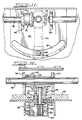
- central drop section 14 is of a box beam configuration providing the desired degree of rigidity to the frame structure. More specifically, the central drop section 14 includes platform 16 having one or more cross bolsters 38 and sidewalls 40 all of which are securely welded to each other to provide what is, in effect, a sturdy load-bearing beam. As illustrated in FIGURE 3, platform 16 is provided with a longitudinally extending slot which defines track 20.
- Each rail bogie 10 is further provided with a trailer securement system.
- the trailer securement system of the present invention comprises a chock assembly 42 and at least two separate and independent chock blocks 44 and 46.
- chock assembly 42 is securable to platform 16 and is normally arranged on one side of the rubber-tired wheels of a truck trailer.
- the chock blocks 44 and 46 are each securable to platform 16 and are both arranged on the opposite side of the rubber-tired wheels of the truck trailer.
- chock assembly 42 includes a transversely spaced pair of joined chock blocks 48 and 50. As illustrated, the chock blocks 48 and 50 are joined by a transverse beam structure 52. Intermediate the chock blocks 48 and 50, the chock assembly 42 is provided with an apparatus 54 for positioning the chock assembly relative to the platform 16. Alternatively, chock assembly could be arranged on a pivotable and translatable plate disposed between the chock assembly 42 and platform 16. Chock assembly 42 is preferably about 2,7 m in width.
- chock blocks 48 and 50 of the chock assembly 42 are substantially identical in structure except that they are mounted on opposite sides of the chock assembly. Because chock blocks 48, 50 are substantially identical, only the details of chock block 48 will be discussed with the understanding that chock block 50 may be similarly constructed.
- each chock block includes two transversely spaced, substantially parallel side panels 56 and 58 defining inner and outer rub rail members.
- Each rub rail member is secured to the beam structure 52.
- each rub rail member laterally extends away from beam structure 52 for a distance of about 0,6 m.
- the distal end of each rub rail member flares outwardly to enhance guiding of the trailer's wheels into the chock assembly 42.
- the outer rub rail member 56 on chock block 48 and the outer rub rail member 56′ on chock block 50 are transversely spaced to guide a trailer's standard 31,10 m tandem axle into the chock assembly by aligning the outside sidewalls of the two outer trailer tires.
- the inner rub rail member 58 on chock block 48 and the inner rub rail member 58′ on chock block 50 are transversely spaced apart to guide a trailer's standard 29,30 m tandem axle into the chock assembly 42 by aligning the inner side walls of the inner two trailer tires.
- Disposed between the rail members 56 and 58 of each chock block is an upwardly extending, arcuate chuck plate 60 which is secured to each of the rub rail members. As seen in FIGURE 10, chuck plate 60 is further supported by the beam structure 52.
- each chock block 48, 50 includes an operator-controlled assembly 62 for securing each end of the chock assembly 42 to the platform 16.
- Each securement assembly 62 is operable between engaged and released positions.
- each securement assembly 62 comprises an endwise movable lock pin 64 and an operator-controlled cammed handle 66. Intermediate its ends, lock pin 64 is linearly guided for endwise movement relative to its associated chock block by a pin retainer 68 secured to an outer surface of an outer rail member. The lowermost end of lock pin 64 is adapted to be received in an aperture or bore 70 defined by platform 16.
- platform 16 defines a plurality of apertures or holes 70 arranged in a longitudially extended line of apertures, each of which are adapted to accommodate the lowermost end of lock pin 64.
- lock pin 64 passes through a pin guide 72 and is pivotally connected to the cammed handle 66.
- guide 72 is secured to an outer surface of an outer rail member.
- Cammed handle 66 and guide 72 cooperate together to control displacement of the lowermost end of the lock pin 64 relative to the platform 16.
- the lowermost end of lock pin 64 may be either engaged with platform 16 in a manner locking the chock assembly 42 against displacement relative platform 16 or disengaged with platform 16 in a manner allowing chock assembly 42 to move relative to the platform 16.
- chock assembly positioning apparatus 54 includes a guide shoe 74 and guide shoe pin 76.
- the guide shoe 74 has an inverted "T" shaped configuration the center leg of which is accommodated for sliding movement in the longitudinally extended track 20.
- one end of a guide shoe pin 76 is accommodated in an aperture 80 defined by guide shoe 74.
- the free end of pin 76 extends upward through a slot 81 defined at the free end of a turn plate 82.
- the opposite end of turn plate 82 is secured to beam structure 52 of chock assembly 42.
- the free end of pin 76 is threadably engaged with a nut 84.
- turn plate 82 is entrapped between nut 84 and guide shoe 74 in a manner securing the chock assembly 42 to platform 16 but permitting relative planar rotation relative thereto.
- Such construction further assures that the chock assembly 42 and, thereby, chock blocks 48, 50 will not become detached from the platform 16.
- the opposed ends of slot 81 in turn plate 82 define positive limit stops for the chock assembly 42.
- chock assembly 42 is permitted free planar pivotal movement on the platform 16 through an arc of movement defined by the extent of slot 81.
- the chock assembly is permitted to move along a predetermined longitudinal path defined by the track 20.
- the guide shoe 74 of the positioning apparatus 54 affects the extent of movement permitted chock assembly 42.
- chock assembly positioning apparatus 54 further includes an operator-controlled drive assembly 90 for drivably moving the chock assembly 42 with its joined pair of chock blocks 48 and 50 in either longitudinal direction.
- drive assembly 90 includes a bevel gear set comprising an engaging pair of beveled gears 92 and 94.
- Beveled gear 92 is connected to a transversely extending shaft 96 between two supports 98 and 100.
- gear 92 is connected to the shaft as with a key or spline connection 102.
- Shaft 96 is journaled for rotation by the supports 98 and 100 which upwardly extend from turn plate 82.
- the ends of shaft 96 transversely extend in opposite directions through the beam structure 52.
- suitable apertures 101 are provided in the beam structure 52 to allow passage of shaft 96.
- each free end of shaft 96 extends beyond the outer rub rail member 56 of the respective chock blocks 48 and 50.
- Each free end of shaft 96 can be provided with a drive hub 104.
- Drive hub 104 defines a plurality of holes 106 radially extending from shaft 96 and a square drive 108 (FIGURE 6) at its end for accommodating the squared end of a driver.
- the other beveled gear 94 is rotatably mounted on the turn plate 82.
- Gear 94 is connected to one end of a rotatably mounted pinion 110.
- Gear 94 is connected to the pinion 110 as with a key or spline connection 112 (FIGURE 12).
- a snap ring 128 prevents upward movement of gear 94 relative to pinion 110.
- the pinion 110 is journaled for rotation relative to the turn plate 82 by a bearing or bushing 114 accommodated within a stepped recess 116 defined by turn plate 82.
- a second bearing or bushing 118 is also provided on the pinion 110 at an axially spaced distance from the first bearing 114.
- a spacer 120 maintains the spacing between bearings 114, 118.
- a pinion gear 122 is provided at the other end of the pinion 110.
- pinion gear 122 is adapted for engagement with at least one stationary rack 124.
- a rack bracket 126 secures rack 124 to a cross bolster 38 of the frame structure 112. Alternative forms of mounting the rack are within the spirit and scope of the present invention.
- Rack bracket 126 can also provide support for a guide bar 127 secured thereto. Guide bar 127 cooperates with bearing 118 in guiding the translatory movement of the chock assembly 42.
- chock blocks 44 and 46 arranged on opposite sides of the trailer's wheels are substantially identical in structure.
- both chock blocks 44 and 46 are pivotally secured to the platform 16 along one side of their respective structures. Because chock blocks 44 and 46 are substantially similar, only the details of chock block 44 will be discussed with the understanding that chock block 46 may be similarly constructed.
- chock block 44 includes a pair of transversely spaced members 130 and 132 defining inner and outer rub rail members.
- Members 130 and 132 normally extend longitudinally of platform 16 and are arranged substantially parallel relative to each other.
- the distal end of each rub rail member flares outwardly to enhance guiding of the trailer's wheels into the chock blocks.
- Disposed between and joining members 130 and 132 is an upwardly extending, arcuate chuck plate 134.
- each chock block 44, 46 is pivotally secured to the platform 16.
- the inner rub rail member of each chock block is provided with an apertured ear 136 transversely extending from the rub rail member 130 toward truck 20.
- a threaded fastener 139 is adapted to pass through the apertured ear 136 and be secured in a fixed chock pivot support 138 provided beneath and secured to the planar platform 16.
- each chock block includes an operator-controlled assembly 140 for securing each chock block against planar relative motion on the platform 16.
- Each securement assembly 140 is operable between engaged and released positions.
- each securement assembly 140 comprises an endwise movable lock pin 142 and an operator-controlled cammed handle 144. Intermediate its ends, lock pin 142 is linearly guided for endwise movement relative to its associated chock block by a pin retainer 146. The lowermost end of lock pin 142 is adapted to be received in an aperture or bore 148 defined by platform 16. The opposite end of lock pin 142 passes through a pin guide 150 and is pivotally connected to the cammed handle 144. Cammed handle 144 and guide 150 cooperate together to control displacement of the lowermost end of lock pin 142 relative to the platform 16.
- the lowermost end of lock pin 142 may be either engaged with platform 16 in a manner locking the chock block against displacement or disengaged with platform 16 in a manner allowing chock block to pivotally move relative to the platform.
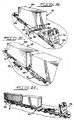
- the semi-trailer ST is of conventional design including a trailer body 154 with a first end defined by left and right rubber-tired wheels 156 and 158 arranged on opposite sides of the trailer body. It will be understood that the trailer body can include one axle or tandem axles, depending on trailer design. As seen in FIGURE 19, a second end of the trailer is defined by a pair of trailer landing legs 160, 162 and a kingpin 164 depending from the trailer body 154.
- Each rail bogie in the consist is endwise movable over a railway section 166.
- the semi-trailer ST is initially loaded onto a rail bogie 10 such that the trailer body 154 is substantially aligned with a longitudinal axis of the frame structure 12 of the rail bogie 10.
- Wheels 156, 158 are arranged on the platform 16 and the second end of the trailer extends longitudinally past the end of the first rail bogie 10.
- the bogie 10 is initially positioned on the railway section 166 adjacent to a loading ramp 170 of a terminal area T with its drop deck section 14 arranged adjacent the ramp.
- the rail bogie may be moved into a position adjacent the ramp 170 through use of either a conventional railroad locomotive or a rubber-tired truck-tractor locomotive which, as will be described, serves a dual purpose and is generally indicated by reference numeral 172 in the drawings.
- the tractor used to move the semi-trailer ST preferably includes a hydraulically actuated fifth wheel assembly on the end opposite a cab and is provided with railroad couplers at its front and rear ends.
- the chock assembly 42 is arranged perpendicular to the loading ramp 170 as illustrated in FIGURE 17.
- the chock block 46 closest to the ramp 170 is preferably rotated at approximately a forty five degree angle bringing it out of the path of the wheels 156, 158 of the trailer ST.
- tractor 172 is disconnected from rail bogie 10 and is connected to the semi-trailer ST.
- the trailer ST is then driven rearwardly up the ramp 170 at an acute angle relative to the straight rail section 166.
- the rear wheels 156, 158 of the trailer are backed into the chock blocks 48 and 50 of the chock assembly 42.
- the chock assembly 42 facilitates simultaneous rotattional movement of the trailer wheels 156, 158 through an arc on the platform 16 and translatory movement of the trailer wheels 156, 158 along a predetermined longitudinal path during semi-trailer loading.
- loading of the trailer ST can include the following intermediate steps. Having once positioned the rail bogie 10 adjacent the ramp 170, the driver takes sufficient steps to prevent the rail bogie 10 from moving endwise on the railway section 166.
- the rail bogie can be prevented from endwise movement by: either using a wheel retaining device at an appropriate end of the rail bogie; or, setting the air brakes on the rail bogie; or, setting a parking brake on the rail bogie.
- the driver then returns to the tractor 172 and proceeds to back the trailer ST up the ramp which rises to the height of the deck section 14.
- the driver continues backing the trailer until the trailer wheels are received in the chock blocks 48 and 50 of the chock assembly 42.
- a hook (not shown), extendable from the rear axle of the trailer, is connected to the chock assembly 42.
- the driver then releases whatever device or means used to lock the rail bogie 10 from endwise movement on the rail section 166. As illustrated in FIGURE 17, the driver then proceeds to start what is known as a "jack knife” maneuver to rotate the trailer body 154 to bring it into line with that of the rail bogie 10. To maneuver the trailer in the manner described, the tractor 172 is turned in the opposite direction as he is backing up both the trailer ST and the rail bogie 10 together.
- the next step involves moving the first rail bogie 10 and the semi-trailer ST until the trailer landing legs 160, 162 are positioned to be supported by a stanchion 174.
- Stanchion 174 is provided adjacent to the railway section 166 and, preferably, on the same side of railway section 166 as the ramp 160.
- Stanchion 174 can take many forms. In its preferred form, and as seen in FIGURES 22-24, stanchion 174 includes a pivotal support 176 extending from a base 178 and having a cantilevered arm 180. Base 178 is securely arranged adjacent the railway section 166.
- Base 178 includes two lock assemblies 182 and 184 arranged orthogonally with respect to each other on the base 178 for holding the stanchion arm 180 in either of two positions.
- Arm 180 includes two transversely spaced support members 186 and 188. Each support member 186, 188 is adapted to accommodate and support one depending trailer leg when arm 180 is pivotally moved from its solid-line position, illustrated in FIGURE 23, to its "loaded” phantom-line position whereat it is ready to bear the weight of the trailer landing legs. Once locked in its "loaded” position, the stanchion 174 will not allow the trailer's landing legs 160, 162 to move.
- the distal end of arm 180 is provided with a depending leg or support 190. Leg 190 contacts the rail in rail section 166 farthest from the pivotal support 176. Thus, arm 180 supports the trailer's weight at two points.
- Lock assemblies 182 and 184 each include a pivotal arm 192 which is pivotally secured to the base 178.
- An extension 194 may project transversely from the arm 192.
- a resilient member 196 or spring normally maintains the arm 192 in an upstruck position.
- a sear 198 is carried on the support arm 180 and is adapted to cooperate with the arm 192 in securing the stanchion in one of its two positions. By pressing downward on the projection 194, the lock is released in a manner allowing the stanchion to be displaced from one position to another.
- the next step in forming the consist involves securing the trailer's wheels 156, 158 on the platform 16 of the rail bogie 10 by entrapping the wheels 156, 158 between the chock assembly 42 and the separate and independent chock blocks 44 and 46.
- the step of securing the trailer to the platform is effected by the operator braking the rail bogie 10 against endwise movement along rail section 166. As mentioned above, this end may be effected in a plurality of ways. Having once secured the rail bogie against endwise movement relative to the rail section 166, the trailer body is moved forward such that the wheels 156, 158 thereof engage the chock blocks 44 and 46. Because the trailer is temporarily connected to the chock assembly 42 through a hook, forward movement of trailer body 154 brings the chock assembly 42 forward therewith. The final positioning of chock assembly 42 may be effected manually through use of drive assembly 90 drivably moving the chocks 48 and 50 toward the opposite side of the trailer wheels 156, 158.
- the next step in the method of loading the semi-trailer onto the railway truck involves lowering the landing legs 160, 162 onto the stanchion's support arm 180 after the arm 180 is positioned beneath the landing legs 160, 162.
- the landing legs 160, 162 of the trailer are brought down as far as they will go (typically, about twenty inches).
- the fifth wheel assembly on the tractor 172 is then lowered until the sand shoes or bottom parts of the landing legs 160, 162 of the trailer rest on the stanchion's support arm 180.
- the driver then uncouples the tractor 172 from the trailer ST.
- the next step in the method of loading the semi-trailer onto the railway truck involves moving a second loaded rail bogie 10′ toward the first rail bogie 10 until a fifth wheel assembly 36′ on the second rail bogie 10′ lockably engages the kingpin 164 on the trailer body 154 in a manner forming the consist.
- the second rail bogie 10′ Before the second rail bogie 10′ is connected to the first rail bogie 10, an empty rail bogie 10′ is arranged relative the ramp 170 of the terminal area T and another semi-trailer ST is loaded in the same manner as described above. Thereafter, the second rail bogie 10′ is moved along with the semi-trailer thereon into position for coupling with the first rail bogie 10. Ultimately, and as described above, the fifth wheel assembly 36′ on the second rail bogie 10′ lockably engages the kingpin 164 on the trailer body secured to rail bogie 10. When the coupling is positive, the landing legs 160, 162 on trailer body 154 of the first rail bogie are raised, just enough to take the weight off the rotating stanchion arm 180.
- the second rail bogie 10′ is then pushed backward until the landing legs on the trailer body carried by the second rail bogie 10′ are positioned to be supported by the stanchion arm 180. Thereafter, the stanchion arm 180 is again swung out and the landing legs are lowered from the second trailer body and the tractor is again uncoupled from rail bogie 10′. This procedure is repeated until all the trailers are loaded onto the consist.
- the unloading procedure is quite nearly the reverse of the loading procedure and as such will not be dealt with here. Understandably, a person skilled in the art and the experience gained in first loading the consist will immediately make the unloading process, and many possible unthought variations, clear to the performance of these ends.
Landscapes
- Engineering & Computer Science (AREA)
- Transportation (AREA)
- Mechanical Engineering (AREA)
- Handcart (AREA)
- Automobile Manufacture Line, Endless Track Vehicle, Trailer (AREA)
- Train Traffic Observation, Control, And Security (AREA)
Claims (12)
- In einem System zum Schienentransport eines Sattelaufliegers für Straßenfahrzeuge mit gummibereiften Laufrädern, wobei der Sattelauflieger zwischen ersten und zweiten Schienen-Drehgestellen (10) getragen ist, und jedes der genannten Schienen-Drehgestelle umfaßt:
eine Tiefladebrücke (12), die auf Radachsen (26) abgestützt ist, die nahe gegenüberliegender Enden derselben positioniert sind, wobei die Ladebrücke einen mittleren Tiefladeteil (14) bildet, der eine ortsfeste, sich längs erstreckende, ebene Plattform (16) aufweist, welche eine Oberseite (18) zum Tragen der Räder (28) des genannten Sattelaufliegers bildet; und
ein Aufliegerbefestigungssystem, bestehend aus einer Bremsblockanordnung (42) zum Erleichtern der gleichzeitigen Drehbewegung der genannten Sattelaufliegerräder (28) über einen Bogen auf der Plattform (16) und eine translatorische Bewegung der genannten Räder (28) entlang einer vorbestimmten, sich längs erstreckenden Bahn auf der Plattform (16), wobei die Bremsblockanordnung (42) ein im Abstand quer angeordnetes Paar von miteinander verbundenen Bremsblöcken (48, 50) umfaßt, die normalerweise auf einer Seite der genannten Sattelaufliegerräder (28) angeordnet sind, wobei jeder der genannten Bremsblöcke (48, 50) Mittel zur Befestigung der Bremsblöcke (48, 50) an der Plattform (16) umfaßt, derart, daß die genannten Sattelaufliegerräder (28) in einer ersten, sich längs erstreckenden Richtung gegen Bewegung gesichert sind, und Mittel zum Positionieren der genannten Bremsblockanordnung (42) auf der genannten Plattform (16), derart, daß eine Bewegung der genannten Bremsblockanordnung (42) um eine im wesentlichen senkrechte Achse und entlang einer vorbestimmten, sich längs erstrekkenden Bahn begrenzt wird; und mindestens zwei getrennte und unabhängige Bremsblöcke (44, 46), von denen jeder Mittel zum Befestigen der genannten getrennten und unabhängigen Bremsblöcke (44, 46) an der genannten Plattform (16) an einer gegenüberliegenden Seite der genannten Sattelaufliegerräder (28) aufweist, derart, daß die genannten Sattelaufliegerräder (28) gegen Bewegung in einer zweiten Längsrichtung gesichert sind. - Die Erfindung nach Anspruch 1, bei der die Tiefladebrücke (12) Plattform-Endflächen (22, 24) bildet, die oberhalb der genannten, mit Rädern versehenen Achsen (26) positioniert sind.
- Die Erfindung nach Anspruch 2, bei der mindestens eine der Plattform-Endflächen (22, 24) eine Sattelkupplung (36) aufweist, die oberhalb derselben abgestützt ist.
- Die Erfindung nach Anspruch 1, bei der jeder Bremsblock der genannten Bremsblockanordnung (42) ein Paar quer beabstandeter, sich in Längsrichtung erstreckender Teile umfaßt, die innere und äußere, parallele Gleitschienenteile (56, 56' 58, 58') bilden.
- Die Erfindung nach Anspruch 1, bei der die genannte Befestigungsvorrichtung an jedem der genannten Bremsblöcke (44, 46, 48, 50) einen elastisch vorgespannten Zapfen (64) umfaßt, der in ein Loch (70) eingreift, das von der genannten Plattform (16) gebildet ist.
- Die Erfindung nach Anspruch 1, bei der die genannte Positioniervorrichtung einen Schwenkzapfen (76) umfaßt, der in einer sich längs erstreckenden Spur (20) verschiebbar aufgenommen ist, welche die vorbestimmte Bahn der Längsbewegung der Bremsblockanordnung (42) bestimmt.
- Die Erfindung nach Anspruch 6, bei der die genannte Spur (20) von der genannten Plattform (16) gebildet ist.
- Die Erfindung nach Anspruch 1, bei der das genannte Positioniermittel ferner Mittel (90) für die antriebsweise Bewegung der genannten Bremsblockanordnung (42) mit dem genannten, miteinander verbundenen Paar von Bremsblöcken (48, 50) in beiden Längsrichtungen umfaßt.
- Die Erfindung nach Anspruch 7, bei der das genannte treibende Mittel eine Zahnstangen- und Zahnritzelanordnung (124, 122) umfaßt.
- Die Erfindung nach Anspruch 1, bei der jeder der getrennten und unabhängigen Bremsblöcke an der Plattform (16) schwenkbar befestigt ist.
- Verfahren zum Bilden einer zusammengesetzten Anordnung, bestehend aus einem Straßen-Sattelauflieger, getragen zwischen ersten und zweiten Schienen-Drehgestellen, wobei jedes Schienen-Drehgestell endweise über einen schienenabschnitt bewegbar ist und einen mittleren Tiefladeteil hat, der eine ortsfeste Plattform bildet, der genannte Straßen-Sattelauflieger einen Aufliegerkörper hat, ein erstes Ende von linken und rechten Gummireifenrädern gebildet ist, die auf gegenüberliegenden Seiten des Aufliegerkörpers angeordnet sind, und ein zweites Ende Aufliegerstützfüße sowie einen Königszapfen hat, der von dem Aufliegerkörper abwärts ragt, wobei das genannte Verfahren die Schritte umfaßt:(a) Laden des genannten Sattelaufliegers auf das genannte erste Schienen-Drehgestell, derart, daß der genannte Aufliegerkörper im wesentlichen zu einer Längsachse des genannten Tiefladeteils ausgerichtet wird und die genannten Räder auf der genannten ortsfesten Plattform hat, wobei das genannte zweite Ende sich in Längsrichtung an einem Ende des genannten ersten Schienen-Drehgestells vorbei erstreckt, das genannte erste Schienen-Drehgestell eine hintere Bremsblockanordnung umfaßt, in die die genannten Räder hineinpassen, die genannte hintere Bremsblockanordnung die gleichzeitige Drehbewegung der genannten Räder über einen Bogen auf der Plattform sowie eine translatorische Bewegung der genannten Räder entlang einer vorbestimmten, sich längs erstreckenden Bahn während des Ladens des Sattelaufliegers erleichtert;(b) Bewegen des genannten ersten Schienen-Drehgestelles und des genannten Sattelaufliegers, bis die genannten Sattelauflieger-Stützfüße so positioniert sind, daß sie durch eine Runge abstützbar sind, die in der Nähe des genannten Eisenbahnschienenabschnitts vorgesehen ist, wobei die genannte Runge einen beweglich angebrachten Tragarm aufweist;(c) Befestigen der genannten Räder an der genannten Plattform durch Festlegen der genannten Räder zwischen der genannten hinteren Bremsblockanordnung sowie den getrennten und unabhängigen, vorderen Bremsblöcken, wobei die genannten vorderen Bremsblöcke in Längsrichtung an der genannten Plattform festgelegt sind;(d) Absenken der Stützfüße auf den Stützarm der Runge, nachdem der genannte Arm unter den genannten Stützfüßen positioniert ist; und(e) Bewegen des genannten zweiten Schienen-Drehgestells in Richtung des genannten ersten Schienen-Drehgestells, bis eine Königszapfenanordnung auf dem genannten zweiten Schienen-Drehgestell den Königszapfen auf dem genannten Sattelaufliegerkörper in einer Weise sperrend erfaßt, durch die die genannte zusammengesetzte Anordnung gebildet wird.
- Verfahren nach Anspruch 11, bei dem das Laden des genannten Sattelaufliegers gemäß Schritt (a) die weiteren Schritte des Positionierens des genannten ersten Schienen-Drehgestells mit dem genannten mittleren Tiefladeteil auf dem genannten Eisenbahnabschnitt und relativ zu einem Stationsbereich mit einer Rampe umfaßt, wobei der genannte Eisenbahnschienenabschnitt sich entlang einer im wesentlichen geradlinigen Bahn und in der Nähe des genannten Stationsbereiches erstreckt; Bewegen des genannten ersten Endes des genannten Sattelaufliegers auf die Rampe des Stationsbereichs in einem spitzen Winkel in bezug auf den Eisenbahnschienenabschnitt, bis die genannten Räder in die genannte hintere Bremsblockanordnung hineinpassen; sowie Drehen des Sattelaufliegerkörpers in eine wesentliche Ausrichtung zu der Längsachse des Tiefladeteils, während das genannte erste Schienen-Drehgestell und der genannte Sattelaufliegerkörper gleichzeitig bewegt werden.
Priority Applications (1)
| Application Number | Priority Date | Filing Date | Title |
|---|---|---|---|
| AT89106539T ATE94487T1 (de) | 1988-04-13 | 1989-04-12 | Intermodales sattelaufliegertransportsystem auf zwei schienenfahrzeugen. |
Applications Claiming Priority (2)
| Application Number | Priority Date | Filing Date | Title |
|---|---|---|---|
| US181207 | 1988-04-13 | ||
| US07/181,207 US4838744A (en) | 1988-04-13 | 1988-04-13 | Intermodal system for transporting a semi-trailer on two railway vehicles |
Publications (3)
| Publication Number | Publication Date |
|---|---|
| EP0337437A2 EP0337437A2 (de) | 1989-10-18 |
| EP0337437A3 EP0337437A3 (en) | 1990-03-07 |
| EP0337437B1 true EP0337437B1 (de) | 1993-09-15 |
Family
ID=22663331
Family Applications (1)
| Application Number | Title | Priority Date | Filing Date |
|---|---|---|---|
| EP89106539A Expired - Lifetime EP0337437B1 (de) | 1988-04-13 | 1989-04-12 | Intermodales Sattelaufliegertransportsystem auf zwei Schienenfahrzeugen |
Country Status (7)
| Country | Link |
|---|---|
| US (1) | US4838744A (de) |
| EP (1) | EP0337437B1 (de) |
| AT (1) | ATE94487T1 (de) |
| CA (1) | CA1310543C (de) |
| DE (1) | DE68909087D1 (de) |
| IN (1) | IN172076B (de) |
| ZA (1) | ZA892521B (de) |
Families Citing this family (9)
| Publication number | Priority date | Publication date | Assignee | Title |
|---|---|---|---|---|
| SE520032C2 (sv) * | 2002-05-24 | 2003-05-13 | Sjoelanders Smides Och Mek Ver | Fordon för körning på såväl väg som järnvägsspår |
| US7954437B2 (en) * | 2007-05-17 | 2011-06-07 | Freightcar America, Inc. | Railroad well car with open truss sides |
| US8757067B2 (en) | 2007-05-17 | 2014-06-24 | JAC Operations, Inc | Railroad well car with open truss sides |
| US20090151596A1 (en) * | 2007-12-12 | 2009-06-18 | William Harvey Sproat | Fastload rail carrier for motor vehicles, freight and passengers |
| CN102056751B (zh) * | 2008-06-13 | 2013-04-03 | 卡特彼勒路面机械公司 | 转向架锁 |
| DE102012008292A1 (de) | 2012-04-17 | 2013-10-17 | Matthias Berger | Transportsystem |
| CN107792107B (zh) * | 2016-08-28 | 2024-08-09 | 中车青岛四方机车车辆股份有限公司 | 轨道车辆商务车厢的车窗结构及轨道车辆 |
| CN111977297B (zh) * | 2019-05-21 | 2021-12-14 | 捷普电子(新加坡)公司 | 输送装置 |
| CN112721971B (zh) * | 2020-12-31 | 2024-12-24 | 欧特美交通科技股份有限公司 | 一种肋排式贯通道渡板装置 |
Family Cites Families (13)
| Publication number | Priority date | Publication date | Assignee | Title |
|---|---|---|---|---|
| US3581918A (en) * | 1968-01-12 | 1971-06-01 | Fruehauf Corp | Railcar-unloading system |
| DE1948283A1 (de) * | 1969-09-24 | 1971-04-01 | A T Kearney & Company Inc | Eisenbahnzug fuer Huckepack-Transport |
| AR194165A1 (es) * | 1972-06-26 | 1973-06-22 | Gutehoffnungshuette Sterkrade | Mezcladora movil para transporte de arrabio liquido |
| US3841511A (en) * | 1973-11-19 | 1974-10-15 | J Haun | Transport system and apparatus therefor |
| US4179997A (en) * | 1977-12-23 | 1979-12-25 | Intermodal Concepts, Inc. | Rail-highway intermodal freight carrier transport system |
| US4416571A (en) * | 1981-02-17 | 1983-11-22 | Krause Robert A | Truck and rail transportation system |
| US4397243A (en) * | 1981-03-02 | 1983-08-09 | A. F. Hickman Associates, Inc. | Convertible highway railroad vehicle |
| US4561011A (en) * | 1982-10-05 | 1985-12-24 | Mitsubishi Denki Kabushiki Kaisha | Dimensionally stable semiconductor device |
| GB2147551B (en) * | 1983-09-30 | 1988-05-18 | Baker Dorian R W | Road/rail intermodal transport |
| CA1234723A (en) * | 1985-06-26 | 1988-04-05 | Ronald F. Woollam | Low level freight car |
| US4665834A (en) * | 1985-08-16 | 1987-05-19 | Sea-Land Service Inc. | Apparatus for intermodal transport of highway containers |
| US4671714A (en) * | 1985-08-16 | 1987-06-09 | Bennett Robert W | System for transporting semi-trailers on two interconnected vehicles |
| US4688140A (en) * | 1985-10-28 | 1987-08-18 | John Hammes | Electronic defensive weapon |
-
1988
- 1988-04-13 US US07/181,207 patent/US4838744A/en not_active Expired - Fee Related
-
1989
- 1989-04-03 CA CA000595551A patent/CA1310543C/en not_active Expired - Lifetime
- 1989-04-04 IN IN262/MAS/89A patent/IN172076B/en unknown
- 1989-04-05 ZA ZA892521A patent/ZA892521B/xx unknown
- 1989-04-12 DE DE89106539T patent/DE68909087D1/de not_active Expired - Lifetime
- 1989-04-12 AT AT89106539T patent/ATE94487T1/de active
- 1989-04-12 EP EP89106539A patent/EP0337437B1/de not_active Expired - Lifetime
Also Published As
| Publication number | Publication date |
|---|---|
| US4838744A (en) | 1989-06-13 |
| EP0337437A3 (en) | 1990-03-07 |
| EP0337437A2 (de) | 1989-10-18 |
| CA1310543C (en) | 1992-11-24 |
| DE68909087D1 (de) | 1993-10-21 |
| ATE94487T1 (de) | 1993-10-15 |
| ZA892521B (en) | 1989-12-27 |
| IN172076B (de) | 1993-03-27 |
Similar Documents
| Publication | Publication Date | Title |
|---|---|---|
| US4179997A (en) | Rail-highway intermodal freight carrier transport system | |
| US3317219A (en) | Vehicle formed by coupleable containers with demountable adapter frames | |
| US4669391A (en) | Train of highway trailers | |
| US2841094A (en) | System of transporting highway vehicles by rail | |
| US4129079A (en) | Railroad car for highway trailers | |
| CA1182066A (en) | Railway car turntable loading system | |
| US4773336A (en) | Railroad bogie for removably supporting coupled semi-trailers | |
| AU685442B2 (en) | Intermodal vehicle for forming train or trailers | |
| CA1088123A (en) | Multiple hook-up, movable axle, container cargo trailer | |
| US4111451A (en) | Multi-trailer, dolly-connected, movable-axle, containerized cargo trailer system | |
| EP0138450A1 (de) | Intermodaltransport | |
| CN100360359C (zh) | 用于半拖车或两机动车的铁路/公路联运的铁路装置 | |
| US2959428A (en) | Trailer assembly | |
| US5017064A (en) | Intermodal transport system | |
| EP0337437B1 (de) | Intermodales Sattelaufliegertransportsystem auf zwei Schienenfahrzeugen | |
| US4955292A (en) | Dual-mode rail-highway semi-trailer with separable bogie | |
| US4111450A (en) | Multiple hook-up, movable axle trailer with removable track extensions, slidable kingpin, and pivotal axle assemblies | |
| CA2058755A1 (en) | Ramp systems for assembling and disassembling highway trailers and railtrucks for intermodal transportation | |
| US2638852A (en) | Rail trailer carrier | |
| US2010969A (en) | Semitrailer | |
| US4766818A (en) | Train of highway trailers and method of making | |
| US4653966A (en) | Drop-deck intermodal bogie | |
| EP1539513B1 (de) | Für verschiedene fahrmodi ausgeführtes fahrzeug und verfahren zum fahren solcher fahrzeuge | |
| US5009169A (en) | Twin axle rail bogie for convertible rail-highway vehicles | |
| US5601030A (en) | Railraod bogie, for connecting vehicles in an articulated train |
Legal Events
| Date | Code | Title | Description |
|---|---|---|---|
| PUAI | Public reference made under article 153(3) epc to a published international application that has entered the european phase |
Free format text: ORIGINAL CODE: 0009012 |
|
| AK | Designated contracting states |
Kind code of ref document: A2 Designated state(s): AT BE CH DE ES FR GB GR IT LI LU NL SE |
|
| PUAL | Search report despatched |
Free format text: ORIGINAL CODE: 0009013 |
|
| AK | Designated contracting states |
Kind code of ref document: A3 Designated state(s): AT BE CH DE ES FR GB GR IT LI LU NL SE |
|
| 17P | Request for examination filed |
Effective date: 19900831 |
|
| 17Q | First examination report despatched |
Effective date: 19921104 |
|
| GRAA | (expected) grant |
Free format text: ORIGINAL CODE: 0009210 |
|
| AK | Designated contracting states |
Kind code of ref document: B1 Designated state(s): AT BE CH DE ES FR GB GR IT LI LU NL SE |
|
| PG25 | Lapsed in a contracting state [announced via postgrant information from national office to epo] |
Ref country code: IT Free format text: LAPSE BECAUSE OF FAILURE TO SUBMIT A TRANSLATION OF THE DESCRIPTION OR TO PAY THE FEE WITHIN THE PRE;WARNING: LAPSES OF ITALIAN PATENTS WITH EFFECTIVE DATE BEFORE 2007 MAY HAVE OCCURRED AT ANY TIME BEFORE 2007. THE CORRECT EFFECTIVE DATE MAY BE DIFFERENT FROM THE ONE RECORDED.SCRIBED TIME-LIMIT Effective date: 19930915 Ref country code: FR Effective date: 19930915 Ref country code: AT Effective date: 19930915 Ref country code: BE Effective date: 19930915 Ref country code: CH Effective date: 19930915 Ref country code: DE Effective date: 19930915 Ref country code: NL Effective date: 19930915 Ref country code: SE Effective date: 19930915 Ref country code: GR Free format text: LAPSE BECAUSE OF FAILURE TO SUBMIT A TRANSLATION OF THE DESCRIPTION OR TO PAY THE FEE WITHIN THE PRESCRIBED TIME-LIMIT Effective date: 19930915 Ref country code: LI Effective date: 19930915 Ref country code: ES Free format text: THE PATENT HAS BEEN ANNULLED BY A DECISION OF A NATIONAL AUTHORITY Effective date: 19930915 |
|
| REF | Corresponds to: |
Ref document number: 94487 Country of ref document: AT Date of ref document: 19931015 Kind code of ref document: T |
|
| REF | Corresponds to: |
Ref document number: 68909087 Country of ref document: DE Date of ref document: 19931021 |
|
| REG | Reference to a national code |
Ref country code: CH Ref legal event code: PL |
|
| EN | Fr: translation not filed | ||
| NLV1 | Nl: lapsed or annulled due to failure to fulfill the requirements of art. 29p and 29m of the patents act | ||
| PG25 | Lapsed in a contracting state [announced via postgrant information from national office to epo] |
Ref country code: GB Effective date: 19940412 |
|
| PG25 | Lapsed in a contracting state [announced via postgrant information from national office to epo] |
Ref country code: LU Free format text: LAPSE BECAUSE OF NON-PAYMENT OF DUE FEES Effective date: 19940430 |
|
| PLBE | No opposition filed within time limit |
Free format text: ORIGINAL CODE: 0009261 |
|
| STAA | Information on the status of an ep patent application or granted ep patent |
Free format text: STATUS: NO OPPOSITION FILED WITHIN TIME LIMIT |
|
| 26N | No opposition filed | ||
| GBPC | Gb: european patent ceased through non-payment of renewal fee |
Effective date: 19940412 |