EP0337437B1 - Intermodal system for transporting a semi-trailer on two railway vehicles - Google Patents
Intermodal system for transporting a semi-trailer on two railway vehicles Download PDFInfo
- Publication number
- EP0337437B1 EP0337437B1 EP89106539A EP89106539A EP0337437B1 EP 0337437 B1 EP0337437 B1 EP 0337437B1 EP 89106539 A EP89106539 A EP 89106539A EP 89106539 A EP89106539 A EP 89106539A EP 0337437 B1 EP0337437 B1 EP 0337437B1
- Authority
- EP
- European Patent Office
- Prior art keywords
- trailer
- semi
- chock
- platform
- wheels
- Prior art date
- Legal status (The legal status is an assumption and is not a legal conclusion. Google has not performed a legal analysis and makes no representation as to the accuracy of the status listed.)
- Expired - Lifetime
Links
Images


Classifications
-
- B—PERFORMING OPERATIONS; TRANSPORTING
- B60—VEHICLES IN GENERAL
- B60F—VEHICLES FOR USE BOTH ON RAIL AND ON ROAD; AMPHIBIOUS OR LIKE VEHICLES; CONVERTIBLE VEHICLES
- B60F1/00—Vehicles for use both on rail and on road; Conversions therefor
- B60F1/04—Vehicles for use both on rail and on road; Conversions therefor with rail and road wheels on different axles
- B60F1/046—Semi-trailer or trailer type vehicles without own propelling units
Definitions
- the present invention generally relates to railway rolling stock and, more particularly, to a system for transporting highway semi-trailers, and the like, by rail.
- the inability of railroads to effectively compete in a shorter distance market stems from two factors.
- the first factor involves the problem of matching the lengths of the semi-trailers to the flat cars.
- flat cars are available in lengths ranging from 12,19 m to 27.43 m and more, a fairly significant number are in the 24.38 to 27.43 m range.
- Semi-trailers are also available in a variety of lengths, but a significant number are in the 12.19 to 15.24 m range. Thus, it is fairly common that semi-trailers must be transported one on one because they are too long for double, tandem loading on available flat rolling stock.
- the second problem concerns the prohibitive capital costs and operating expenses associated with the loading of trailers on today's railroad flat cars. Because of terminal costs associated with loading and unloading the trailers on flat cars, railroads find it difficult to absorb such terminal costs while remaining competitive with road freight services.
- Such system uses improved rail bogies as the sole support of adjacent rear and front ends of the trailer and as the sole connecting means between such trailers, to form trains.
- the patented system includes a rail bogie having a frame structure supported on wheeled axles positioned at the respective ends of the frame structure.
- the frame structure defines a pair of end deck surfaces positioned above the wheeled axles and a central drop deck surface disposed between and below the end deck surfaces.
- a fifth wheel assembly is supported above each of the end deck surfaces for receipt of a kingpin of a semi-trailer.
- a deck plate member is pivotally secured to the drop deck surface for planar rotation with respect thereto about a substantially vertical axis.
- a pair of transversely spaced, longitudinally extending, internal and external rub rail members extend upwardly from the drop deck plate member for receipt of semi-trailer tandems therebetween.
- the drop deck plate is movable between first and second positions. In one position, the rub rail members on the deck plate are substantially parallel to the longitudinal axis of the frame structure. When in its second position, the rub rail members on the deck plate member are substantially perpendicular to the longitudinal axis of the frame structure.
- a semi-trailer extends between a pair of adjacent bogies.
- the tandems of the trailer are received and supported on the drop deck plate between the corresponding rub rail members of a first bogie and the kingpin of the trailer is received and supported on the fifth wheel assembly of the immediately adjacent bogie.
- the procedure for loading and unloading the semi-trailers onto and from the bogies is facilitated by the rotating drop deck plate.
- This system is limited in its ability to secure a semi-trailer against endwise displacement relative to the deck plate member. Separate devices need to be provided to secure the semi-trailer tandems relative to the deck plate. Should such securement devices become dislodged during transportation, a trailer may be allowed or permitted an unwanted freedom of movement relative to the deck plate.
- a system for transporting by rail a highway semi-trailer, or the like In accordance with this invention, a front end of the semi-trailer is supported by and connected to a first rail bogie. The semi-trailer's rubber-tired, wheeled end is supported by and connected to a second rail bogie.
- the system of the present invention permits hauling of any conventional highway trailer from 8,54 m to 18,30 m in length. Moreover, the structure of each rail bogie lends itself to simple and shortened loading and unloading procedures.
- a salient feature of the present system is a rail bogie having a drop deck frame structure supported on wheeled axles positioned adjacent opposite ends of the frame structure.
- the frame structure defines a central drop deck section having a stationary, longitudinally extended, planar platform defining an upper surface for supporting the highway wheels of a semi-trailer.
- Standard railroad car couplers are provided at opposite ends of the frame structure.
- Each rail bogie of the present invention further includes its own trailer securement system comprising a chock assembly normally arranged on one side of the semi-trailer's wheels and at least two separate and independent chock block means arranged on an opposite side of the semi-trailer's wheels.
- the chock assembly facilitates simultaneous rotational movement of the semi-trailer's wheels through an arc on the platform and translatory movement of the wheels along a predetermined longitudinal path on the platform.
- the chock assembly includes a transversely spaced pair of joined chock block means each of which includes securement devices for holding the chock block means stationary relative to the platform in a manner securing the semi-trailer's wheels against movement in a first longitudinal direction.
- the chock assembly further includes a positioning apparatus for limiting movement of the chock assembly on the platform about a substantially vertical axis and along a predetermined longitudinal path.
- Each of the separate and independent chock block means include securement devices for holding them stationary relative to the platform on the opposite side of the semi-trailer's wheels.
- Each of these separate chock block means secure the semi-trailer's wheels against movement in a second longitudinal direction.
- the drop deck frame structure of each rail bogie further defines end deck surfaces positioned above the wheeled axles.
- the planar platform defined by the central drop section is disposed beneath the end deck surfaces and between the wheeled axles. At least one of the end deck surfaces on the frame structure has a fifth wheel assembly supported thereabove.
- An expedient embodiment of the present invention has a chock assembly which includes a transverse beam structure for joining the pairs of chock block means to opposite ends thereof.
- Each of the chock block means of the chock assembly includes a pair of transversely spaced, longitudinally extending members defining inner and outer parallel rub rail members.
- each securement device on the chock assembly includes a pin which engages with an aperture or hole defined by the platform.
- a cammed handle is connected to the pin and controls its operative effectiveness.
- the platform preferably defines a plurality of holes arranged in a longitudinally extended line which permit the trailer securement system to be adaptable to trailers having various length tandums.
- the positioning apparatus of the chock assembly includes a pivot pin which is slidably received in a longitudinally extending track. This track defines a predetermined path of longitudinal movement of the chock assembly and is defined on the platform.
- the positioning apparatus further includes an apparatus for drivably moving the chock assembly with the joined pair of chock block means in either longitudinal direction along the track.
- the driving apparatus in a preferred form of the invention, includes a rack and pinion arrangement. Such rack and pinion arrangement further includes operator-controlled means for longitudinally positioning the chock assembly on the platform. In a preferred embodiment, the rack is secured to the platform and the pinion is secured to the chock assembly.
- the positioning apparatus further includes positive stops for limiting planar rotation of the chock assembly relative to the platform.
- each separate and independent chock block means is pivotally secured to the platform.
- each separate and independent chock block includes a pair of transversely spaced, longitudinally extending members defining inner and outer rub rail members.
- the present invention further concerns a method for forming a consist comprising a highway semi-trailer whose body is lengthwise supported between two rail bogies of the above-described type.
- the semi-trailer body has a first end defined by left and right rubber-tired wheels arranged on opposite sides of the trailer body.
- a second end of the trailer body is defined by a pair of trailer landing legs and a kingpin suspended from the trailer body.
- the method for forming the consist involves an initial step of loading the semi-trailer onto a first rail bogie.
- the trailer is loaded such that the trailer body thereof is substantially aligned with the longitudinal axis of the frame section and has the rubber-tired wheels thereof on the stationary platform with its second end longitudinally extending past an end of the first rail bogie.
- the rail bogie includes a chock assembly into which the left and right trailer wheels fit.
- the chock assembly facilitates simultaneous rotational movement of the wheels through an arc on the platform and translatory movement of those wheels along a predetermined longitudinal path during semi-trailer loading.
- loading of the semi-trailer according to the present invention further comprises a step of positioning the first rail bogie with its central drop deck frame on a railway section relative to a terminal area with a ramp.
- the railway section extends along a substantially straight line path and adjacent the terminal area.
- Loading of the semi-trailer further includes the steps of moving the first end of the semi-trailer up the terminal area ramp at an acute angle relative to the railway section until the trailer's wheels fit into the chock assembly. Thereafter, the trailer body is turned into substantial alignment with the longitudinal axis of the frame section of the rail bogie while simultaneously moving the first rail bogie and the trailer body. It should be appreciated, however, that the first rail bogie is held against moving relative to the railway section until the wheels fit into the chock assembly.
- the first rail bogie and the semi-trailer are moved until the trailer's landing legs are positioned to be supported by a stanchion provided adjacent the railway section.
- the stanchion has a movably mounted support arm.
- the wheels of the trailer are secured to the platform.
- the wheels are secured to the platform of the rail bogie by entrapping the wheels between the chock assembly and the separate and independent front chock block means.
- the separate and independent chock block means are longitudinally secured to the platform and the chock assembly is longitudinally moved in a manner securing the trailer's wheels.
- the trailer's landing legs are lowered onto the stanchion support arm after the arm is positioned beneath the landing legs.
- the support arm of the stanchion will carry the weight of the front of the semi-trailer as distributed through its landing legs.
- a second loaded rail bogie is moved toward the first rail bogie until the fifth wheel assembly on the second rail bogie lockably engages the kingpin on the trailer body in a manner forming the consist.
- the present invention concerns an intermodal system which permits railroads to transport truck trailers of any length.
- a salient feature of this system is a rail bogie 10.
- each rail bogie 10 includes a drop deck frame structure 12.
- the frame structure 12 defines a central drop deck section 14 having a stationary, longitudinally extending planar platform 16.
- Platform 16 defines an upper surface 18 and a longitudinally extending track 20 extending substantially coaxial with the longitudinal axis of frame structure 12.
- Frame structure 12 further defines end deck surfaces 22 and 24 arranged at opposite ends of deck section 14.
- Preferably, frame structure 12 is about 9 m in length and about 2,7 m in width.
- Platform 16 is disposed beneath end deck surfaces 22 and 24 and measures about 3,6 m in length and about 2,7 m in width.
- Frame structure 12 is supported in a suitable manner above a pair of spaced apart wheeled axles 26 positioned below end deck surfaces 22 and 24.
- the planar platform 16 is disposed between axles 26.
- Wheeled axles 26 preferably include railroad wheels 28 of a standard 8,54 m with the axles rotating within conventional roller bearing journal boxes 30 and suspended by conventional rail springs 32.
- Each rail bogie is further provided with suitable brake rigging, valves and reservoirs which conform to A.A.R./F.R.A. Standards. Standard A.A.R. type couplers 34 are provided at each end of frame structure 12.
- At least one fifth-wheel assembly 36 is secured to one end deck surface 22 or 24.
- the specific configuration of the fifth wheel does not form an integral part of the present invention.
- the fifth-wheel assembly 36 is of a fixed height.
- central drop section 14 is of a box beam configuration providing the desired degree of rigidity to the frame structure. More specifically, the central drop section 14 includes platform 16 having one or more cross bolsters 38 and sidewalls 40 all of which are securely welded to each other to provide what is, in effect, a sturdy load-bearing beam. As illustrated in FIGURE 3, platform 16 is provided with a longitudinally extending slot which defines track 20.
- Each rail bogie 10 is further provided with a trailer securement system.
- the trailer securement system of the present invention comprises a chock assembly 42 and at least two separate and independent chock blocks 44 and 46.
- chock assembly 42 is securable to platform 16 and is normally arranged on one side of the rubber-tired wheels of a truck trailer.
- the chock blocks 44 and 46 are each securable to platform 16 and are both arranged on the opposite side of the rubber-tired wheels of the truck trailer.
- chock assembly 42 includes a transversely spaced pair of joined chock blocks 48 and 50. As illustrated, the chock blocks 48 and 50 are joined by a transverse beam structure 52. Intermediate the chock blocks 48 and 50, the chock assembly 42 is provided with an apparatus 54 for positioning the chock assembly relative to the platform 16. Alternatively, chock assembly could be arranged on a pivotable and translatable plate disposed between the chock assembly 42 and platform 16. Chock assembly 42 is preferably about 2,7 m in width.
- chock blocks 48 and 50 of the chock assembly 42 are substantially identical in structure except that they are mounted on opposite sides of the chock assembly. Because chock blocks 48, 50 are substantially identical, only the details of chock block 48 will be discussed with the understanding that chock block 50 may be similarly constructed.
- each chock block includes two transversely spaced, substantially parallel side panels 56 and 58 defining inner and outer rub rail members.
- Each rub rail member is secured to the beam structure 52.
- each rub rail member laterally extends away from beam structure 52 for a distance of about 0,6 m.
- the distal end of each rub rail member flares outwardly to enhance guiding of the trailer's wheels into the chock assembly 42.
- the outer rub rail member 56 on chock block 48 and the outer rub rail member 56′ on chock block 50 are transversely spaced to guide a trailer's standard 31,10 m tandem axle into the chock assembly by aligning the outside sidewalls of the two outer trailer tires.
- the inner rub rail member 58 on chock block 48 and the inner rub rail member 58′ on chock block 50 are transversely spaced apart to guide a trailer's standard 29,30 m tandem axle into the chock assembly 42 by aligning the inner side walls of the inner two trailer tires.
- Disposed between the rail members 56 and 58 of each chock block is an upwardly extending, arcuate chuck plate 60 which is secured to each of the rub rail members. As seen in FIGURE 10, chuck plate 60 is further supported by the beam structure 52.
- each chock block 48, 50 includes an operator-controlled assembly 62 for securing each end of the chock assembly 42 to the platform 16.
- Each securement assembly 62 is operable between engaged and released positions.
- each securement assembly 62 comprises an endwise movable lock pin 64 and an operator-controlled cammed handle 66. Intermediate its ends, lock pin 64 is linearly guided for endwise movement relative to its associated chock block by a pin retainer 68 secured to an outer surface of an outer rail member. The lowermost end of lock pin 64 is adapted to be received in an aperture or bore 70 defined by platform 16.
- platform 16 defines a plurality of apertures or holes 70 arranged in a longitudially extended line of apertures, each of which are adapted to accommodate the lowermost end of lock pin 64.
- lock pin 64 passes through a pin guide 72 and is pivotally connected to the cammed handle 66.
- guide 72 is secured to an outer surface of an outer rail member.
- Cammed handle 66 and guide 72 cooperate together to control displacement of the lowermost end of the lock pin 64 relative to the platform 16.
- the lowermost end of lock pin 64 may be either engaged with platform 16 in a manner locking the chock assembly 42 against displacement relative platform 16 or disengaged with platform 16 in a manner allowing chock assembly 42 to move relative to the platform 16.
- chock assembly positioning apparatus 54 includes a guide shoe 74 and guide shoe pin 76.
- the guide shoe 74 has an inverted "T" shaped configuration the center leg of which is accommodated for sliding movement in the longitudinally extended track 20.
- one end of a guide shoe pin 76 is accommodated in an aperture 80 defined by guide shoe 74.
- the free end of pin 76 extends upward through a slot 81 defined at the free end of a turn plate 82.
- the opposite end of turn plate 82 is secured to beam structure 52 of chock assembly 42.
- the free end of pin 76 is threadably engaged with a nut 84.
- turn plate 82 is entrapped between nut 84 and guide shoe 74 in a manner securing the chock assembly 42 to platform 16 but permitting relative planar rotation relative thereto.
- Such construction further assures that the chock assembly 42 and, thereby, chock blocks 48, 50 will not become detached from the platform 16.
- the opposed ends of slot 81 in turn plate 82 define positive limit stops for the chock assembly 42.
- chock assembly 42 is permitted free planar pivotal movement on the platform 16 through an arc of movement defined by the extent of slot 81.
- the chock assembly is permitted to move along a predetermined longitudinal path defined by the track 20.
- the guide shoe 74 of the positioning apparatus 54 affects the extent of movement permitted chock assembly 42.
- chock assembly positioning apparatus 54 further includes an operator-controlled drive assembly 90 for drivably moving the chock assembly 42 with its joined pair of chock blocks 48 and 50 in either longitudinal direction.
- drive assembly 90 includes a bevel gear set comprising an engaging pair of beveled gears 92 and 94.
- Beveled gear 92 is connected to a transversely extending shaft 96 between two supports 98 and 100.
- gear 92 is connected to the shaft as with a key or spline connection 102.
- Shaft 96 is journaled for rotation by the supports 98 and 100 which upwardly extend from turn plate 82.
- the ends of shaft 96 transversely extend in opposite directions through the beam structure 52.
- suitable apertures 101 are provided in the beam structure 52 to allow passage of shaft 96.
- each free end of shaft 96 extends beyond the outer rub rail member 56 of the respective chock blocks 48 and 50.
- Each free end of shaft 96 can be provided with a drive hub 104.
- Drive hub 104 defines a plurality of holes 106 radially extending from shaft 96 and a square drive 108 (FIGURE 6) at its end for accommodating the squared end of a driver.
- the other beveled gear 94 is rotatably mounted on the turn plate 82.
- Gear 94 is connected to one end of a rotatably mounted pinion 110.
- Gear 94 is connected to the pinion 110 as with a key or spline connection 112 (FIGURE 12).
- a snap ring 128 prevents upward movement of gear 94 relative to pinion 110.
- the pinion 110 is journaled for rotation relative to the turn plate 82 by a bearing or bushing 114 accommodated within a stepped recess 116 defined by turn plate 82.
- a second bearing or bushing 118 is also provided on the pinion 110 at an axially spaced distance from the first bearing 114.
- a spacer 120 maintains the spacing between bearings 114, 118.
- a pinion gear 122 is provided at the other end of the pinion 110.
- pinion gear 122 is adapted for engagement with at least one stationary rack 124.
- a rack bracket 126 secures rack 124 to a cross bolster 38 of the frame structure 112. Alternative forms of mounting the rack are within the spirit and scope of the present invention.
- Rack bracket 126 can also provide support for a guide bar 127 secured thereto. Guide bar 127 cooperates with bearing 118 in guiding the translatory movement of the chock assembly 42.
- chock blocks 44 and 46 arranged on opposite sides of the trailer's wheels are substantially identical in structure.
- both chock blocks 44 and 46 are pivotally secured to the platform 16 along one side of their respective structures. Because chock blocks 44 and 46 are substantially similar, only the details of chock block 44 will be discussed with the understanding that chock block 46 may be similarly constructed.
- chock block 44 includes a pair of transversely spaced members 130 and 132 defining inner and outer rub rail members.
- Members 130 and 132 normally extend longitudinally of platform 16 and are arranged substantially parallel relative to each other.
- the distal end of each rub rail member flares outwardly to enhance guiding of the trailer's wheels into the chock blocks.
- Disposed between and joining members 130 and 132 is an upwardly extending, arcuate chuck plate 134.
- each chock block 44, 46 is pivotally secured to the platform 16.
- the inner rub rail member of each chock block is provided with an apertured ear 136 transversely extending from the rub rail member 130 toward truck 20.
- a threaded fastener 139 is adapted to pass through the apertured ear 136 and be secured in a fixed chock pivot support 138 provided beneath and secured to the planar platform 16.
- each chock block includes an operator-controlled assembly 140 for securing each chock block against planar relative motion on the platform 16.
- Each securement assembly 140 is operable between engaged and released positions.
- each securement assembly 140 comprises an endwise movable lock pin 142 and an operator-controlled cammed handle 144. Intermediate its ends, lock pin 142 is linearly guided for endwise movement relative to its associated chock block by a pin retainer 146. The lowermost end of lock pin 142 is adapted to be received in an aperture or bore 148 defined by platform 16. The opposite end of lock pin 142 passes through a pin guide 150 and is pivotally connected to the cammed handle 144. Cammed handle 144 and guide 150 cooperate together to control displacement of the lowermost end of lock pin 142 relative to the platform 16.
- the lowermost end of lock pin 142 may be either engaged with platform 16 in a manner locking the chock block against displacement or disengaged with platform 16 in a manner allowing chock block to pivotally move relative to the platform.
- the semi-trailer ST is of conventional design including a trailer body 154 with a first end defined by left and right rubber-tired wheels 156 and 158 arranged on opposite sides of the trailer body. It will be understood that the trailer body can include one axle or tandem axles, depending on trailer design. As seen in FIGURE 19, a second end of the trailer is defined by a pair of trailer landing legs 160, 162 and a kingpin 164 depending from the trailer body 154.
- Each rail bogie in the consist is endwise movable over a railway section 166.
- the semi-trailer ST is initially loaded onto a rail bogie 10 such that the trailer body 154 is substantially aligned with a longitudinal axis of the frame structure 12 of the rail bogie 10.
- Wheels 156, 158 are arranged on the platform 16 and the second end of the trailer extends longitudinally past the end of the first rail bogie 10.
- the bogie 10 is initially positioned on the railway section 166 adjacent to a loading ramp 170 of a terminal area T with its drop deck section 14 arranged adjacent the ramp.
- the rail bogie may be moved into a position adjacent the ramp 170 through use of either a conventional railroad locomotive or a rubber-tired truck-tractor locomotive which, as will be described, serves a dual purpose and is generally indicated by reference numeral 172 in the drawings.
- the tractor used to move the semi-trailer ST preferably includes a hydraulically actuated fifth wheel assembly on the end opposite a cab and is provided with railroad couplers at its front and rear ends.
- the chock assembly 42 is arranged perpendicular to the loading ramp 170 as illustrated in FIGURE 17.
- the chock block 46 closest to the ramp 170 is preferably rotated at approximately a forty five degree angle bringing it out of the path of the wheels 156, 158 of the trailer ST.
- tractor 172 is disconnected from rail bogie 10 and is connected to the semi-trailer ST.
- the trailer ST is then driven rearwardly up the ramp 170 at an acute angle relative to the straight rail section 166.
- the rear wheels 156, 158 of the trailer are backed into the chock blocks 48 and 50 of the chock assembly 42.
- the chock assembly 42 facilitates simultaneous rotattional movement of the trailer wheels 156, 158 through an arc on the platform 16 and translatory movement of the trailer wheels 156, 158 along a predetermined longitudinal path during semi-trailer loading.
- loading of the trailer ST can include the following intermediate steps. Having once positioned the rail bogie 10 adjacent the ramp 170, the driver takes sufficient steps to prevent the rail bogie 10 from moving endwise on the railway section 166.
- the rail bogie can be prevented from endwise movement by: either using a wheel retaining device at an appropriate end of the rail bogie; or, setting the air brakes on the rail bogie; or, setting a parking brake on the rail bogie.
- the driver then returns to the tractor 172 and proceeds to back the trailer ST up the ramp which rises to the height of the deck section 14.
- the driver continues backing the trailer until the trailer wheels are received in the chock blocks 48 and 50 of the chock assembly 42.
- a hook (not shown), extendable from the rear axle of the trailer, is connected to the chock assembly 42.
- the driver then releases whatever device or means used to lock the rail bogie 10 from endwise movement on the rail section 166. As illustrated in FIGURE 17, the driver then proceeds to start what is known as a "jack knife” maneuver to rotate the trailer body 154 to bring it into line with that of the rail bogie 10. To maneuver the trailer in the manner described, the tractor 172 is turned in the opposite direction as he is backing up both the trailer ST and the rail bogie 10 together.
- the next step involves moving the first rail bogie 10 and the semi-trailer ST until the trailer landing legs 160, 162 are positioned to be supported by a stanchion 174.
- Stanchion 174 is provided adjacent to the railway section 166 and, preferably, on the same side of railway section 166 as the ramp 160.
- Stanchion 174 can take many forms. In its preferred form, and as seen in FIGURES 22-24, stanchion 174 includes a pivotal support 176 extending from a base 178 and having a cantilevered arm 180. Base 178 is securely arranged adjacent the railway section 166.
- Base 178 includes two lock assemblies 182 and 184 arranged orthogonally with respect to each other on the base 178 for holding the stanchion arm 180 in either of two positions.
- Arm 180 includes two transversely spaced support members 186 and 188. Each support member 186, 188 is adapted to accommodate and support one depending trailer leg when arm 180 is pivotally moved from its solid-line position, illustrated in FIGURE 23, to its "loaded” phantom-line position whereat it is ready to bear the weight of the trailer landing legs. Once locked in its "loaded” position, the stanchion 174 will not allow the trailer's landing legs 160, 162 to move.
- the distal end of arm 180 is provided with a depending leg or support 190. Leg 190 contacts the rail in rail section 166 farthest from the pivotal support 176. Thus, arm 180 supports the trailer's weight at two points.
- Lock assemblies 182 and 184 each include a pivotal arm 192 which is pivotally secured to the base 178.
- An extension 194 may project transversely from the arm 192.
- a resilient member 196 or spring normally maintains the arm 192 in an upstruck position.
- a sear 198 is carried on the support arm 180 and is adapted to cooperate with the arm 192 in securing the stanchion in one of its two positions. By pressing downward on the projection 194, the lock is released in a manner allowing the stanchion to be displaced from one position to another.
- the next step in forming the consist involves securing the trailer's wheels 156, 158 on the platform 16 of the rail bogie 10 by entrapping the wheels 156, 158 between the chock assembly 42 and the separate and independent chock blocks 44 and 46.
- the step of securing the trailer to the platform is effected by the operator braking the rail bogie 10 against endwise movement along rail section 166. As mentioned above, this end may be effected in a plurality of ways. Having once secured the rail bogie against endwise movement relative to the rail section 166, the trailer body is moved forward such that the wheels 156, 158 thereof engage the chock blocks 44 and 46. Because the trailer is temporarily connected to the chock assembly 42 through a hook, forward movement of trailer body 154 brings the chock assembly 42 forward therewith. The final positioning of chock assembly 42 may be effected manually through use of drive assembly 90 drivably moving the chocks 48 and 50 toward the opposite side of the trailer wheels 156, 158.
- the next step in the method of loading the semi-trailer onto the railway truck involves lowering the landing legs 160, 162 onto the stanchion's support arm 180 after the arm 180 is positioned beneath the landing legs 160, 162.
- the landing legs 160, 162 of the trailer are brought down as far as they will go (typically, about twenty inches).
- the fifth wheel assembly on the tractor 172 is then lowered until the sand shoes or bottom parts of the landing legs 160, 162 of the trailer rest on the stanchion's support arm 180.
- the driver then uncouples the tractor 172 from the trailer ST.
- the next step in the method of loading the semi-trailer onto the railway truck involves moving a second loaded rail bogie 10′ toward the first rail bogie 10 until a fifth wheel assembly 36′ on the second rail bogie 10′ lockably engages the kingpin 164 on the trailer body 154 in a manner forming the consist.
- the second rail bogie 10′ Before the second rail bogie 10′ is connected to the first rail bogie 10, an empty rail bogie 10′ is arranged relative the ramp 170 of the terminal area T and another semi-trailer ST is loaded in the same manner as described above. Thereafter, the second rail bogie 10′ is moved along with the semi-trailer thereon into position for coupling with the first rail bogie 10. Ultimately, and as described above, the fifth wheel assembly 36′ on the second rail bogie 10′ lockably engages the kingpin 164 on the trailer body secured to rail bogie 10. When the coupling is positive, the landing legs 160, 162 on trailer body 154 of the first rail bogie are raised, just enough to take the weight off the rotating stanchion arm 180.
- the second rail bogie 10′ is then pushed backward until the landing legs on the trailer body carried by the second rail bogie 10′ are positioned to be supported by the stanchion arm 180. Thereafter, the stanchion arm 180 is again swung out and the landing legs are lowered from the second trailer body and the tractor is again uncoupled from rail bogie 10′. This procedure is repeated until all the trailers are loaded onto the consist.
- the unloading procedure is quite nearly the reverse of the loading procedure and as such will not be dealt with here. Understandably, a person skilled in the art and the experience gained in first loading the consist will immediately make the unloading process, and many possible unthought variations, clear to the performance of these ends.
Landscapes
- Engineering & Computer Science (AREA)
- Transportation (AREA)
- Mechanical Engineering (AREA)
- Handcart (AREA)
- Train Traffic Observation, Control, And Security (AREA)
- Automobile Manufacture Line, Endless Track Vehicle, Trailer (AREA)
Abstract
Description
- The present invention generally relates to railway rolling stock and, more particularly, to a system for transporting highway semi-trailers, and the like, by rail.
- Several systems have been proposed to implement intermodal transfer over long distances as a commercially viable alternative to wholly road freight services which are available. Such systems include "piggy back" transport of road semi-trailers, complete lorries, or other land-moving vehicles on conventional railroad flat cars of sufficient length to support the length of one or two of such vehicles or containers.
- The cost advantage enjoyed by long distance rail transportation of semi-trailers and the like on railroad flat cars is well known and recognized by industry. It has been recognized, however, that there are inefficiencies inherent in the basic concept of transporting semi-trailers or the like on railway flat cars for shorter distances, i.e., less than 500 miles.
- The inability of railroads to effectively compete in a shorter distance market stems from two factors. The first factor involves the problem of matching the lengths of the semi-trailers to the flat cars. Although flat cars are available in lengths ranging from 12,19 m to 27.43 m and more, a fairly significant number are in the 24.38 to 27.43 m range. Semi-trailers are also available in a variety of lengths, but a significant number are in the 12.19 to 15.24 m range. Thus, it is fairly common that semi-trailers must be transported one on one because they are too long for double, tandem loading on available flat rolling stock. Thus, except where the railroad flat cars are matched with semi-trailers either approximately equal to or approximately half their lengths, piggy back transportation of semi-trailers tends to be somewhat inefficient because relatively large amounts of space are wasted and unoccupied in one-on-one loadings.
- The second problem concerns the prohibitive capital costs and operating expenses associated with the loading of trailers on today's railroad flat cars. Because of terminal costs associated with loading and unloading the trailers on flat cars, railroads find it difficult to absorb such terminal costs while remaining competitive with road freight services.
- U.S. Patent US-A- 4,653,966, assigned to the same assignee as the instant application, discloses a unique system for transporting highway semi-trailers, or the like, by rail. Such system uses improved rail bogies as the sole support of adjacent rear and front ends of the trailer and as the sole connecting means between such trailers, to form trains.
- The patented system includes a rail bogie having a frame structure supported on wheeled axles positioned at the respective ends of the frame structure. The frame structure defines a pair of end deck surfaces positioned above the wheeled axles and a central drop deck surface disposed between and below the end deck surfaces. A fifth wheel assembly is supported above each of the end deck surfaces for receipt of a kingpin of a semi-trailer. A deck plate member is pivotally secured to the drop deck surface for planar rotation with respect thereto about a substantially vertical axis. A pair of transversely spaced, longitudinally extending, internal and external rub rail members extend upwardly from the drop deck plate member for receipt of semi-trailer tandems therebetween.
- As disclosed, the drop deck plate is movable between first and second positions. In one position, the rub rail members on the deck plate are substantially parallel to the longitudinal axis of the frame structure. When in its second position, the rub rail members on the deck plate member are substantially perpendicular to the longitudinal axis of the frame structure.
- In accordance with that system, a semi-trailer extends between a pair of adjacent bogies. The tandems of the trailer are received and supported on the drop deck plate between the corresponding rub rail members of a first bogie and the kingpin of the trailer is received and supported on the fifth wheel assembly of the immediately adjacent bogie. The procedure for loading and unloading the semi-trailers onto and from the bogies is facilitated by the rotating drop deck plate.
- The system as disclosed in U.S. Patent No. 4,653,966 has improved upon the prior system in that it allows for the straddling of a semi-trailer between two bogies or short flat cars, thus permitting the trailer frame rails to distribute longitudinal stress. Also, this system provides a timely procedure for loading and unloading the semi-trailers onto and from the bogies.
- This system, however, is limited in its ability to secure a semi-trailer against endwise displacement relative to the deck plate member. Separate devices need to be provided to secure the semi-trailer tandems relative to the deck plate. Should such securement devices become dislodged during transportation, a trailer may be allowed or permitted an unwanted freedom of movement relative to the deck plate.
- In view of the above, and in accordance with the present invention, there is provided a system for transporting by rail a highway semi-trailer, or the like. In accordance with this invention, a front end of the semi-trailer is supported by and connected to a first rail bogie. The semi-trailer's rubber-tired, wheeled end is supported by and connected to a second rail bogie. The system of the present invention permits hauling of any conventional highway trailer from 8,54 m to 18,30 m in length. Moreover, the structure of each rail bogie lends itself to simple and shortened loading and unloading procedures.
- A salient feature of the present system is a rail bogie having a drop deck frame structure supported on wheeled axles positioned adjacent opposite ends of the frame structure. The frame structure defines a central drop deck section having a stationary, longitudinally extended, planar platform defining an upper surface for supporting the highway wheels of a semi-trailer. Standard railroad car couplers are provided at opposite ends of the frame structure.
- Each rail bogie of the present invention further includes its own trailer securement system comprising a chock assembly normally arranged on one side of the semi-trailer's wheels and at least two separate and independent chock block means arranged on an opposite side of the semi-trailer's wheels. During the loading procedure, the chock assembly facilitates simultaneous rotational movement of the semi-trailer's wheels through an arc on the platform and translatory movement of the wheels along a predetermined longitudinal path on the platform.
- The chock assembly includes a transversely spaced pair of joined chock block means each of which includes securement devices for holding the chock block means stationary relative to the platform in a manner securing the semi-trailer's wheels against movement in a first longitudinal direction. The chock assembly further includes a positioning apparatus for limiting movement of the chock assembly on the platform about a substantially vertical axis and along a predetermined longitudinal path.
- Each of the separate and independent chock block means include securement devices for holding them stationary relative to the platform on the opposite side of the semi-trailer's wheels. Each of these separate chock block means secure the semi-trailer's wheels against movement in a second longitudinal direction.
- In a preferred form of the invention, the drop deck frame structure of each rail bogie further defines end deck surfaces positioned above the wheeled axles. In such structure, the planar platform defined by the central drop section is disposed beneath the end deck surfaces and between the wheeled axles. At least one of the end deck surfaces on the frame structure has a fifth wheel assembly supported thereabove.
- An expedient embodiment of the present invention has a chock assembly which includes a transverse beam structure for joining the pairs of chock block means to opposite ends thereof. Each of the chock block means of the chock assembly includes a pair of transversely spaced, longitudinally extending members defining inner and outer parallel rub rail members.
- In a prefered form, each securement device on the chock assembly includes a pin which engages with an aperture or hole defined by the platform. A cammed handle is connected to the pin and controls its operative effectiveness. The platform preferably defines a plurality of holes arranged in a longitudinally extended line which permit the trailer securement system to be adaptable to trailers having various length tandums.
- The positioning apparatus of the chock assembly includes a pivot pin which is slidably received in a longitudinally extending track. This track defines a predetermined path of longitudinal movement of the chock assembly and is defined on the platform.
- The positioning apparatus further includes an apparatus for drivably moving the chock assembly with the joined pair of chock block means in either longitudinal direction along the track. The driving apparatus, in a preferred form of the invention, includes a rack and pinion arrangement. Such rack and pinion arrangement further includes operator-controlled means for longitudinally positioning the chock assembly on the platform. In a preferred embodiment, the rack is secured to the platform and the pinion is secured to the chock assembly. The positioning apparatus further includes positive stops for limiting planar rotation of the chock assembly relative to the platform.
- According to a preferred embodiment, each separate and independent chock block means is pivotally secured to the platform. Moreover, each separate and independent chock block includes a pair of transversely spaced, longitudinally extending members defining inner and outer rub rail members.
- The present invention further concerns a method for forming a consist comprising a highway semi-trailer whose body is lengthwise supported between two rail bogies of the above-described type. The semi-trailer body has a first end defined by left and right rubber-tired wheels arranged on opposite sides of the trailer body. A second end of the trailer body is defined by a pair of trailer landing legs and a kingpin suspended from the trailer body.
- The method for forming the consist involves an initial step of loading the semi-trailer onto a first rail bogie. The trailer is loaded such that the trailer body thereof is substantially aligned with the longitudinal axis of the frame section and has the rubber-tired wheels thereof on the stationary platform with its second end longitudinally extending past an end of the first rail bogie.
- As described above, the rail bogie includes a chock assembly into which the left and right trailer wheels fit. During loading, the chock assembly facilitates simultaneous rotational movement of the wheels through an arc on the platform and translatory movement of those wheels along a predetermined longitudinal path during semi-trailer loading.
- In a preferred method, loading of the semi-trailer according to the present invention further comprises a step of positioning the first rail bogie with its central drop deck frame on a railway section relative to a terminal area with a ramp. The railway section extends along a substantially straight line path and adjacent the terminal area.
- Loading of the semi-trailer further includes the steps of moving the first end of the semi-trailer up the terminal area ramp at an acute angle relative to the railway section until the trailer's wheels fit into the chock assembly. Thereafter, the trailer body is turned into substantial alignment with the longitudinal axis of the frame section of the rail bogie while simultaneously moving the first rail bogie and the trailer body. It should be appreciated, however, that the first rail bogie is held against moving relative to the railway section until the wheels fit into the chock assembly.
- After the semi-trailer is substantially aligned with the longitudinal axis of the frame section, the first rail bogie and the semi-trailer are moved until the trailer's landing legs are positioned to be supported by a stanchion provided adjacent the railway section. The stanchion has a movably mounted support arm.
- Having moved the first rail bogie and semi-trailer into position relative the stanchion, the wheels of the trailer are secured to the platform. The wheels are secured to the platform of the rail bogie by entrapping the wheels between the chock assembly and the separate and independent front chock block means. In a preferred form of the invention, the separate and independent chock block means are longitudinally secured to the platform and the chock assembly is longitudinally moved in a manner securing the trailer's wheels.
- Thereafter, the trailer's landing legs are lowered onto the stanchion support arm after the arm is positioned beneath the landing legs. The support arm of the stanchion will carry the weight of the front of the semi-trailer as distributed through its landing legs.
- Thereafter, a second loaded rail bogie is moved toward the first rail bogie until the fifth wheel assembly on the second rail bogie lockably engages the kingpin on the trailer body in a manner forming the consist.
- Other features and advantages of the present invention will become readily apparent from the following detailed description, appended drawings, and the accompanying claims.
-
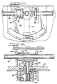
- FIGURE 1 is a side elevational view of a rail bogie constructed in accordance with the present invention, with a rear portion of a semi-trailer schematically represented thereon in broken lines;
- FIGURE 2 is a top plan view of the rail bogie illustrated in FIGURE 1;
- FIGURE 3 is a fragmentary sectional view taken along line 3-3 of FIGURE 2;
- FIGURE 4 is an enlarged top plan view of a chock assembly according to the present invention;
- FIGURE 5 is a front elevational view of the chock assembly illustrated in FIGURE 4;
- FIGURE 6 is a right side elevational view of the chock assembly illustrated in FIGURE 4;
- FIGURE 7 is a partial sectional view taken along line 7-7 of FIGURE 4;
- FIGURE 8 is a partial sectional view taken along line 8-8 of FIGURE 4;
- FIGURE 9 is a partial sectional view taken along line 9-9 of FIGURE 4;
- FIGURE 10 is a partial sectional view taken along line 10-10 of FIGURE 4;
- FIGURE 11 is a sectional view taken along line 11-11 of FIGURE 8;
- FIGURE 12 is a longitudinal sectional view taken along line 12-12 of FIGURE 11;
- FIGURE 13 is a top plan view of another chock block used in combination with the present invention;
- FIGURE 14 is a left side elevational view of the chock block illustrated in FIGURE 13;
- FIGURE 15 is an enlarged fragmentary view of a portion of the chock block illustrated in FIGURE 13;
- FIGURE 16 is a sectional view taken along line 16-16 of FIGURE 15;
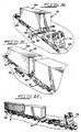
- FIGURES 17-21 are schematic perspective views depicting sequential loading of a semi-trailer between a pair of rail bogies constructed in accordance with the present invention;
- FIGURE 22 is a perspective view of a stationary stanchion used during the loading process;
- FIGURE 23 is a top plan view of the stanchion illustrated in FIGURE 22 shown in two positions; and
- FIGURE 24 is a front elevational view of the stanchion constructed in accordance with the present invention.
- While the present invention is susceptible of embodiment of various forms, there is shown in the drawings a presently preferred embodiment hereinafter described, with the understanding that the present disclosure is to be considered as an exemplification of the invention, and is not intended to limit the invention to the specific embodiment illustrated.
- Referring now to the drawings wherein like reference numerals indicate like parts throughout the several views, the present invention concerns an intermodal system which permits railroads to transport truck trailers of any length. A salient feature of this system is a
rail bogie 10. - As seen in FIGURES 1 and 2, each
rail bogie 10 includes a dropdeck frame structure 12. Theframe structure 12 defines a centraldrop deck section 14 having a stationary, longitudinally extendingplanar platform 16.Platform 16 defines anupper surface 18 and alongitudinally extending track 20 extending substantially coaxial with the longitudinal axis offrame structure 12.Frame structure 12 further defines end deck surfaces 22 and 24 arranged at opposite ends ofdeck section 14. Preferably,frame structure 12 is about 9 m in length and about 2,7 m in width.Platform 16 is disposed beneath end deck surfaces 22 and 24 and measures about 3,6 m in length and about 2,7 m in width. -
Frame structure 12 is supported in a suitable manner above a pair of spaced apart wheeledaxles 26 positioned below end deck surfaces 22 and 24. Theplanar platform 16 is disposed betweenaxles 26.Wheeled axles 26 preferably includerailroad wheels 28 of a standard 8,54 m with the axles rotating within conventional rollerbearing journal boxes 30 and suspended by conventional rail springs 32. Each rail bogie is further provided with suitable brake rigging, valves and reservoirs which conform to A.A.R./F.R.A. Standards. Standard A.A.R.type couplers 34 are provided at each end offrame structure 12. - At least one fifth-
wheel assembly 36 is secured to oneend deck surface wheel assembly 36 is of a fixed height. - As seen in FIGURE 3,
central drop section 14 is of a box beam configuration providing the desired degree of rigidity to the frame structure. More specifically, thecentral drop section 14 includesplatform 16 having one or more cross bolsters 38 andsidewalls 40 all of which are securely welded to each other to provide what is, in effect, a sturdy load-bearing beam. As illustrated in FIGURE 3,platform 16 is provided with a longitudinally extending slot which definestrack 20. - Each
rail bogie 10 is further provided with a trailer securement system. The trailer securement system of the present invention comprises achock assembly 42 and at least two separate and independent chock blocks 44 and 46. As seen in FIGURES 1 and 2, chockassembly 42 is securable toplatform 16 and is normally arranged on one side of the rubber-tired wheels of a truck trailer. The chock blocks 44 and 46 are each securable toplatform 16 and are both arranged on the opposite side of the rubber-tired wheels of the truck trailer. - As best illustrated in FIGURES 4 and 5, chock
assembly 42 includes a transversely spaced pair of joined chock blocks 48 and 50. As illustrated, the chock blocks 48 and 50 are joined by atransverse beam structure 52. Intermediate the chock blocks 48 and 50, thechock assembly 42 is provided with anapparatus 54 for positioning the chock assembly relative to theplatform 16. Alternatively, chock assembly could be arranged on a pivotable and translatable plate disposed between thechock assembly 42 andplatform 16.Chock assembly 42 is preferably about 2,7 m in width. - As seen in FIGURE 4, the chock blocks 48 and 50 of the
chock assembly 42 are substantially identical in structure except that they are mounted on opposite sides of the chock assembly. Because chock blocks 48, 50 are substantially identical, only the details ofchock block 48 will be discussed with the understanding that chockblock 50 may be similarly constructed. - As seen in FIGURE 4, each chock block includes two transversely spaced, substantially
parallel side panels beam structure 52. Moreover, each rub rail member laterally extends away frombeam structure 52 for a distance of about 0,6 m. In a preferred form, the distal end of each rub rail member flares outwardly to enhance guiding of the trailer's wheels into thechock assembly 42. - The outer
rub rail member 56 onchock block 48 and the outerrub rail member 56′ onchock block 50 are transversely spaced to guide a trailer's standard 31,10 m tandem axle into the chock assembly by aligning the outside sidewalls of the two outer trailer tires. The innerrub rail member 58 onchock block 48 and the innerrub rail member 58′ onchock block 50 are transversely spaced apart to guide a trailer's standard 29,30 m tandem axle into thechock assembly 42 by aligning the inner side walls of the inner two trailer tires. Disposed between therail members arcuate chuck plate 60 which is secured to each of the rub rail members. As seen in FIGURE 10,chuck plate 60 is further supported by thebeam structure 52. - In a preferred form of the invention, each chock
block assembly 62 for securing each end of thechock assembly 42 to theplatform 16. Eachsecurement assembly 62 is operable between engaged and released positions. - As seen in FIGURE 6, each
securement assembly 62 comprises an endwisemovable lock pin 64 and an operator-controlledcammed handle 66. Intermediate its ends,lock pin 64 is linearly guided for endwise movement relative to its associated chock block by apin retainer 68 secured to an outer surface of an outer rail member. The lowermost end oflock pin 64 is adapted to be received in an aperture or bore 70 defined byplatform 16. In a preferred form of the invention, and as seen in FIGURE 2,platform 16 defines a plurality of apertures or holes 70 arranged in a longitudially extended line of apertures, each of which are adapted to accommodate the lowermost end oflock pin 64. - Returning to FIGURE 6, the opposite end of
lock pin 64 passes through apin guide 72 and is pivotally connected to thecammed handle 66. Likepin retainer 68, guide 72 is secured to an outer surface of an outer rail member. Cammed handle 66 and guide 72 cooperate together to control displacement of the lowermost end of thelock pin 64 relative to theplatform 16. As a function of the disposition ofhandle 66, the lowermost end oflock pin 64 may be either engaged withplatform 16 in a manner locking thechock assembly 42 against displacementrelative platform 16 or disengaged withplatform 16 in a manner allowingchock assembly 42 to move relative to theplatform 16. - In its preferred form, and as seen in FIGURES 8 and 11, chock
assembly positioning apparatus 54 includes aguide shoe 74 and guideshoe pin 76. Theguide shoe 74 has an inverted "T" shaped configuration the center leg of which is accommodated for sliding movement in the longitudinally extendedtrack 20. As best illustrated in FIGURE 8, one end of aguide shoe pin 76 is accommodated in anaperture 80 defined byguide shoe 74. The free end ofpin 76 extends upward through aslot 81 defined at the free end of aturn plate 82. The opposite end ofturn plate 82 is secured tobeam structure 52 ofchock assembly 42. The free end ofpin 76 is threadably engaged with anut 84. By such construction,turn plate 82 is entrapped betweennut 84 and guideshoe 74 in a manner securing thechock assembly 42 toplatform 16 but permitting relative planar rotation relative thereto. Such construction further assures that thechock assembly 42 and, thereby, chock blocks 48, 50 will not become detached from theplatform 16. - As seen in FIGURE 11, the opposed ends of
slot 81 inturn plate 82 define positive limit stops for thechock assembly 42. When eachsecurement assembly 62 on thechock assembly 42 is released, chockassembly 42 is permitted free planar pivotal movement on theplatform 16 through an arc of movement defined by the extent ofslot 81. Moreover, when eachsecurement assembly 62 is released, the chock assembly is permitted to move along a predetermined longitudinal path defined by thetrack 20. Here again, theguide shoe 74 of thepositioning apparatus 54 affects the extent of movement permittedchock assembly 42. - In a preferred form of the invention, chock
assembly positioning apparatus 54 further includes an operator-controlleddrive assembly 90 for drivably moving thechock assembly 42 with its joined pair of chock blocks 48 and 50 in either longitudinal direction. As illustrated in FIGURES 11 and 12,drive assembly 90 includes a bevel gear set comprising an engaging pair of beveled gears 92 and 94.Beveled gear 92 is connected to a transversely extendingshaft 96 between twosupports gear 92 is connected to the shaft as with a key orspline connection 102.Shaft 96 is journaled for rotation by thesupports turn plate 82. The ends ofshaft 96 transversely extend in opposite directions through thebeam structure 52. As seen in FIGURES 9 and 10, suitable apertures 101 are provided in thebeam structure 52 to allow passage ofshaft 96. - As seen in FIGURE 4, each free end of
shaft 96 extends beyond the outerrub rail member 56 of the respective chock blocks 48 and 50. Each free end ofshaft 96 can be provided with adrive hub 104.Drive hub 104 defines a plurality ofholes 106 radially extending fromshaft 96 and a square drive 108 (FIGURE 6) at its end for accommodating the squared end of a driver. - As best seen in FIGURES 7, 8 and 12, the other
beveled gear 94 is rotatably mounted on theturn plate 82.Gear 94 is connected to one end of a rotatably mountedpinion 110.Gear 94 is connected to thepinion 110 as with a key or spline connection 112 (FIGURE 12). A snap ring 128 prevents upward movement ofgear 94 relative topinion 110. Thepinion 110 is journaled for rotation relative to theturn plate 82 by a bearing or bushing 114 accommodated within a steppedrecess 116 defined byturn plate 82. A second bearing orbushing 118 is also provided on thepinion 110 at an axially spaced distance from the first bearing 114. A spacer 120 maintains the spacing betweenbearings 114, 118. Apinion gear 122 is provided at the other end of thepinion 110. - As best illustrated in FIGURES 8 and 12,
pinion gear 122 is adapted for engagement with at least onestationary rack 124. As seen in FIGURE 12, arack bracket 126 securesrack 124 to a cross bolster 38 of theframe structure 112. Alternative forms of mounting the rack are within the spirit and scope of the present invention.Rack bracket 126 can also provide support for a guide bar 127 secured thereto. Guide bar 127 cooperates with bearing 118 in guiding the translatory movement of thechock assembly 42. - Chock blocks 44 and 46, arranged on opposite sides of the trailer's wheels are substantially identical in structure. In the preferred embodiment, both chock blocks 44 and 46 are pivotally secured to the
platform 16 along one side of their respective structures. Because chock blocks 44 and 46 are substantially similar, only the details ofchock block 44 will be discussed with the understanding that chockblock 46 may be similarly constructed. - As seen in FIGURE 13,
chock block 44 includes a pair of transversely spacedmembers Members platform 16 and are arranged substantially parallel relative to each other. In a preferred form of the invention, the distal end of each rub rail member flares outwardly to enhance guiding of the trailer's wheels into the chock blocks. Disposed between and joiningmembers arcuate chuck plate 134. - Each
chock block platform 16. As seen in FIGURES 13, 15 and 16, the inner rub rail member of each chock block is provided with anapertured ear 136 transversely extending from therub rail member 130 towardtruck 20. A threaded fastener 139 is adapted to pass through theapertured ear 136 and be secured in a fixedchock pivot support 138 provided beneath and secured to theplanar platform 16. By such construction, each separate andindependent chock block platform 16 without becoming detached therefrom. - The opposite
rub rail member 132 of each chock block includes an operator-controlledassembly 140 for securing each chock block against planar relative motion on theplatform 16. Eachsecurement assembly 140 is operable between engaged and released positions. - As best seen in FIGURE 14, each
securement assembly 140 comprises an endwisemovable lock pin 142 and an operator-controlledcammed handle 144. Intermediate its ends,lock pin 142 is linearly guided for endwise movement relative to its associated chock block by apin retainer 146. The lowermost end oflock pin 142 is adapted to be received in an aperture or bore 148 defined byplatform 16. The opposite end oflock pin 142 passes through apin guide 150 and is pivotally connected to thecammed handle 144. Cammed handle 144 and guide 150 cooperate together to control displacement of the lowermost end oflock pin 142 relative to theplatform 16. As a function of the disposition of thehandle 144, the lowermost end oflock pin 142 may be either engaged withplatform 16 in a manner locking the chock block against displacement or disengaged withplatform 16 in a manner allowing chock block to pivotally move relative to the platform. - In accordance with this invention, a method of forming a consist comprised of a semi-trailer ST supported between first and second rail bogies 10 and 10′, respectively, will now be described according to FIGURES 17 through 21. The semi-trailer ST is of conventional design including a
trailer body 154 with a first end defined by left and right rubber-tired wheels trailer landing legs kingpin 164 depending from thetrailer body 154. Each rail bogie in the consist is endwise movable over arailway section 166. - Referring initially to FIGURES 17 and 18, the semi-trailer ST is initially loaded onto a
rail bogie 10 such that thetrailer body 154 is substantially aligned with a longitudinal axis of theframe structure 12 of therail bogie 10.Wheels platform 16 and the second end of the trailer extends longitudinally past the end of thefirst rail bogie 10. - To accomplish loading of the trailer onto the rail bogie in the manner described includes the following steps. As seen in FIGURE 17, the
bogie 10 is initially positioned on therailway section 166 adjacent to aloading ramp 170 of a terminal area T with itsdrop deck section 14 arranged adjacent the ramp. The rail bogie may be moved into a position adjacent theramp 170 through use of either a conventional railroad locomotive or a rubber-tired truck-tractor locomotive which, as will be described, serves a dual purpose and is generally indicated byreference numeral 172 in the drawings. The tractor used to move the semi-trailer ST preferably includes a hydraulically actuated fifth wheel assembly on the end opposite a cab and is provided with railroad couplers at its front and rear ends. - Preferably, during the loading sequence, the
chock assembly 42 is arranged perpendicular to theloading ramp 170 as illustrated in FIGURE 17. During trailer loading, thechock block 46 closest to theramp 170 is preferably rotated at approximately a forty five degree angle bringing it out of the path of thewheels - Having prepared the rail bogie for loading,
tractor 172 is disconnected fromrail bogie 10 and is connected to the semi-trailer ST. The trailer ST is then driven rearwardly up theramp 170 at an acute angle relative to thestraight rail section 166. Therear wheels chock assembly 42. Thechock assembly 42 facilitates simultaneous rotattional movement of thetrailer wheels platform 16 and translatory movement of thetrailer wheels - In a preferred form of the invention, loading of the trailer ST can include the following intermediate steps. Having once positioned the
rail bogie 10 adjacent theramp 170, the driver takes sufficient steps to prevent therail bogie 10 from moving endwise on therailway section 166. The rail bogie can be prevented from endwise movement by: either using a wheel retaining device at an appropriate end of the rail bogie; or, setting the air brakes on the rail bogie; or, setting a parking brake on the rail bogie. - The driver then returns to the
tractor 172 and proceeds to back the trailer ST up the ramp which rises to the height of thedeck section 14. The driver continues backing the trailer until the trailer wheels are received in the chock blocks 48 and 50 of thechock assembly 42. At such time, a hook (not shown), extendable from the rear axle of the trailer, is connected to thechock assembly 42. - The driver then releases whatever device or means used to lock the
rail bogie 10 from endwise movement on therail section 166. As illustrated in FIGURE 17, the driver then proceeds to start what is known as a "jack knife" maneuver to rotate thetrailer body 154 to bring it into line with that of therail bogie 10. To maneuver the trailer in the manner described, thetractor 172 is turned in the opposite direction as he is backing up both the trailer ST and therail bogie 10 together. - As seen in FIGURE 19, having once aligned the
trailer body 154 with therail bogie 10, the next step involves moving thefirst rail bogie 10 and the semi-trailer ST until thetrailer landing legs stanchion 174.Stanchion 174 is provided adjacent to therailway section 166 and, preferably, on the same side ofrailway section 166 as theramp 160. -
Stanchion 174 can take many forms. In its preferred form, and as seen in FIGURES 22-24,stanchion 174 includes apivotal support 176 extending from abase 178 and having a cantileveredarm 180.Base 178 is securely arranged adjacent therailway section 166. -
Base 178 includes twolock assemblies base 178 for holding thestanchion arm 180 in either of two positions.Arm 180 includes two transversely spacedsupport members support member arm 180 is pivotally moved from its solid-line position, illustrated in FIGURE 23, to its "loaded" phantom-line position whereat it is ready to bear the weight of the trailer landing legs. Once locked in its "loaded" position, thestanchion 174 will not allow the trailer'slanding legs arm 180 is provided with a depending leg orsupport 190.Leg 190 contacts the rail inrail section 166 farthest from thepivotal support 176. Thus,arm 180 supports the trailer's weight at two points. -
Lock assemblies pivotal arm 192 which is pivotally secured to thebase 178. Anextension 194 may project transversely from thearm 192. Aresilient member 196 or spring normally maintains thearm 192 in an upstruck position. A sear 198 is carried on thesupport arm 180 and is adapted to cooperate with thearm 192 in securing the stanchion in one of its two positions. By pressing downward on theprojection 194, the lock is released in a manner allowing the stanchion to be displaced from one position to another. - Having positioned the
rail bogie 10 and semi-trailer ST relative tostanchion 174, the next step in forming the consist involves securing the trailer'swheels platform 16 of therail bogie 10 by entrapping thewheels chock assembly 42 and the separate and independent chock blocks 44 and 46. - The step of securing the trailer to the platform is effected by the operator braking the
rail bogie 10 against endwise movement alongrail section 166. As mentioned above, this end may be effected in a plurality of ways. Having once secured the rail bogie against endwise movement relative to therail section 166, the trailer body is moved forward such that thewheels chock assembly 42 through a hook, forward movement oftrailer body 154 brings thechock assembly 42 forward therewith. The final positioning ofchock assembly 42 may be effected manually through use ofdrive assembly 90 drivably moving thechocks trailer wheels - The next step in the method of loading the semi-trailer onto the railway truck involves lowering the landing
legs support arm 180 after thearm 180 is positioned beneath the landinglegs legs tractor 172 is then lowered until the sand shoes or bottom parts of the landinglegs support arm 180. The driver then uncouples thetractor 172 from the trailer ST. - As seen in FIGURE 20, the next step in the method of loading the semi-trailer onto the railway truck involves moving a second loaded
rail bogie 10′ toward thefirst rail bogie 10 until afifth wheel assembly 36′ on thesecond rail bogie 10′ lockably engages thekingpin 164 on thetrailer body 154 in a manner forming the consist. - Before the
second rail bogie 10′ is connected to thefirst rail bogie 10, anempty rail bogie 10′ is arranged relative theramp 170 of the terminal area T and another semi-trailer ST is loaded in the same manner as described above. Thereafter, thesecond rail bogie 10′ is moved along with the semi-trailer thereon into position for coupling with thefirst rail bogie 10. Ultimately, and as described above, thefifth wheel assembly 36′ on thesecond rail bogie 10′ lockably engages thekingpin 164 on the trailer body secured to railbogie 10. When the coupling is positive, the landinglegs trailer body 154 of the first rail bogie are raised, just enough to take the weight off therotating stanchion arm 180. Once this is done, the stanchion locking mechanism, holdingarm 180 in place overrail section 166, is released and thearm 180 is rotated back to its resting position parallel to thetrack section 166. Once the hookup betweenrail bogies rail bogies - As seen in FIGURE 21, the
second rail bogie 10′ is then pushed backward until the landing legs on the trailer body carried by thesecond rail bogie 10′ are positioned to be supported by thestanchion arm 180. Thereafter, thestanchion arm 180 is again swung out and the landing legs are lowered from the second trailer body and the tractor is again uncoupled fromrail bogie 10′. This procedure is repeated until all the trailers are loaded onto the consist. - The unloading procedure is quite nearly the reverse of the loading procedure and as such will not be dealt with here. Understandably, a person skilled in the art and the experience gained in first loading the consist will immediately make the unloading process, and many possible unthought variations, clear to the performance of these ends.
Claims (12)
- In a system for transporting by rail a highway semi-trailer having rubber-tired highway wheels, said semi-trailer being supported between first and second rail bogies (10), each of said rail bogies comprising:
a drop deck frame structure (12) supported on wheeled axles (26) positioned adjacent opposite ends thereof, said frame structure defining a central drop deck section (14) having a stationary, longitudinally extended, planar platform (16) defining an upper surface (18) for supporting the wheels (28) of said semi-trailer; said system characterised in that it comprises a trailer securement system comprising a chock assembly (42) for facilitating simultaneous rotational movement of said semi-trailer's wheels (28) through an arc on the platform (16) and translatory movement of said wheels (28) along a predetermined longitudinal path on the platform (16), said chock assembly (42) including a transversely spaced pair of joined chock block means (48, 50) normally arranged on one side of said semi-trailer's wheels (28), with each of said chock block means (48, 50) including means for securing said chock block means (48,50) relative to said platform (16) in a manner securing said semi-trailer's wheels (28) against movement in a first longitudinal direction, and means for positioning said chock assembly (42) on said platform (16) in a manner limiting movement of said chock assembly (42) about a substantially vertical axis and along a predetermined longitudinal path; and, at least two separate and independent chock block means (44,46) each of which having means for securing said separate and independent chock block means relative to said platform (16) on an opposite side of said semi-trailer's wheels (28) in a manner securing said semi-trailer's wheels (28) against movement in a second longitudinal direction. - The invention as defined in Claim 1 wherein said drop deck frame structure (12) further defines end deck surfaces (22, 24) positioned above said wheeled axles (26).
- The invention as defined in Claim 2 wherein at least one of said end deck surfaces (22,24) has a fifth wheel assembly (36) supported thereabove.
- The invention according Claim 1 wherein each chock block means of said chock assembly (42) includes a pair of transversely spaced, longitudinally extending members defining inner and outer parallel rub rail members (56,56′,58,58′).
- The invention according to Claim 1 wherein said securing means on each of said chock block means (44,46,48,50) includes a resiliently biased pin (64) which engages with a hole (70) defined by said platform (16).
- The invention according to Claim 1 wherein said positioning means includes a pivot pin (76) which is slidably received in a longitudinally extending track (20) defining the predetermined path of longitudinal movement of said chock assembly (42).
- The invention according to Claim 6 wherein said track (20) is defined by said platform (16).
- The invention according to Claim 1 wherein said positioning means further includes means (90) for drivably moving said chock assembly (42) with said joined pair of chock block means (48,50) in either longitudinal direction.
- The invention according to Claim 7 wherein said driving means includes a rack (124) and pinion (122) arrangement.
- The invention according to Claim 1 wherein each separate and independent chock block means (44,46) is pivotally secured to said platform (16).
- A method of loading a semi-trailer onto a railway truck comprising a highway semi-trailer supported between first and second rail bogies (10), each rail bogie being endwise movable over a railway section and having a central drop deck frame section (12) defining a stationary platform (16), said semi-trailer having a trailer body (154) with a first end defined by left and right rubber-tired wheels (156) arranged on opposite sides of said trailer body and a second end having trailer landing legs (160,162) and a kingpin (164) depending from said trailer body, said method comprising the steps of:a) loading said semi-trailer onto said first rail bogie (10) such that said trailer body (154) is substantially aligned with a longitudinal axis of said frame section (12) and has said wheels (156) on said stationary platform with said second end longitudinally extending past an end of said first rail bogie, said first rail bogie including a rear chock assembly (42) into which said wheels fit, said rear chock assembly facilitating simultaneous rotational movement of said wheels through an arc on the platform and translatory movement of said wheels along a predetermined longitudinal path during semi-trailer loading;b) moving said first rail bogie and said semi-trailer until said trailer landing legs are positioned to be supported by a stanchion (180) provided adjacent said railway section, said stanchion having a movable mounted support arm;c) securing said wheels (156) to said platform by entrapping said wheels between said rear chock assembly and separate and independent front chock block means, said front chock block means (44,46) being longitudinally secured to said platform;d) lowering the landing legs (160,162) onto the stanchion's support arm after said arm is positioned beneath said landing legs; ande) moving said second rail bogie (10) toward said first rail bogie until a fifth wheel assembly (36) on said second rail bogie lockably engages the kingpin (164) on said trailer body in a manner forming said consist.
- The method according to Claim 11 wherein loading said semi-trailer according to step (a) comprises the further steps of positioning said first rail bogie (10) with said central drop deck frame section (12) on said railway section and relative to a terminal area with a ramp (170), said railway section extending along a substantially straight line path and adjacent said terminal area; moving said first end of said semi-trailer up the terminal area ramp at an acute angle relative to the railway section until said wheels fit into said rear chock assembly (42); and turning the trailer body into substantial alignment with the longitudinal axis of said frame section while simultaneously moving said first rail bogie (10) and said trailer body (154).
Priority Applications (1)
| Application Number | Priority Date | Filing Date | Title |
|---|---|---|---|
| AT89106539T ATE94487T1 (en) | 1988-04-13 | 1989-04-12 | INTERMODAL SEMI-TRAILER TRANSPORT SYSTEM ON TWO RAIL VEHICLES. |
Applications Claiming Priority (2)
| Application Number | Priority Date | Filing Date | Title |
|---|---|---|---|
| US181207 | 1988-04-13 | ||
| US07/181,207 US4838744A (en) | 1988-04-13 | 1988-04-13 | Intermodal system for transporting a semi-trailer on two railway vehicles |
Publications (3)
| Publication Number | Publication Date |
|---|---|
| EP0337437A2 EP0337437A2 (en) | 1989-10-18 |
| EP0337437A3 EP0337437A3 (en) | 1990-03-07 |
| EP0337437B1 true EP0337437B1 (en) | 1993-09-15 |
Family
ID=22663331
Family Applications (1)
| Application Number | Title | Priority Date | Filing Date |
|---|---|---|---|
| EP89106539A Expired - Lifetime EP0337437B1 (en) | 1988-04-13 | 1989-04-12 | Intermodal system for transporting a semi-trailer on two railway vehicles |
Country Status (7)
| Country | Link |
|---|---|
| US (1) | US4838744A (en) |
| EP (1) | EP0337437B1 (en) |
| AT (1) | ATE94487T1 (en) |
| CA (1) | CA1310543C (en) |
| DE (1) | DE68909087D1 (en) |
| IN (1) | IN172076B (en) |
| ZA (1) | ZA892521B (en) |
Families Citing this family (7)
| Publication number | Priority date | Publication date | Assignee | Title |
|---|---|---|---|---|
| SE0201554L (en) * | 2002-05-24 | 2003-05-13 | Sjoelanders Smides Och Mek Ver | Vehicles for driving on both road and railroad tracks |
| US7954437B2 (en) * | 2007-05-17 | 2011-06-07 | Freightcar America, Inc. | Railroad well car with open truss sides |
| US8757067B2 (en) | 2007-05-17 | 2014-06-24 | JAC Operations, Inc | Railroad well car with open truss sides |
| US20090151596A1 (en) * | 2007-12-12 | 2009-06-18 | William Harvey Sproat | Fastload rail carrier for motor vehicles, freight and passengers |
| DE112009001454T5 (en) * | 2008-06-13 | 2011-05-05 | Caterpillar Paving Products Inc., Minneapolis | bogie |
| DE102012008292A1 (en) | 2012-04-17 | 2013-10-17 | Matthias Berger | Transportation system for land transportation of e.g. lorry, on track-bonded carrier vehicle i.e. rail vehicle, has stopping points provided close to main traffic paths of road traffic, and track sections extending parallel to traffic paths |
| CN111977297B (en) * | 2019-05-21 | 2021-12-14 | 捷普电子(新加坡)公司 | Conveying device |
Family Cites Families (13)
| Publication number | Priority date | Publication date | Assignee | Title |
|---|---|---|---|---|
| US3581918A (en) * | 1968-01-12 | 1971-06-01 | Fruehauf Corp | Railcar-unloading system |
| DE1948283A1 (en) * | 1969-09-24 | 1971-04-01 | A T Kearney & Company Inc | Railway train for piggyback transport |
| AR194165A1 (en) * | 1972-06-26 | 1973-06-22 | Gutehoffnungshuette Sterkrade | MOBILE MIXER FOR TRANSPORTATION OF LIQUID ARRABIO |
| US3841511A (en) * | 1973-11-19 | 1974-10-15 | J Haun | Transport system and apparatus therefor |
| US4179997A (en) * | 1977-12-23 | 1979-12-25 | Intermodal Concepts, Inc. | Rail-highway intermodal freight carrier transport system |
| US4416571A (en) * | 1981-02-17 | 1983-11-22 | Krause Robert A | Truck and rail transportation system |
| US4397243A (en) * | 1981-03-02 | 1983-08-09 | A. F. Hickman Associates, Inc. | Convertible highway railroad vehicle |
| US4561011A (en) * | 1982-10-05 | 1985-12-24 | Mitsubishi Denki Kabushiki Kaisha | Dimensionally stable semiconductor device |
| GB2147551B (en) * | 1983-09-30 | 1988-05-18 | Baker Dorian R W | Road/rail intermodal transport |
| CA1234723A (en) * | 1985-06-26 | 1988-04-05 | Ronald F. Woollam | Low level freight car |
| US4665834A (en) * | 1985-08-16 | 1987-05-19 | Sea-Land Service Inc. | Apparatus for intermodal transport of highway containers |
| US4671714A (en) * | 1985-08-16 | 1987-06-09 | Bennett Robert W | System for transporting semi-trailers on two interconnected vehicles |
| US4688140A (en) * | 1985-10-28 | 1987-08-18 | John Hammes | Electronic defensive weapon |
-
1988
- 1988-04-13 US US07/181,207 patent/US4838744A/en not_active Expired - Fee Related
-
1989
- 1989-04-03 CA CA000595551A patent/CA1310543C/en not_active Expired - Lifetime
- 1989-04-04 IN IN262/MAS/89A patent/IN172076B/en unknown
- 1989-04-05 ZA ZA892521A patent/ZA892521B/en unknown
- 1989-04-12 DE DE89106539T patent/DE68909087D1/en not_active Expired - Lifetime
- 1989-04-12 AT AT89106539T patent/ATE94487T1/en active
- 1989-04-12 EP EP89106539A patent/EP0337437B1/en not_active Expired - Lifetime
Also Published As
| Publication number | Publication date |
|---|---|
| IN172076B (en) | 1993-03-27 |
| DE68909087D1 (en) | 1993-10-21 |
| US4838744A (en) | 1989-06-13 |
| CA1310543C (en) | 1992-11-24 |
| ATE94487T1 (en) | 1993-10-15 |
| ZA892521B (en) | 1989-12-27 |
| EP0337437A3 (en) | 1990-03-07 |
| EP0337437A2 (en) | 1989-10-18 |
Similar Documents
| Publication | Publication Date | Title |
|---|---|---|
| US4179997A (en) | Rail-highway intermodal freight carrier transport system | |
| US3317219A (en) | Vehicle formed by coupleable containers with demountable adapter frames | |
| US4669391A (en) | Train of highway trailers | |
| US2841094A (en) | System of transporting highway vehicles by rail | |
| CA1182066A (en) | Railway car turntable loading system | |
| US4129079A (en) | Railroad car for highway trailers | |
| US4773336A (en) | Railroad bogie for removably supporting coupled semi-trailers | |
| AU685442B2 (en) | Intermodal vehicle for forming train or trailers | |
| EP0138450A1 (en) | Intermodal transport | |
| CA1088123A (en) | Multiple hook-up, movable axle, container cargo trailer | |
| US4111451A (en) | Multi-trailer, dolly-connected, movable-axle, containerized cargo trailer system | |
| US2959428A (en) | Trailer assembly | |
| US5017064A (en) | Intermodal transport system | |
| US4955292A (en) | Dual-mode rail-highway semi-trailer with separable bogie | |
| US2638852A (en) | Rail trailer carrier | |
| EP0337437B1 (en) | Intermodal system for transporting a semi-trailer on two railway vehicles | |
| US4111450A (en) | Multiple hook-up, movable axle trailer with removable track extensions, slidable kingpin, and pivotal axle assemblies | |
| CA2058755A1 (en) | Ramp systems for assembling and disassembling highway trailers and railtrucks for intermodal transportation | |
| US2010969A (en) | Semitrailer | |
| US4653966A (en) | Drop-deck intermodal bogie | |
| EP1539513B1 (en) | A vehicle adapted for different driving modes, and a method of driving such vehicles | |
| US4766818A (en) | Train of highway trailers and method of making | |
| US5040466A (en) | Train of highway trailers and method of making | |
| US5601030A (en) | Railraod bogie, for connecting vehicles in an articulated train | |
| US3074569A (en) | Side-load and unload structure for railway-carried highway trailers |
Legal Events
| Date | Code | Title | Description |
|---|---|---|---|
| PUAI | Public reference made under article 153(3) epc to a published international application that has entered the european phase |
Free format text: ORIGINAL CODE: 0009012 |
|
| AK | Designated contracting states |
Kind code of ref document: A2 Designated state(s): AT BE CH DE ES FR GB GR IT LI LU NL SE |
|
| PUAL | Search report despatched |
Free format text: ORIGINAL CODE: 0009013 |
|
| AK | Designated contracting states |
Kind code of ref document: A3 Designated state(s): AT BE CH DE ES FR GB GR IT LI LU NL SE |
|
| 17P | Request for examination filed |
Effective date: 19900831 |
|
| 17Q | First examination report despatched |
Effective date: 19921104 |
|
| GRAA | (expected) grant |
Free format text: ORIGINAL CODE: 0009210 |
|
| AK | Designated contracting states |
Kind code of ref document: B1 Designated state(s): AT BE CH DE ES FR GB GR IT LI LU NL SE |
|
| PG25 | Lapsed in a contracting state [announced via postgrant information from national office to epo] |
Ref country code: IT Free format text: LAPSE BECAUSE OF FAILURE TO SUBMIT A TRANSLATION OF THE DESCRIPTION OR TO PAY THE FEE WITHIN THE PRE;WARNING: LAPSES OF ITALIAN PATENTS WITH EFFECTIVE DATE BEFORE 2007 MAY HAVE OCCURRED AT ANY TIME BEFORE 2007. THE CORRECT EFFECTIVE DATE MAY BE DIFFERENT FROM THE ONE RECORDED.SCRIBED TIME-LIMIT Effective date: 19930915 Ref country code: FR Effective date: 19930915 Ref country code: AT Effective date: 19930915 Ref country code: BE Effective date: 19930915 Ref country code: CH Effective date: 19930915 Ref country code: DE Effective date: 19930915 Ref country code: NL Effective date: 19930915 Ref country code: SE Effective date: 19930915 Ref country code: GR Free format text: LAPSE BECAUSE OF FAILURE TO SUBMIT A TRANSLATION OF THE DESCRIPTION OR TO PAY THE FEE WITHIN THE PRESCRIBED TIME-LIMIT Effective date: 19930915 Ref country code: LI Effective date: 19930915 Ref country code: ES Free format text: THE PATENT HAS BEEN ANNULLED BY A DECISION OF A NATIONAL AUTHORITY Effective date: 19930915 |
|
| REF | Corresponds to: |
Ref document number: 94487 Country of ref document: AT Date of ref document: 19931015 Kind code of ref document: T |
|
| REF | Corresponds to: |
Ref document number: 68909087 Country of ref document: DE Date of ref document: 19931021 |
|
| REG | Reference to a national code |
Ref country code: CH Ref legal event code: PL |
|
| EN | Fr: translation not filed | ||
| NLV1 | Nl: lapsed or annulled due to failure to fulfill the requirements of art. 29p and 29m of the patents act | ||
| PG25 | Lapsed in a contracting state [announced via postgrant information from national office to epo] |
Ref country code: GB Effective date: 19940412 |
|
| PG25 | Lapsed in a contracting state [announced via postgrant information from national office to epo] |
Ref country code: LU Free format text: LAPSE BECAUSE OF NON-PAYMENT OF DUE FEES Effective date: 19940430 |
|
| PLBE | No opposition filed within time limit |
Free format text: ORIGINAL CODE: 0009261 |
|
| STAA | Information on the status of an ep patent application or granted ep patent |
Free format text: STATUS: NO OPPOSITION FILED WITHIN TIME LIMIT |
|
| 26N | No opposition filed | ||
| GBPC | Gb: european patent ceased through non-payment of renewal fee |
Effective date: 19940412 |