EP0336993B1 - Methode zur Regelung des Wasserentzuges durch Ultrafiltration und Regelungsvorrichtung zur Regelung als Wasserentzugs durch Ultrafiltration während der Hämodialyse - Google Patents
Methode zur Regelung des Wasserentzuges durch Ultrafiltration und Regelungsvorrichtung zur Regelung als Wasserentzugs durch Ultrafiltration während der Hämodialyse Download PDFInfo
- Publication number
- EP0336993B1 EP0336993B1 EP88105865A EP88105865A EP0336993B1 EP 0336993 B1 EP0336993 B1 EP 0336993B1 EP 88105865 A EP88105865 A EP 88105865A EP 88105865 A EP88105865 A EP 88105865A EP 0336993 B1 EP0336993 B1 EP 0336993B1
- Authority
- EP
- European Patent Office
- Prior art keywords
- fluid
- mco
- chamber
- svi
- dosing
- Prior art date
- Legal status (The legal status is an assumption and is not a legal conclusion. Google has not performed a legal analysis and makes no representation as to the accuracy of the status listed.)
- Expired - Lifetime
Links
- XLYOFNOQVPJJNP-UHFFFAOYSA-N water Substances O XLYOFNOQVPJJNP-UHFFFAOYSA-N 0.000 title claims description 43
- 238000000034 method Methods 0.000 title claims description 16
- 238000001631 haemodialysis Methods 0.000 title claims description 12
- 230000000322 hemodialysis Effects 0.000 title claims description 12
- 238000000108 ultra-filtration Methods 0.000 title description 13
- 239000012530 fluid Substances 0.000 claims description 61
- 238000004891 communication Methods 0.000 claims description 6
- 238000011144 upstream manufacturing Methods 0.000 claims description 2
- 230000003213 activating effect Effects 0.000 claims 1
- 230000003247 decreasing effect Effects 0.000 claims 1
- 230000008030 elimination Effects 0.000 description 13
- 238000003379 elimination reaction Methods 0.000 description 13
- 238000000502 dialysis Methods 0.000 description 7
- 239000002699 waste material Substances 0.000 description 7
- 210000004369 blood Anatomy 0.000 description 6
- 239000008280 blood Substances 0.000 description 5
- 239000010408 film Substances 0.000 description 4
- 238000010276 construction Methods 0.000 description 3
- 239000007788 liquid Substances 0.000 description 2
- 230000001050 lubricating effect Effects 0.000 description 2
- 239000000463 material Substances 0.000 description 2
- 238000005259 measurement Methods 0.000 description 2
- 229920002379 silicone rubber Polymers 0.000 description 2
- 239000004945 silicone rubber Substances 0.000 description 2
- 239000010409 thin film Substances 0.000 description 2
- 239000005662 Paraffin oil Substances 0.000 description 1
- 238000005299 abrasion Methods 0.000 description 1
- 238000012937 correction Methods 0.000 description 1
- 238000007872 degassing Methods 0.000 description 1
- 238000001514 detection method Methods 0.000 description 1
- 238000010586 diagram Methods 0.000 description 1
- 238000009792 diffusion process Methods 0.000 description 1
- 230000000694 effects Effects 0.000 description 1
- 239000003925 fat Substances 0.000 description 1
- 238000012423 maintenance Methods 0.000 description 1
- 238000004519 manufacturing process Methods 0.000 description 1
- 239000000203 mixture Substances 0.000 description 1
- 238000005192 partition Methods 0.000 description 1
- 230000000704 physical effect Effects 0.000 description 1
- 230000035479 physiological effects, processes and functions Effects 0.000 description 1
- 102000004169 proteins and genes Human genes 0.000 description 1
- 108090000623 proteins and genes Proteins 0.000 description 1
- 230000000630 rising effect Effects 0.000 description 1
- 229920002545 silicone oil Polymers 0.000 description 1
- 239000002904 solvent Substances 0.000 description 1
Images

Classifications
-
- A—HUMAN NECESSITIES
- A61—MEDICAL OR VETERINARY SCIENCE; HYGIENE
- A61M—DEVICES FOR INTRODUCING MEDIA INTO, OR ONTO, THE BODY; DEVICES FOR TRANSDUCING BODY MEDIA OR FOR TAKING MEDIA FROM THE BODY; DEVICES FOR PRODUCING OR ENDING SLEEP OR STUPOR
- A61M1/00—Suction or pumping devices for medical purposes; Devices for carrying-off, for treatment of, or for carrying-over, body-liquids; Drainage systems
- A61M1/14—Dialysis systems; Artificial kidneys; Blood oxygenators ; Reciprocating systems for treatment of body fluids, e.g. single needle systems for hemofiltration or pheresis
- A61M1/16—Dialysis systems; Artificial kidneys; Blood oxygenators ; Reciprocating systems for treatment of body fluids, e.g. single needle systems for hemofiltration or pheresis with membranes
- A61M1/1601—Control or regulation
-
- A—HUMAN NECESSITIES
- A61—MEDICAL OR VETERINARY SCIENCE; HYGIENE
- A61M—DEVICES FOR INTRODUCING MEDIA INTO, OR ONTO, THE BODY; DEVICES FOR TRANSDUCING BODY MEDIA OR FOR TAKING MEDIA FROM THE BODY; DEVICES FOR PRODUCING OR ENDING SLEEP OR STUPOR
- A61M1/00—Suction or pumping devices for medical purposes; Devices for carrying-off, for treatment of, or for carrying-over, body-liquids; Drainage systems
- A61M1/14—Dialysis systems; Artificial kidneys; Blood oxygenators ; Reciprocating systems for treatment of body fluids, e.g. single needle systems for hemofiltration or pheresis
- A61M1/16—Dialysis systems; Artificial kidneys; Blood oxygenators ; Reciprocating systems for treatment of body fluids, e.g. single needle systems for hemofiltration or pheresis with membranes
- A61M1/1621—Constructional aspects thereof
- A61M1/1635—Constructional aspects thereof with volume chamber balancing devices between used and fresh dialysis fluid
- A61M1/1639—Constructional aspects thereof with volume chamber balancing devices between used and fresh dialysis fluid linked by membranes
-
- A—HUMAN NECESSITIES
- A61—MEDICAL OR VETERINARY SCIENCE; HYGIENE
- A61M—DEVICES FOR INTRODUCING MEDIA INTO, OR ONTO, THE BODY; DEVICES FOR TRANSDUCING BODY MEDIA OR FOR TAKING MEDIA FROM THE BODY; DEVICES FOR PRODUCING OR ENDING SLEEP OR STUPOR
- A61M1/00—Suction or pumping devices for medical purposes; Devices for carrying-off, for treatment of, or for carrying-over, body-liquids; Drainage systems
- A61M1/14—Dialysis systems; Artificial kidneys; Blood oxygenators ; Reciprocating systems for treatment of body fluids, e.g. single needle systems for hemofiltration or pheresis
- A61M1/16—Dialysis systems; Artificial kidneys; Blood oxygenators ; Reciprocating systems for treatment of body fluids, e.g. single needle systems for hemofiltration or pheresis with membranes
- A61M1/1621—Constructional aspects thereof
- A61M1/165—Constructional aspects thereof with a dialyser bypass on the dialysis fluid line
-
- A—HUMAN NECESSITIES
- A61—MEDICAL OR VETERINARY SCIENCE; HYGIENE
- A61M—DEVICES FOR INTRODUCING MEDIA INTO, OR ONTO, THE BODY; DEVICES FOR TRANSDUCING BODY MEDIA OR FOR TAKING MEDIA FROM THE BODY; DEVICES FOR PRODUCING OR ENDING SLEEP OR STUPOR
- A61M2205/00—General characteristics of the apparatus
- A61M2205/33—Controlling, regulating or measuring
- A61M2205/3331—Pressure; Flow
- A61M2205/3334—Measuring or controlling the flow rate
-
- A—HUMAN NECESSITIES
- A61—MEDICAL OR VETERINARY SCIENCE; HYGIENE
- A61M—DEVICES FOR INTRODUCING MEDIA INTO, OR ONTO, THE BODY; DEVICES FOR TRANSDUCING BODY MEDIA OR FOR TAKING MEDIA FROM THE BODY; DEVICES FOR PRODUCING OR ENDING SLEEP OR STUPOR
- A61M2205/00—General characteristics of the apparatus
- A61M2205/50—General characteristics of the apparatus with microprocessors or computers
-
- Y—GENERAL TAGGING OF NEW TECHNOLOGICAL DEVELOPMENTS; GENERAL TAGGING OF CROSS-SECTIONAL TECHNOLOGIES SPANNING OVER SEVERAL SECTIONS OF THE IPC; TECHNICAL SUBJECTS COVERED BY FORMER USPC CROSS-REFERENCE ART COLLECTIONS [XRACs] AND DIGESTS
- Y10—TECHNICAL SUBJECTS COVERED BY FORMER USPC
- Y10S—TECHNICAL SUBJECTS COVERED BY FORMER USPC CROSS-REFERENCE ART COLLECTIONS [XRACs] AND DIGESTS
- Y10S210/00—Liquid purification or separation
- Y10S210/929—Hemoultrafiltrate volume measurement or control processes
Definitions
- the invention relates to a device and a method for controlling an amount of removed water obtained in a hemodialysis with a dialyser comprising fluid dosing chambers, each chamber sectioned by a diaphragm into two rooms.
- the elimination of water in the hemodialysis is such that an amount of removed water is an extemely small amount when compared with a flowrate of the dialysate so that in order to perform a water elimination control of a high precision, for example, there is a method of controlling the amount of removed water upon finding an ultrafiltration ratio intermittently.
- the ultrafiltration ratio is affected by a multitude of variable elements such as differences of physical properties according to kinds of dialysers, differences of compositions of the bloods to be dialysed or fluctuations with respect to the passage of time, it has been difficult to control the designated amount of removed water with a high precision.
- the amount of water content in the human body is an important element for life, and the proper control is required on the dialysis machine.
- the film manufacturing technique of the dialyzer is improved, and an improvement of the water elimination performance is remarkable and the execution of the planned water elimination control and the precision and maintenance and control of the dialysis machine are becoming important.
- US-A-4.366.061 discloses an automated diaphragm apparatus and a method for controlling negative pressure hemodialysis treatment.
- This device is of the closed circuit type and provides a pair of cylinders, each equipped with a hydraulically driven diaphragm.
- This apparatus provides means which sense the difference in time of arrival of the end of stroke of each diaphragm and automatically counteract these differences to either maintain or restore synchronisation of the instant of end of stroke of each diaphragm in each half cylce of operation.
- This apparatus suffers also in errors in measurement due to wear and tear of the elements.
- An object of the invention is to provide a device for controlling an amount of removed water by ultrafiltration which is capable of controlling the elimination of water with a high precision and to propose a novel method of controlling an amount of removed water by ultrafiltration which is capable of controlling and correcting an amount of removed water in the hemodialysis by using this device.
- the fluid dosing chambers are provided independently in a fluid supply side and a drainage side of a dialysate circuit, each of said rooms connected reversibly by changeover valves to an inlet side or and outlet side of the dosing chambers, a sunction pump provided at the downstream side of the dosing chamber, three electromagnetic valves for disconnecting the communication to the dialyser and for establishing a bypass circuit, a central control unit for controlling drive of the suction pump and the changeover valves on the basis of the correlation of input informations of pressure detectors provided at a circuit at the fluid supply side and drainage side of the device, wherein two diaphragms are provided in at least one of the fluid dosing chambers at the fluid supply side or the drainage side of the device, the two diaphragms create a central chamber therebetween, which volume is adjustable by a volume adjusting means such as a volume adjusting valve.
- a volume adjusting means such as a volume adjusting valve.
- controlling an amount of removed water can be achieved by reversing the changeover valves at the outlet and inlet of the fluid dosing chambers which are provided independently at the fluid supply side and the drainage side of the device by the central control unit on the basis of the input informations from the pressure detectors, calculating a differential value of signals obtained from the pressure detectors by the central control unit, operating the changeover valves when the value is in a fixed range, calculating a difference of periods at the fluid supply side and the drainage side by detecting period of each changeover valve, calculating an amount of removed water by the difference of the periods, and controlling the fluid flow of the suction pump so that it becomes equal to a required amount.
- the device for controlling amount of removed water in the hemodialysis of this invention is composed of the following as gists.
- Fluid dosing chambers MCi, MCo which are independent are provided at the fluid supply side and at the drainage side of a dialysate circuit.
- a suction pump pin is provided downstream of the dosing chamber MCo.
- Electromagnetic valves Vi,Vo,VB are provided which are capable of stopping the flow of the dialysate to a dialyzer DL and creating a bypass circuit.
- the fluid dosing chambers are provided with right and left separated rooms which are sectioned by a diaphragm, and the two rooms are reversed to an inlet and outlet side alternately by changeover valves SVi and SVo provided at the inlet and the outlet of the chambers.
- Pressure detectors PSi,PSo are provided in the circuit at the supply and the drainage side, and a central control unit CPU controlling the drive of the suction pump PU and the changeover valves SVi,SVo on the basis of its input informations is provided. And more preferably, two diaphragms are provided in at least one of the fluid dosing chambers and the two diaphragms create a central chamber therebetween, which volume is increasable and decreasable.
- the method of controlling elimination of water by ultrafiltration is also composed of the following as gists.
- the electromagnetic valve VB for the bypass is caused to open periodically (about two or three times per one dialysis), and the electromagnetic valves Vi,Vo are closed to stop the communication of the device to the dialyser DL, and in this condition, the reverse periods of the changeover valves SVi,SVo are detected, and the error due to the difference of the volumes of the dosing chambers is corrected by calculating the compensation value.
- the correction of the error due to the difference in the volumes of the dosing chambers can be directly made without calculating the compensation value by providing an embodiment in which two diaphragms are provided, either in the fluid dosing chamber MCi or the fluid dosing chamber MCo, and the volume of the central chamber between the diaphragms is made subject to an increase and decrease.
- the volume control valve SVm provided on the scaling chamber MCo is caused to open.
- the reversing operation of the changeover valves SVi,SVo is caused to stop temporarily, and all the dialysate in the chamber at the side of supplying the fluid to the dialyser DL of the dosing chamber MCi is fed to the dialyser DL and after a while, the volume adjusting valve SVm is caused to close.
- the difference in the volumes of the dosing chamber MCi and the dosing chamber MCo is corrected by the fluid flowing into the diphragm of the scaling chambers MCo.
- the errors due to the change of volume by the expansion of the scaling unit by temperature or the mechanical wear and tear can be constantly corrected, which is an important element for guaranteeing the precision function, and by this element, the device can maintain the high precision for many years, and particularly, the error at the time of designation of the low amount of water elimination can be held down.
- the device for controlling the amount of removed water by ultrafiltration according to this invention can eliminate the scaling error completely by the use of the diaphragms in the dosing mechanism, and thus, the water elimination precision can be improved, and the effect of this invention upon its working is extremely great.
- the amount of removed water can be obtained as the product of speed of removed water and time.
- the feasibility of adjustment of making the volumes of the dosing chamber at the drainage side and the dosing chamber at the fluid supply side to be equal means that errors caused by the change of volume of the scaling unit due to the expansion by temperature or the mechanical abrasion can be always corrected, and thus, the precision function can be guaranteed.
- the dosing mechanism is constructed by the diaphragms, the dosing error occurring in the operation can be eliminated completely, and the precision of water elimination can be improved, and the high precision water elimination control by ultrafiltration in the hemodialysis can be achieved by the construction without the wear and tear of the dosing circuit and the generation of bubbles.
- Figure 1 shows a dialysate circuit of the device for controlling amount of removed water by ultrafiltration according to this invention
- the A side of the dialyser DL is the dialysate side
- the B side is the blood side.
- Symbols Vi and Vo denote the electromagnetic valve at the inflow side and the electromagnetic valve at the outflow side provided on the dialysate supply side and the flow path at the drain side of the dialyzer DL respectively, and thus, the bypass flow path 1 having the electromagnetic valve VB for bypass is formed, and the electromagnetic valve Vi at the inflow side is connected to the deaerating device DG provided in IN at the fresh dialysate supply side by means of the changeover valve SVi to form a circuit 2 at the dialysate supply side.
- the electromagnetic valve Vo at the drain side is connected to the suction pump PU in the upstream of drain at the waste dialysate drain side by means of the changeover valve SVo to form a waste fluid circuit 3, and both the changeover valves SVi, SVo are controlled by the input information from the pressure detectors PSi,PSo provided on the circuit 2, at the dialysate supply side and the waste fluid circuit 3, and moreover, they are driven by the central control unit CPU that controls the suction pump PU by detecting the changeover times.
- the symbol MCi denotes the dosing chamber at the fluid supply side which is branch connected to the changeover valve SVi, and is sectioned by the diaphragm 4, and is provided with right and left separated rooms (refer to Fig.
- the diaphragm 4 extends from one side of the inner wall to the other.
- the diaphragm 4 is covered with a lubricating film such as silicone rubber thin film and the like which does not paste nor contact the inner wall of the chamber.
- the symbol MCo denotes the dosing chamber at the drainage side which is branch connected to the changeover valve SVo, and is provided with left and right separated rooms sectioned by two diaphragms 5,5' which reverse the outlet and inlet sides by the changeover valve SVo and the central chamber 6 between the diaphragms 5,5'.
- the diaphragms 5,5' are covered with a lubricating film such as the silicone rubber thin film and the like which does not paste nor contact the inner wall of the chamber similar to the dosing chamber MVi at the fluid supply side, and extend also from one side of the wall to the other.
- a lubricating film such as the silicone rubber thin film and the like which does not paste nor contact the inner wall of the chamber similar to the dosing chamber MVi at the fluid supply side, and extend also from one side of the wall to the other.
- the central chamber 6 communicates with a fluid reservoir 7 by means of the volume adjusting valve SVm.
- the circuit 2 at the dialysate supply side is supplied with a deaerating device DG, a bubble detector AD and a float FL.
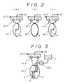
- the device for controlling an amount of removed water having the foregoing construction delivers the deaerated and fresh dialysate to the one room of the dosing chamber MCi at the fluid supply side by means of path of the changeover valve SVi by the degassing device DG, and the diaphragm 4 that partitions the room is expanded and shifted to fill at its full capacity (refer to Fig. 2).
- the diaphragm 4 constructed such that it extends from the one to the other of the inner walls and when the incoming dialysate fills the one room of the dosing chamber MCi and the flow stops at that moment, the pressure of the pipeline at the inflow side sharply rises.
- the pressure rising phenomenon can be detected by the pressure detector PSi, and the changeover valve SVi can be operated by the signal.
- the changeover valve SVi When the changeover valve SVi is operated, the dialysate flows into the opposite room of the dosing chamber MCi, and the pressure of the circuit 2 at the dialysate supply side which is detected by the pressure detector PSi returns to the original level.
- the operation ranging from the detection of the fill of the one room to the change of the inflow path is an instant operation, and the fluid paths of both of the separated rooms can be simultaneously changed by the changeover valve SVi, and the one room to which the fluid flowed in before the changeover sends the fresh dialysate to the circuit of the dialyzer DL by reversing of the path. Also, the waste fluid passing through the dialyzer DL is led to the dosing chamber MCo of a volume equal to that of the dosing chamber MCi, and the operation is taken place with the inflow of the waste fluid and the drain thereof alternately to the left and right rooms, and the fluid is sucked out by the suction pump PU.
- the liquid of non-volatile type (silicone oil, paraffin oil and the like) without bubbles or solvent gas is filled at its full capacity, and the communication between the fluid reservoir 7 and the central chamber 6 is closed by closing the volume adjusting valve SVm, and the volume in the central chamber 6 is made adjustable to control the volume of the dosing chamber MCo.
- the pressure signals of inflow into the left and right rooms and filling are detected by the pressure detector PSo equipped between the dosing chamber MCo and the suction pump PU and the scaling is obtained by operating the changeover valve SVo.
- the function of hemodialysis is to eliminate the waste which is the uremic material from the blood, and its object is to provide the treatment of diffusion by the difference in the concentrations with the dialysate and perform an elimination of water, and the foregoing paragraph may be determined by the properties of the dialyzer, but the elimination of water content is physically performed by the pressure difference between the blood and the dialysate by means of the film of the dialyzer.
Landscapes
- Health & Medical Sciences (AREA)
- Heart & Thoracic Surgery (AREA)
- Urology & Nephrology (AREA)
- Hematology (AREA)
- Vascular Medicine (AREA)
- Engineering & Computer Science (AREA)
- Anesthesiology (AREA)
- Biomedical Technology (AREA)
- Emergency Medicine (AREA)
- Life Sciences & Earth Sciences (AREA)
- Animal Behavior & Ethology (AREA)
- General Health & Medical Sciences (AREA)
- Public Health (AREA)
- Veterinary Medicine (AREA)
- External Artificial Organs (AREA)
- Separation Using Semi-Permeable Membranes (AREA)
Claims (5)
- Vorrichtung zum Regeln eines Wasserentzugs, der bei einer Hämodialyse mit einem Dialysator (DL) anfällt, wobei der Dialysator Flüssigkeitsdosierkammern (MCi, MCo) aufweist, und jede Kammer über eine Membran in zwei Räume aufgeteilt ist, dadurch gekennzeichnet, daß- die Flüssigkeitsdosierkammern unabhängig in einer Flüssigkeitszuströmseite und einer Flüssigkeitsabströmseite eines Dialysekreislaufs angeordnet sind, daß ein jeder Raum über Umkehrventile (SVi, SVo) reversibel mit einer Einlaßseite oder einer Auslaßseite der Dosierkammern (MCi, MCo) verbunden ist,- auf der Abströmseite der Dosierkammer (MCo) eine Saugpumpe (PU) vorgesehen ist, daß drei Elektromagnetventile (Vi, Vo, VB) zur Unterbrechung der Verbindung mit dem Dialysator (DL) und zur Bildung einer Bypaßleitung vorgesehen sind, daß eine zentrale Regelungseinheit (CPU) zur Regelung des Antriebs der Saugpumpe (PU) und der Umkehrventile (SVi, SVo) auf der Grundlage der Wechselbeziehung von Eingabeinformationen von an eine Leitung der Flüssigkeitszuztrömseite und der Flüssigkeitsabströmseite der Vorrichtung angeordneten Drucksensoren (PSi, PSo) vorgesehen ist, wobei in wenigstens einer der auf der Flüssigkeitszuströmseite oder der Flüssigkeitsabströmseite der Vorrichtung angeordneten Flüssigkeitsdosierkammern (MCo) zwei Membranen (5, 5') vorgesehen sind, und die beiden Membranen (5, 5') zwischen sich eine zentrale Kammer (6) bilden, deren Volumen über ein Volumeneinstellmittel, z.B. ein Volumeneinstellventil (SVm), einstellbar ist.
- Vorrichtung nach Anspruch 1, dadurch gekennzeichnet, daß in Strömungsrichtung vor dem Drucksensor (PSi) eine Entgasungsvorrichtung (DG) mit einem Blasendetektor (AD) vorgesehen ist.
- Verfahren zur Regelung eines Wasserentzugs, der bei einer Hämodialyse mit einem Dialysator (DL) erhalten wird unter Verwendung einer Vorrichtung gemäß der Ansprüche 1 oder 2, gekennzeichnet durch- Umkehrung der Umkehrventile (SVo, SVi) am Auslaß und Einlaß der Flüssigkeitsdosierkammern (MCi, MCo), die unabhängig auf der Flüssigkeitszuströmseite und der Flüssigkeitsabströmseite der Vorrichtung vorgesehen sind, mittels Ansteuerung durch die zentrale Regelungseinheit (CPU) auf der Grundlage von Eingabeinformationen von den Drucksensoren (PSo, PSi),- Berechnen eines Differenzwertes aus von den Drucksensoren (PSo, PSi) erhaltenen Signalen durch die zentrale Regelungseinheit (CPU),- Bedienung der Umkehrventile (SVo, SVi), wenn der Wert sich in einem festen Bereich befindet,- Berechnung einer Periodendauerdifferenz auf der Flüssigkeitszuströmseite und der Flüssigkeitsabstörmseite durch Erfassen der Periodendauer eines jeden Umkehrventils (SVo, SVi),- Berechnung eines Wasserentzugs auf der Grundlage der Periodendauerdifferenz, und- Regelung der Flüssigkeitsströmung der Saugpumpe (PU), so daß sie einer gewünschten Menge entspricht.
- Verfahren nach Anspruch 3, gekennzeichnet durch Erfassen und Umkehrung der Periodendauer der Umkehrventile (SVi, SVo) in einem Zustand, in dem das elektromagnetische Ventil (VB) des Bypasses periodisch geöffnet ist und die elektromagnetischen Ventile (Vi, Vo) geschlossen sind, um die Verbindung zum Dialysator (DL) zu unterbrechen, und durch Korrigieren des Fehlers der Volumendifferenz der Dosierkammern durch Berechnung des Kompensationswerts, der durch eine Volumenänderung bei der Expansion der Meßeinheit durch Temperatur oder mechanischen Verschleiß oder Abrieb hervorgerufen wird.
- Verfahren nach Anspruch 4, gekennzeichnet durch- Auffüllen einer der Räume der Dosierkammer (MCi, MCo) bis beide Räume mit Flüssigkeit angefüllt sind und die Drucksensoren (PSi, PSo) eine Druckänderung feststellen,- Aktivierung der Umkehrventile (SVi, SVo) zur Umkehrung der Strömung in die Dosierkammer (MCi, MCo),- Auffüllen des anderen Raums der Dosierkammern (MCi, MCo) bis einer oder beide Räume mit Fluid angefüllt sind und die Drucksensoren (PSi, PSo) eine Druckänderung feststellen,- Berechnung der Volumendifferenz der beiden Dosierkammern (MCi, MCo) aus einer Zeitdifferenz zwischen den erfaßten Druckänderungen der beiden Drucksensoren (PSi, PSo) durch Verwendung einer zentralen Regelungseinheit (CPU),- Öffnung des Volumeneinstellventils (SVm) für eine Periodendauer, die von der berechneten Zeitdifferenz abhängt und- Erhöhen oder Verringern des Volumens einer zentralen Kammer (6) zwischen zwei Membranen (5, 5') der Dosierkammer (MCo) durch Zugabe von Fluid in die Kammer bzw. Entnahme von Fluid aus der Kammer.
Priority Applications (5)
| Application Number | Priority Date | Filing Date | Title |
|---|---|---|---|
| EP88105865A EP0336993B1 (de) | 1988-04-13 | 1988-04-13 | Methode zur Regelung des Wasserentzuges durch Ultrafiltration und Regelungsvorrichtung zur Regelung als Wasserentzugs durch Ultrafiltration während der Hämodialyse |
| DE88105865T DE3882519T2 (de) | 1988-04-13 | 1988-04-13 | Methode zur Regelung des Wasserentzuges durch Ultrafiltration und Regelungsvorrichtung zur Regelung als Wasserentzugs durch Ultrafiltration während der Hämodialyse. |
| ES198888105865T ES2040773T3 (es) | 1988-04-13 | 1988-04-13 | Metodo de control de la cantidad de agua extraida por ultrafiltracion, y dispositivo de control de la cantidad de agua extraida por ultrafiltracion en hemodialisis. |
| US07/180,952 US4971700A (en) | 1988-04-13 | 1988-04-13 | Method of controlling amount of removed water by ultrafiltration and control device for controlling amount of removed water by ultrafiltration in hemodialysis |
| US07/531,767 US5009775A (en) | 1988-04-13 | 1990-06-01 | Method of controlling amount of removed water by ultrafiltration and control device for controlling amount of removed water by ultrafiltration in hemodialysis |
Applications Claiming Priority (1)
| Application Number | Priority Date | Filing Date | Title |
|---|---|---|---|
| EP88105865A EP0336993B1 (de) | 1988-04-13 | 1988-04-13 | Methode zur Regelung des Wasserentzuges durch Ultrafiltration und Regelungsvorrichtung zur Regelung als Wasserentzugs durch Ultrafiltration während der Hämodialyse |
Publications (2)
| Publication Number | Publication Date |
|---|---|
| EP0336993A1 EP0336993A1 (de) | 1989-10-18 |
| EP0336993B1 true EP0336993B1 (de) | 1993-07-21 |
Family
ID=8198884
Family Applications (1)
| Application Number | Title | Priority Date | Filing Date |
|---|---|---|---|
| EP88105865A Expired - Lifetime EP0336993B1 (de) | 1988-04-13 | 1988-04-13 | Methode zur Regelung des Wasserentzuges durch Ultrafiltration und Regelungsvorrichtung zur Regelung als Wasserentzugs durch Ultrafiltration während der Hämodialyse |
Country Status (4)
| Country | Link |
|---|---|
| US (1) | US4971700A (de) |
| EP (1) | EP0336993B1 (de) |
| DE (1) | DE3882519T2 (de) |
| ES (1) | ES2040773T3 (de) |
Families Citing this family (37)
| Publication number | Priority date | Publication date | Assignee | Title |
|---|---|---|---|---|
| US5486286A (en) | 1991-04-19 | 1996-01-23 | Althin Medical, Inc. | Apparatus for performing a self-test of kidney dialysis membrane |
| DE4308586C1 (de) * | 1993-03-18 | 1994-05-11 | Fresenius Ag | Hämodialysegerät mit einer Bilanzkammer |
| US5709670A (en) * | 1994-05-03 | 1998-01-20 | Aquintel, Inc. | Surgical fluid and tissue loss monitor |
| US6877713B1 (en) | 1999-07-20 | 2005-04-12 | Deka Products Limited Partnership | Tube occluder and method for occluding collapsible tubes |
| US7241272B2 (en) | 2001-11-13 | 2007-07-10 | Baxter International Inc. | Method and composition for removing uremic toxins in dialysis processes |
| WO2003086509A1 (en) | 2002-04-11 | 2003-10-23 | Deka Products Limited Partnership | System and method for delivering a target volume of fluid |
| WO2004009158A2 (en) | 2002-07-19 | 2004-01-29 | Baxter International Inc. | Systems and methods for performing peritoneal dialysis |
| US8029454B2 (en) | 2003-11-05 | 2011-10-04 | Baxter International Inc. | High convection home hemodialysis/hemofiltration and sorbent system |
| CA2970214C (en) | 2006-04-14 | 2021-08-17 | Deka Products Limited Partnership | System for pumping a biological fluid |
| US10537671B2 (en) | 2006-04-14 | 2020-01-21 | Deka Products Limited Partnership | Automated control mechanisms in a hemodialysis apparatus |
| US8042563B2 (en) | 2007-02-27 | 2011-10-25 | Deka Products Limited Partnership | Cassette system integrated apparatus |
| US8491184B2 (en) | 2007-02-27 | 2013-07-23 | Deka Products Limited Partnership | Sensor apparatus systems, devices and methods |
| US8562834B2 (en) | 2007-02-27 | 2013-10-22 | Deka Products Limited Partnership | Modular assembly for a portable hemodialysis system |
| US10463774B2 (en) | 2007-02-27 | 2019-11-05 | Deka Products Limited Partnership | Control systems and methods for blood or fluid handling medical devices |
| US8888470B2 (en) | 2007-02-27 | 2014-11-18 | Deka Products Limited Partnership | Pumping cassette |
| US8409441B2 (en) | 2007-02-27 | 2013-04-02 | Deka Products Limited Partnership | Blood treatment systems and methods |
| US9028691B2 (en) | 2007-02-27 | 2015-05-12 | Deka Products Limited Partnership | Blood circuit assembly for a hemodialysis system |
| US8357298B2 (en) | 2007-02-27 | 2013-01-22 | Deka Products Limited Partnership | Hemodialysis systems and methods |
| US8425471B2 (en) | 2007-02-27 | 2013-04-23 | Deka Products Limited Partnership | Reagent supply for a hemodialysis system |
| US20090107335A1 (en) | 2007-02-27 | 2009-04-30 | Deka Products Limited Partnership | Air trap for a medical infusion device |
| MX357266B (es) | 2007-02-27 | 2018-07-03 | Deka Products Lp | Sistemas y metodos de hemodialisis. |
| US8393690B2 (en) | 2007-02-27 | 2013-03-12 | Deka Products Limited Partnership | Enclosure for a portable hemodialysis system |
| US8114276B2 (en) | 2007-10-24 | 2012-02-14 | Baxter International Inc. | Personal hemodialysis system |
| US9415150B2 (en) | 2007-11-09 | 2016-08-16 | Baxter Healthcare S.A. | Balanced flow dialysis machine |
| US10201647B2 (en) | 2008-01-23 | 2019-02-12 | Deka Products Limited Partnership | Medical treatment system and methods using a plurality of fluid lines |
| US10195330B2 (en) | 2008-01-23 | 2019-02-05 | Deka Products Limited Partnership | Medical treatment system and methods using a plurality of fluid lines |
| EP3100750B1 (de) | 2008-01-23 | 2020-06-10 | DEKA Products Limited Partnership | Pumpenkassette zur verwendung in medizinischen behandlungssystemen mit mehreren flüssigkeitsleitungen |
| ES2573483T3 (es) * | 2008-04-15 | 2016-06-08 | Gambro Lundia Ab | Aparato y método de tratamiento de la sangre |
| US12171922B2 (en) | 2008-08-27 | 2024-12-24 | Deka Products Limited Partnership | Blood treatment systems and methods |
| CN104841030B (zh) | 2009-10-30 | 2017-10-31 | 德卡产品有限公司 | 用于检测血管内接入装置的断开的装置和方法 |
| US8322091B2 (en) * | 2010-02-09 | 2012-12-04 | Atwood Mobile Products, Llc | Window frame assembly with integral seals |
| JP6239501B2 (ja) | 2011-05-24 | 2017-11-29 | デカ・プロダクツ・リミテッド・パートナーシップ | 血液処置システムおよび方法 |
| US9999717B2 (en) | 2011-05-24 | 2018-06-19 | Deka Products Limited Partnership | Systems and methods for detecting vascular access disconnection |
| EP4074351A1 (de) | 2011-05-24 | 2022-10-19 | DEKA Products Limited Partnership | Hämodialysesystem |
| EP3498316B1 (de) | 2011-11-04 | 2020-07-22 | DEKA Products Limited Partnership | System und verfahren zur medizinischen behandlung unter verwendung einer vielzahl von flüssigkeitsleitungen |
| US12303631B2 (en) | 2011-11-04 | 2025-05-20 | Deka Products Limited Partnership | Medical treatment system and methods using a plurality of fluid lines |
| US12026271B2 (en) | 2014-05-27 | 2024-07-02 | Deka Products Limited Partnership | Control systems and methods for blood or fluid handling medical devices |
Family Cites Families (7)
| Publication number | Priority date | Publication date | Assignee | Title |
|---|---|---|---|---|
| US4037616A (en) * | 1975-06-27 | 1977-07-26 | Harry Pinkerton | Proportioning fluids |
| JPS5272379A (en) * | 1975-12-15 | 1977-06-16 | Toray Ind Inc | Separation of fluid |
| DE2838414C2 (de) * | 1978-09-02 | 1984-10-31 | Fresenius AG, 6380 Bad Homburg | Vorrichtung zur Hämodialyse und zum Entziehen von Ultrafiltrat |
| US4209391A (en) * | 1978-11-06 | 1980-06-24 | Cordis Dow Corp. | Apparatus and method for automatically controlling hemodialysis at a pre-selected ultrafiltration rate |
| US4366061A (en) * | 1980-01-23 | 1982-12-28 | Cordis Dow Corp. | Automated diaphragm apparatus and method for controlling negative pressure hemodialysis treatment |
| US4477342A (en) * | 1982-08-31 | 1984-10-16 | Becton, Dickinson And Company | Apparatus and method for controlling ultrafiltration during hemodialysis |
| DE3328744A1 (de) * | 1983-08-09 | 1985-02-28 | Fresenius AG, 6380 Bad Homburg | Haemodialysevorrichtung |
-
1988
- 1988-04-13 ES ES198888105865T patent/ES2040773T3/es not_active Expired - Lifetime
- 1988-04-13 EP EP88105865A patent/EP0336993B1/de not_active Expired - Lifetime
- 1988-04-13 DE DE88105865T patent/DE3882519T2/de not_active Expired - Fee Related
- 1988-04-13 US US07/180,952 patent/US4971700A/en not_active Expired - Fee Related
Also Published As
| Publication number | Publication date |
|---|---|
| ES2040773T3 (es) | 1993-11-01 |
| DE3882519T2 (de) | 1993-11-11 |
| US4971700A (en) | 1990-11-20 |
| EP0336993A1 (de) | 1989-10-18 |
| DE3882519D1 (de) | 1993-08-26 |
Similar Documents
| Publication | Publication Date | Title |
|---|---|---|
| EP0336993B1 (de) | Methode zur Regelung des Wasserentzuges durch Ultrafiltration und Regelungsvorrichtung zur Regelung als Wasserentzugs durch Ultrafiltration während der Hämodialyse | |
| US5522998A (en) | Hemodialysis apparatus having a single balance chamber and method of dialyzing blood therewith | |
| US6042784A (en) | Method and apparatus for ultrafiltration in hemodialysis | |
| EP1424089B1 (de) | Dialysemaschine | |
| US4769134A (en) | Open patient fluid management method and system | |
| EP0306241B1 (de) | Dialysesystem | |
| SE444116B (sv) | Anordning for automatisk styrning av hemodialys | |
| US3990973A (en) | Apparatus for measuring ultrafiltration rate | |
| US4093545A (en) | Method and apparatus for determining the amount of ultrafiltration during dialysis | |
| GB2032136A (en) | Hemodialysis apparatus | |
| US4334988A (en) | Control of dialysis and ultrafiltration | |
| CN111630362A (zh) | 压力检测器的调整装置 | |
| US5009775A (en) | Method of controlling amount of removed water by ultrafiltration and control device for controlling amount of removed water by ultrafiltration in hemodialysis | |
| CN106061524A (zh) | 用于在从医学的处理装置中的流出和流入之间进行平衡的装置和方法 | |
| CA1315702C (en) | Method of controlling amount of removed water by ultrafiltration and control device for controlling amount of removed water by ultrafiltration in hemodialysis | |
| JP4635284B2 (ja) | 吸排ポンプ | |
| KR940002244B1 (ko) | 혈액 투석에 있어서의 제수량 제어방법 및 제어장치 | |
| JP3187938B2 (ja) | 血液透析装置 | |
| EP1342479B1 (de) | Einrichtung zur Kontrolle und Regulierung des Dialysatflusses in einem Hämodiafiltrationsverfahren | |
| JPS62155859A (ja) | 血液透析装置における限外濾過量制御装置 | |
| CN2922917Y (zh) | 血液透析机的容量超滤控制系统 | |
| JPH01238870A (ja) | 血液透析における除水量制御装置 | |
| GB1560660A (en) | Dialyser system and control unit therefor | |
| JP2769514B2 (ja) | 血液透析装置の除水量制御装置 | |
| JP2544897B2 (ja) | 透析装置における限外濾過圧算出方法 |
Legal Events
| Date | Code | Title | Description |
|---|---|---|---|
| PUAI | Public reference made under article 153(3) epc to a published international application that has entered the european phase |
Free format text: ORIGINAL CODE: 0009012 |
|
| AK | Designated contracting states |
Kind code of ref document: A1 Designated state(s): AT BE CH DE ES FR GB GR IT LI LU NL SE |
|
| RBV | Designated contracting states (corrected) |
Designated state(s): DE FR GB IT SE |
|
| 17P | Request for examination filed |
Effective date: 19900314 |
|
| 17Q | First examination report despatched |
Effective date: 19911126 |
|
| GRAA | (expected) grant |
Free format text: ORIGINAL CODE: 0009210 |
|
| AK | Designated contracting states |
Kind code of ref document: B1 Designated state(s): DE ES FR GB IT SE |
|
| PG25 | Lapsed in a contracting state [announced via postgrant information from national office to epo] |
Ref country code: SE Effective date: 19930721 |
|
| REF | Corresponds to: |
Ref document number: 3882519 Country of ref document: DE Date of ref document: 19930826 |
|
| ITF | It: translation for a ep patent filed | ||
| ET | Fr: translation filed | ||
| REG | Reference to a national code |
Ref country code: ES Ref legal event code: FG2A Ref document number: 2040773 Country of ref document: ES Kind code of ref document: T3 |
|
| PG25 | Lapsed in a contracting state [announced via postgrant information from national office to epo] |
Ref country code: GB Effective date: 19940413 |
|
| PLBE | No opposition filed within time limit |
Free format text: ORIGINAL CODE: 0009261 |
|
| STAA | Information on the status of an ep patent application or granted ep patent |
Free format text: STATUS: NO OPPOSITION FILED WITHIN TIME LIMIT |
|
| 26N | No opposition filed | ||
| GBPC | Gb: european patent ceased through non-payment of renewal fee |
Effective date: 19940413 |
|
| PGFP | Annual fee paid to national office [announced via postgrant information from national office to epo] |
Ref country code: FR Payment date: 19950413 Year of fee payment: 8 |
|
| PGFP | Annual fee paid to national office [announced via postgrant information from national office to epo] |
Ref country code: ES Payment date: 19950428 Year of fee payment: 8 |
|
| PGFP | Annual fee paid to national office [announced via postgrant information from national office to epo] |
Ref country code: DE Payment date: 19950623 Year of fee payment: 8 |
|
| PG25 | Lapsed in a contracting state [announced via postgrant information from national office to epo] |
Ref country code: ES Free format text: LAPSE BECAUSE OF NON-PAYMENT OF DUE FEES Effective date: 19960415 |
|
| PG25 | Lapsed in a contracting state [announced via postgrant information from national office to epo] |
Ref country code: FR Effective date: 19961227 |
|
| PG25 | Lapsed in a contracting state [announced via postgrant information from national office to epo] |
Ref country code: DE Effective date: 19970101 |
|
| REG | Reference to a national code |
Ref country code: FR Ref legal event code: ST |
|
| REG | Reference to a national code |
Ref country code: ES Ref legal event code: FD2A Effective date: 19990201 |
|
| PG25 | Lapsed in a contracting state [announced via postgrant information from national office to epo] |
Ref country code: IT Free format text: LAPSE BECAUSE OF NON-PAYMENT OF DUE FEES;WARNING: LAPSES OF ITALIAN PATENTS WITH EFFECTIVE DATE BEFORE 2007 MAY HAVE OCCURRED AT ANY TIME BEFORE 2007. THE CORRECT EFFECTIVE DATE MAY BE DIFFERENT FROM THE ONE RECORDED. Effective date: 20050413 |