EP0336312A2 - Computergesteuerte universale Schleifmaschine und Verfahren zum Schleifen von hypo-, epitrochoidischen und kreisförmigen Laufbahnen - Google Patents
Computergesteuerte universale Schleifmaschine und Verfahren zum Schleifen von hypo-, epitrochoidischen und kreisförmigen Laufbahnen Download PDFInfo
- Publication number
- EP0336312A2 EP0336312A2 EP89105689A EP89105689A EP0336312A2 EP 0336312 A2 EP0336312 A2 EP 0336312A2 EP 89105689 A EP89105689 A EP 89105689A EP 89105689 A EP89105689 A EP 89105689A EP 0336312 A2 EP0336312 A2 EP 0336312A2
- Authority
- EP
- European Patent Office
- Prior art keywords
- grinding
- hypotrochoidal
- epitrochoidal
- rollers
- bearing race
- Prior art date
- Legal status (The legal status is an assumption and is not a legal conclusion. Google has not performed a legal analysis and makes no representation as to the accuracy of the status listed.)
- Withdrawn
Links
Images


Classifications
-
- B—PERFORMING OPERATIONS; TRANSPORTING
- B24—GRINDING; POLISHING
- B24B—MACHINES, DEVICES, OR PROCESSES FOR GRINDING OR POLISHING; DRESSING OR CONDITIONING OF ABRADING SURFACES; FEEDING OF GRINDING, POLISHING, OR LAPPING AGENTS
- B24B19/00—Single-purpose machines or devices for particular grinding operations not covered by any other main group
- B24B19/02—Single-purpose machines or devices for particular grinding operations not covered by any other main group for grinding grooves, e.g. on shafts, in casings, in tubes, homokinetic joint elements
- B24B19/06—Single-purpose machines or devices for particular grinding operations not covered by any other main group for grinding grooves, e.g. on shafts, in casings, in tubes, homokinetic joint elements for grinding races, e.g. roller races
Definitions
- This invention relates to machines for making parts in which two or more parts have shaped surfaces that must bear a precision relationship. More particularly this invention relates to machines for making parts having both trochoidal and circular surfaces that must be positioned in precision relationship to each other. Such machines are useful in speed change devices and other units having a plurality of shaped surfaces which must have a near perfect eccentricity between all of the shaped surfaces.
- Speed change devices having both hypotrochoidal and epitrochoidal surfaces that must bear predetermined precision positions in relation to each other and to circular bearing races are described in U.S. Patents 4,584,904 to Distin and Shaffer and 4,643,047 to to Distin.
- the speed change devices described in those patents make use of rollers positioned between adjacent epitrochoidal and hypotrochoidal bearing races to reduce friction and backlash. Grinding machines for making such parts typically are capable of grinding only one surface without making a new set-up. In speed change devices made by such a method it is difficult or impossible to maintain the degree of concentricity necessary for optimum operation.
- the grinding machine is constructed to shape three basic parts useful in the speed change devices set forth in the above-referenced patents: (a) an orbital inner element or rotor having an epitrochoidal surface (called the "EPI Orbiting Rotor”); (b) a reaction ring having a hypotrochoidal surface (called the “HYPO Reacting Ring”); and (c) an output ring having a hypotrochoidal surface (called the "HYPO Output Ring”).
- the first part has two concentric outer circular epitrochoidal races and an inner circular bearing race that is concentric with the two epitrochoidal surfaces.
- the second part has an inner hypotrochoidal bearing race, an inner circular bearing race and an outer pilot diameter, all of which must be concentric.
- the last part has an inner hypotrochoidal bearing race, an outer circular bearing race and an inner circular bearing race, all of which must be concentric.
- a servomotorized table is arranged to be driven at any selected rotary speed.
- a second rotary table is mounted on top of first table and is capable of lateral adjustment to provide any desired degree of eccentricity between the rotation centers of the tables.
- the upper table is driven by a second servomotor so that its speed, relative to the lower table, can be adjusted to any desired speed and in either direction.
- Three independently controlled grinding spindles, capable of horizontal and vertical adjustment, perform the successive drilling operations.
- the true trochoidal contours of the bearing races are generated analogously with high precision under computer control with minimal software.
- the true contours can be ground as rapidly as if they were circular.
- the grinder can accommodate epitrochoidal and hypotrochoidal rings with different pitch diameters and with different numbers of intervening rollers.
- the machine is completely automatic through the complete grinding cycle and switches from epitrochoidal and hypotrochoidal contour to circular without operator intervention and without any change in the machine setup.
- a base 1 supports an upper structure 2 that carries a horizontally-adjustable slide support 3.
- Three vertically-adjustable slide supports 4, 5 and 6 are rigidly mounted in spaced positions on the support 3.
- Three grinding support brackets 7, 8 and 9 are respectively mounted for vertical movement on the slide supports 4, 5 and 6. These brackets 7, 8 and 9 in turn respectively carry three motorized grinding spindles 10, 11, and 12.
- the horizontal position of the horizontally-slideable support 3 is controlled by a lead screw driven by a servomotor 13.
- the vertical positions of the brackets 7, 8 and 9 are controlled respectively by means of lead screws operated by servomotors 14, 15 and 16.
- a rotary table 17 is mounted on the base 1 and is operated by a servomotor adjustable to any desired speed and direction of rotation.
- An upper rotary table 18 is mounted on the table 17 and is driven by a separate servomotor by which its speed and direction of rotation can be adjusted relative to the speed and direction of rotation of the table 17.
- the axis of rotation of the table 18, when in its zero-reference position, is concentric with the axis of rotation of the lower table 17.
- the table 18, however, is adjustable horizontally with respect to the table 17. By this means, the table 18 can be adjusted to provide the desired degree of eccentricity and then locked in that position.
- Known mechanisms can be used to provide the rotary and offset movements of the tables 17 and 18.
- the table 17 can be provided with a rotatable platen 17a, controlled by a servo motor (not shown) mounted within the table 17.
- the upper table 18, is supported on the platen 17a and is slideable horizontally with respect to the table 17.
- the table 18 carries a rotatable platen 18a that is driven by a servo motor (not shown) positioned within the table 18.
- Any other construction that provides two independently controllable mounting tables can be used.
- the tables 17 and 18 will be referred to as the mounting elements and the motions ascribed to them may in fact be the motions of the associated platens 17a and 18a.
- the rotation of the servomotors 13, 14, 15, and 16 and the speed of the servomotorized tables 17 and 18 are each controlled, in known fashion, by a computer (not shown).
- the lower end of each of the spindles 10, 11 and 12 carries a grinding wheel selected in accordance with the particular grinding function.
- the part to be formed in this case the EPI Orbiting Ring shown in Figure 2, previously rough machined to the approximate size and shape of the finished part, is mounted on a magnetic chuck 19, secured tothe top of table 18, in a position concentric with the rotation of the table 18.
- the trochoidal bearing races are always operated in conjugate sets of two, consisting of the outer epitrochoidal bearing race and the inner hypotrochoidal bearing race, as illustrated by Figure 1.
- a set of rollers 38 is interposed between the inner and outer bearing races and are more fully described in the above-referenced patents.
- the trochoidal bearing races are defined by two basic parameters: (a) the number of rollers 38, and (b) the pitch diameter of the rollers 38.
- the pitch diameter of the rollers is selected according to the torque to be transmitted.
- the maximum size of the roller diameter is established and the maximum eccentricity is also established so there will be minimum clearance between the lobes of the epitrochoidal race and its associated hypotrochoidal race. This clearance is typically between 0.005 and 0.010 inches.
- the number of lobes on the hypotrochoidal race is always N + 1; the number of lobes on the epitrochoidal race is always N - 1; the theoretical major diameter of the epitrochoidal race is equal to D - d + e; the theoretical minor diameter of the epitrochoidal race is equal to D - d -e; the theoretical major diameter of the hypotrochoidal race is equal to D + d + e; and the theoretical minor diameter of the hypotrochoidal race is equal to D + d - e; where "D” is the pitch diameter of the rollers 38, “d” equals the roller diameter; and “e” equals the eccentricity which is equal to the radius of the orbital path of the inner element.
- Locating pins 29 and 30 are located in the magnetic clutch 19. These pins are of different diameters and are uniquely located to correctly position and orient the blank radially and angularly for grinding.
- a grinding wheel with a diameter equal or nearly equal to that of the rollers used on the epitrochoidal race 21 is then mounted on the spindle 22.
- a grinding wheel with a diameter equal to that of the rollers to be used on the epitrochoidal bearing race 20 is mounted on the spindle 11.
- a cylindrical cup-type grinding wheel with a diameter less than the diameter of the bearing race 22 is mounted on the spindle 10.
- the rotary table is displaced horizontally from its zero-reference position by a distance equal to one half the eccentricity (e/2) and clamped in place.
- the computer is then programmed, in known manner, so the two rotary tables 17 and 18 are synchronized as follows:
- the upper rotary table 18 will rotate in the opposite direction at a speed equal to that of the rotary table 17 minus 1/(N-1) turn, where N is the number of rollers.
- the speed ratio between rotary tables 17 and 18 is then equal to 1- (1/(N-1) with the two table always rotating in opposite directions.
- the operating cycle is as follows:
- the finished part is then removed from the magnetic chuck 19 and each of the grinding spindles is retracted.
- the two rotary tables 17 and 18 are each returned to the home position.
- the machine is then ready to process another EPI Orbiting Rotor.
- the grinding machine is prepared as follows:
- the two rotary tables 17 and 18 are synchronously programmed so that for each turn of the bottom table 17, the upper rotary table 18 will rotate in the opposite direction one turn plus 1/(N+1) turn, where N is the number of rollers.
- the speed ratio between between the tables 17 and 18 is then equal to 1 + [1/(N+1)], with the two tables always turning in opposite directions.
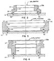
- the spindle 12 is fitted with a grinding wheel having a diameter equal oe nearly equal to that of the roller to be used on the hypotrochoidal bearing race 23.
- the spindle 11 is fitted with a form grinding wheel to grind the bearing race 24.
- the spindle 10 is fitted with a cup-type cylindrical grinding wheel to grind the pilot diameter 23.
- the grinding cycle of the machine is as follows:
- the machine will be prepared as follows: The eccentricity of the two rotary tables is not changed, but the synchronization is modified according to the new number of rollers with the ratio being equal to 1 + [1/(N+1)], where N is the number of rollers.
- the spindle 12 is fitted with a grinding wheel having a diameter equal or nearly equal to that of the rollers to be used on the hypotrochoidal bearing race 26.
- the spindle 11 is fitted with a cup-type cylindrical grinding wheel with a diameter smaller than the diameter of the bearing race 28.
- the spindle 10 is fitted with the same form grinding wheel as was used to grind the bearing race 24 of the HYPO Reacting Rind 23a.
- the grinding cycle is as follows:
Landscapes
- Engineering & Computer Science (AREA)
- Mechanical Engineering (AREA)
- Grinding Of Cylindrical And Plane Surfaces (AREA)
- Grinding And Polishing Of Tertiary Curved Surfaces And Surfaces With Complex Shapes (AREA)
Applications Claiming Priority (2)
| Application Number | Priority Date | Filing Date | Title |
|---|---|---|---|
| US17684688A | 1988-04-04 | 1988-04-04 | |
| US176846 | 1988-04-04 |
Publications (2)
| Publication Number | Publication Date |
|---|---|
| EP0336312A2 true EP0336312A2 (de) | 1989-10-11 |
| EP0336312A3 EP0336312A3 (de) | 1991-01-09 |
Family
ID=22646100
Family Applications (1)
| Application Number | Title | Priority Date | Filing Date |
|---|---|---|---|
| EP19890105689 Withdrawn EP0336312A3 (de) | 1988-04-04 | 1989-03-31 | Computergesteuerte universale Schleifmaschine und Verfahren zum Schleifen von hypo-, epitrochoidischen und kreisförmigen Laufbahnen |
Country Status (2)
| Country | Link |
|---|---|
| EP (1) | EP0336312A3 (de) |
| JP (1) | JPH0288163A (de) |
Cited By (2)
| Publication number | Priority date | Publication date | Assignee | Title |
|---|---|---|---|---|
| DE102015215624A1 (de) * | 2015-08-17 | 2017-02-23 | Schaeffler Technologies AG & Co. KG | Verfahren zur Herstellung von Lagerkomponenten mittels einer Fertigungsstraße, Fertigungsstraße und Fertigungsanlage |
| GB2579784A (en) * | 2018-12-13 | 2020-07-08 | Rolls Royce Plc | Manufacturing method |
Family Cites Families (11)
| Publication number | Priority date | Publication date | Assignee | Title |
|---|---|---|---|---|
| GB278203A (en) * | 1926-11-15 | 1927-10-06 | Lorenz Konrad Braren | Improvements in or relating to production of cycloidal curves |
| US2151483A (en) * | 1935-06-05 | 1939-03-21 | Arthur A Nichols | Rotor generating method and machine |
| FR1531602A (fr) * | 1967-05-18 | 1968-07-05 | Appareil pour tailler et diviser des formes elliptiques ou autres formes curvilignescirconscrites à un cercle | |
| JPS48109573U (de) * | 1972-03-21 | 1973-12-17 | ||
| JPS5646949B2 (de) * | 1973-09-28 | 1981-11-06 | ||
| DE2544666C3 (de) * | 1975-10-06 | 1979-11-08 | Gebrueder Grieshaber, Metallwarenfabrik, 7620 Wolfach | Schleifmaschine für die Feinstbearbeitung von kugelförmigen Innenflächen |
| JPS5657411A (en) * | 1979-10-18 | 1981-05-19 | Ikeda Bussan Co | Seat having changeable contact surface |
| JPS5871062A (ja) * | 1981-10-24 | 1983-04-27 | Ntn Toyo Bearing Co Ltd | 円錐ころ軸受内輪の加工方法 |
| JPS6234765A (ja) * | 1985-08-06 | 1987-02-14 | Mazda Motor Corp | 非真円形状加工物の加工方法 |
| JPS62136352A (ja) * | 1985-12-06 | 1987-06-19 | Amada Co Ltd | 軸受案内面加工方法 |
| JPS62188662A (ja) * | 1987-02-06 | 1987-08-18 | Bandou Kiko Kk | 数値制御によるガラス板の研削方法 |
-
1989
- 1989-03-31 EP EP19890105689 patent/EP0336312A3/de not_active Withdrawn
- 1989-04-04 JP JP8563889A patent/JPH0288163A/ja active Pending
Cited By (5)
| Publication number | Priority date | Publication date | Assignee | Title |
|---|---|---|---|---|
| DE102015215624A1 (de) * | 2015-08-17 | 2017-02-23 | Schaeffler Technologies AG & Co. KG | Verfahren zur Herstellung von Lagerkomponenten mittels einer Fertigungsstraße, Fertigungsstraße und Fertigungsanlage |
| US10695885B2 (en) | 2015-08-17 | 2020-06-30 | Schaeffler Technologies AG & Co. KG | Method for producing bearing components by means of a production line, production line and production system |
| GB2579784A (en) * | 2018-12-13 | 2020-07-08 | Rolls Royce Plc | Manufacturing method |
| GB2579784B (en) * | 2018-12-13 | 2021-05-05 | Rolls Royce Plc | Component manufacturing using a grinding tool following a trochoidal path |
| US11267096B2 (en) | 2018-12-13 | 2022-03-08 | Rolls-Royce Plc | Manufacturing method |
Also Published As
| Publication number | Publication date |
|---|---|
| EP0336312A3 (de) | 1991-01-09 |
| JPH0288163A (ja) | 1990-03-28 |
Similar Documents
| Publication | Publication Date | Title |
|---|---|---|
| RU2212315C2 (ru) | Способ и станок механической обработки предварительно обработанных зубчатых заготовок, например шестерней | |
| US4090422A (en) | Tool machine for machining crank shafts | |
| US4339895A (en) | Method of grinding gear teeth flanks | |
| US4052928A (en) | Cam-type gearing and the like | |
| US5975995A (en) | Machining apparatus and method | |
| US5472368A (en) | Method of and machine for grinding cams | |
| US3757474A (en) | Curved surface generator | |
| US4768904A (en) | Apparatus for broaching cylindrical surfaces of a workpiece, in particular of a crankshaft | |
| US4891914A (en) | Computer controlled universal grinder and method for grinding trochoidal and circular bearing races | |
| US4494280A (en) | Method and machine tool for a circular machining of eccentric shaft portions | |
| US3750345A (en) | Machine tool | |
| EP0336312A2 (de) | Computergesteuerte universale Schleifmaschine und Verfahren zum Schleifen von hypo-, epitrochoidischen und kreisförmigen Laufbahnen | |
| EP0423146B1 (de) | Schleifen von werkstücken | |
| EP1635975A1 (de) | Gerät für die umlaufbahnartige bearbeitung mit antriebselement mit antriebsstiften | |
| US4918862A (en) | Method for grinding trochoidal and circular bearing races | |
| US3964367A (en) | Device for machining trochoidal inner walls, especially for the cylinders of Wankel engines | |
| JP2000108029A (ja) | 研削盤 | |
| SU1116976A3 (ru) | Станок дл шлифовани торцевых поверхностей деталей | |
| CN213969320U (zh) | 一种旋转式滚沟机构 | |
| US3948144A (en) | Peritrochoid curved surface generating apparatus | |
| CN108481146A (zh) | 圆弧曲面加工机床 | |
| JP3815130B2 (ja) | センタレス研削方法およびセンタレス研削盤 | |
| JPS63278702A (ja) | 円筒面を精密旋削するための加工装置 | |
| GB2116463A (en) | Process and apparatus for grinding the surface of a cam | |
| SU1696193A1 (ru) | Роторный зубодолбежный станок |
Legal Events
| Date | Code | Title | Description |
|---|---|---|---|
| PUAI | Public reference made under article 153(3) epc to a published international application that has entered the european phase |
Free format text: ORIGINAL CODE: 0009012 |
|
| AK | Designated contracting states |
Kind code of ref document: A2 Designated state(s): CH DE FR GB IT LI NL |
|
| PUAL | Search report despatched |
Free format text: ORIGINAL CODE: 0009013 |
|
| AK | Designated contracting states |
Kind code of ref document: A3 Designated state(s): CH DE FR GB IT LI NL |
|
| STAA | Information on the status of an ep patent application or granted ep patent |
Free format text: STATUS: THE APPLICATION IS DEEMED TO BE WITHDRAWN |
|
| 18D | Application deemed to be withdrawn |
Effective date: 19910710 |