EP0335989A1 - Insoluble anode made of lead alloy - Google Patents
Insoluble anode made of lead alloy Download PDFInfo
- Publication number
- EP0335989A1 EP0335989A1 EP88105286A EP88105286A EP0335989A1 EP 0335989 A1 EP0335989 A1 EP 0335989A1 EP 88105286 A EP88105286 A EP 88105286A EP 88105286 A EP88105286 A EP 88105286A EP 0335989 A1 EP0335989 A1 EP 0335989A1
- Authority
- EP
- European Patent Office
- Prior art keywords
- anode
- lead
- insoluble anode
- weight
- alloy
- Prior art date
- Legal status (The legal status is an assumption and is not a legal conclusion. Google has not performed a legal analysis and makes no representation as to the accuracy of the status listed.)
- Granted
Links
- 229910000978 Pb alloy Inorganic materials 0.000 title claims description 17
- 229910045601 alloy Inorganic materials 0.000 claims abstract description 12
- 239000000956 alloy Substances 0.000 claims abstract description 12
- 238000007599 discharging Methods 0.000 claims abstract description 8
- 239000012535 impurity Substances 0.000 claims abstract description 4
- 238000009713 electroplating Methods 0.000 claims description 12
- 239000000463 material Substances 0.000 claims description 10
- 239000000126 substance Substances 0.000 claims 2
- 239000004020 conductor Substances 0.000 claims 1
- 238000007747 plating Methods 0.000 description 15
- 239000011135 tin Substances 0.000 description 14
- 230000015572 biosynthetic process Effects 0.000 description 13
- 230000008018 melting Effects 0.000 description 12
- 238000002844 melting Methods 0.000 description 12
- 238000005260 corrosion Methods 0.000 description 11
- 230000007797 corrosion Effects 0.000 description 11
- 239000011888 foil Substances 0.000 description 11
- 238000000034 method Methods 0.000 description 11
- RYGMFSIKBFXOCR-UHFFFAOYSA-N Copper Chemical compound [Cu] RYGMFSIKBFXOCR-UHFFFAOYSA-N 0.000 description 10
- 229910052725 zinc Inorganic materials 0.000 description 7
- 239000011701 zinc Substances 0.000 description 7
- HCHKCACWOHOZIP-UHFFFAOYSA-N Zinc Chemical compound [Zn] HCHKCACWOHOZIP-UHFFFAOYSA-N 0.000 description 6
- 239000011889 copper foil Substances 0.000 description 6
- YADSGOSSYOOKMP-UHFFFAOYSA-N dioxolead Chemical compound O=[Pb]=O YADSGOSSYOOKMP-UHFFFAOYSA-N 0.000 description 6
- 229910052802 copper Inorganic materials 0.000 description 5
- 239000010949 copper Substances 0.000 description 5
- 238000004519 manufacturing process Methods 0.000 description 5
- 230000009467 reduction Effects 0.000 description 5
- 238000012360 testing method Methods 0.000 description 5
- QAOWNCQODCNURD-UHFFFAOYSA-N Sulfuric acid Chemical compound OS(O)(=O)=O QAOWNCQODCNURD-UHFFFAOYSA-N 0.000 description 4
- 230000000694 effects Effects 0.000 description 4
- 230000001747 exhibiting effect Effects 0.000 description 4
- 239000000203 mixture Substances 0.000 description 4
- 230000008569 process Effects 0.000 description 4
- 229910020174 Pb-In Inorganic materials 0.000 description 3
- 239000000654 additive Substances 0.000 description 3
- 239000010953 base metal Substances 0.000 description 3
- 230000006872 improvement Effects 0.000 description 3
- XEEYBQQBJWHFJM-UHFFFAOYSA-N iron Substances [Fe] XEEYBQQBJWHFJM-UHFFFAOYSA-N 0.000 description 3
- 238000012423 maintenance Methods 0.000 description 3
- 239000010970 precious metal Substances 0.000 description 3
- 238000005096 rolling process Methods 0.000 description 3
- 229910052718 tin Inorganic materials 0.000 description 3
- 229910001128 Sn alloy Inorganic materials 0.000 description 2
- PMZURENOXWZQFD-UHFFFAOYSA-L Sodium Sulfate Chemical compound [Na+].[Na+].[O-]S([O-])(=O)=O PMZURENOXWZQFD-UHFFFAOYSA-L 0.000 description 2
- 229910000831 Steel Inorganic materials 0.000 description 2
- RTAQQCXQSZGOHL-UHFFFAOYSA-N Titanium Chemical compound [Ti] RTAQQCXQSZGOHL-UHFFFAOYSA-N 0.000 description 2
- 238000005275 alloying Methods 0.000 description 2
- 239000011248 coating agent Substances 0.000 description 2
- 238000000576 coating method Methods 0.000 description 2
- 238000004070 electrodeposition Methods 0.000 description 2
- 230000003631 expected effect Effects 0.000 description 2
- 229910052738 indium Inorganic materials 0.000 description 2
- 229910052742 iron Inorganic materials 0.000 description 2
- 229910052751 metal Inorganic materials 0.000 description 2
- 239000002184 metal Substances 0.000 description 2
- 230000003647 oxidation Effects 0.000 description 2
- 238000007254 oxidation reaction Methods 0.000 description 2
- 230000002093 peripheral effect Effects 0.000 description 2
- 239000012716 precipitator Substances 0.000 description 2
- 238000011084 recovery Methods 0.000 description 2
- 239000010802 sludge Substances 0.000 description 2
- 239000010959 steel Substances 0.000 description 2
- 239000010936 titanium Substances 0.000 description 2
- 229910052719 titanium Inorganic materials 0.000 description 2
- 238000003466 welding Methods 0.000 description 2
- 239000007832 Na2SO4 Substances 0.000 description 1
- 230000001133 acceleration Effects 0.000 description 1
- 230000003044 adaptive effect Effects 0.000 description 1
- 230000000996 additive effect Effects 0.000 description 1
- 229910002065 alloy metal Inorganic materials 0.000 description 1
- 238000006243 chemical reaction Methods 0.000 description 1
- 229910000365 copper sulfate Inorganic materials 0.000 description 1
- ARUVKPQLZAKDPS-UHFFFAOYSA-L copper(II) sulfate Chemical compound [Cu+2].[O-][S+2]([O-])([O-])[O-] ARUVKPQLZAKDPS-UHFFFAOYSA-L 0.000 description 1
- 238000000151 deposition Methods 0.000 description 1
- 230000008021 deposition Effects 0.000 description 1
- 238000011161 development Methods 0.000 description 1
- 238000001035 drying Methods 0.000 description 1
- 238000010828 elution Methods 0.000 description 1
- 238000002474 experimental method Methods 0.000 description 1
- 238000001125 extrusion Methods 0.000 description 1
- 239000011261 inert gas Substances 0.000 description 1
- 150000002739 metals Chemical class 0.000 description 1
- 239000010446 mirabilite Substances 0.000 description 1
- 229910052759 nickel Inorganic materials 0.000 description 1
- PXHVJJICTQNCMI-UHFFFAOYSA-N nickel Substances [Ni] PXHVJJICTQNCMI-UHFFFAOYSA-N 0.000 description 1
- 229910052758 niobium Inorganic materials 0.000 description 1
- 239000010955 niobium Substances 0.000 description 1
- GUCVJGMIXFAOAE-UHFFFAOYSA-N niobium atom Chemical compound [Nb] GUCVJGMIXFAOAE-UHFFFAOYSA-N 0.000 description 1
- 230000002250 progressing effect Effects 0.000 description 1
- 238000007670 refining Methods 0.000 description 1
- 230000002441 reversible effect Effects 0.000 description 1
- 238000012552 review Methods 0.000 description 1
- 229920006395 saturated elastomer Polymers 0.000 description 1
- 238000000926 separation method Methods 0.000 description 1
- 229910052709 silver Inorganic materials 0.000 description 1
- 229910052938 sodium sulfate Inorganic materials 0.000 description 1
- 235000011152 sodium sulphate Nutrition 0.000 description 1
- 238000005476 soldering Methods 0.000 description 1
- 229910052715 tantalum Inorganic materials 0.000 description 1
- GUVRBAGPIYLISA-UHFFFAOYSA-N tantalum atom Chemical compound [Ta] GUVRBAGPIYLISA-UHFFFAOYSA-N 0.000 description 1
- WFKWXMTUELFFGS-UHFFFAOYSA-N tungsten Chemical compound [W] WFKWXMTUELFFGS-UHFFFAOYSA-N 0.000 description 1
- 229910052721 tungsten Inorganic materials 0.000 description 1
- 239000010937 tungsten Substances 0.000 description 1
Images
Classifications
-
- C—CHEMISTRY; METALLURGY
- C25—ELECTROLYTIC OR ELECTROPHORETIC PROCESSES; APPARATUS THEREFOR
- C25D—PROCESSES FOR THE ELECTROLYTIC OR ELECTROPHORETIC PRODUCTION OF COATINGS; ELECTROFORMING; APPARATUS THEREFOR
- C25D17/00—Constructional parts, or assemblies thereof, of cells for electrolytic coating
- C25D17/10—Electrodes, e.g. composition, counter electrode
Definitions
- the present invention relates to an insoluble anode made of lead alloy and, more particularly, to an insoluble anode made of Pb-In-Sn alloy exhibiting a high corrosion resistance in sulfuric bath.
- Electroplating techniques are essential in industry for provision of corrosion resistance and other various purposes. It has been common practice to electroplate the object to the plated such as a strip of steel or copper sheet with Zn, Sn, Ni, Cu, Fe or the other metals or alloys thereof. Among these, zinc electroplating of steel has rapidly come into wide use, and demand therefor has increased in the automotive and household electric appliance fields, etc.
- the insoluble anode has also found its application in electrolytic formation of metallic, particularly, copper foil.
- electrolytic copper foil formation of the prior art it has typically been provided that the insoluble anode is disposed so as to be opposed to and spaced by a predetermined distance from a drum made, for example, of titanium along a peripheral segment defined by 3 to 6 o'clock position to 6 to 9 o'clock position.
- a solution of copper sulfate has been circulated through a gap defined between the drum serving as the cathode and the insoluble anode to achieve electrodeposition of copper on the peripheral segment of the drum.
- the copper foil thus formed by the continuous electrodeposition of copper on said drum has been peeled off.
- the insoluble anode occupies an important position in the electrolytic process such as plating and foil formation.
- insoluble anodes are those made of lead, since lead is corrosion-resistant of plating bath or foil formation electrolytic bath conditions and there is produced, as a result of plating energization, lead dioxide on the surface of the anode, which functions as an effective discharge surface.
- a principal object of the present invention is to develop an improved insoluble anode made of lead alloy exhibiting a high corrosion-resistance even under a high current density condition and containing neither expensive precious metals nor elements having their respective melting points higher than that of lead.
- the present invention provides an insoluble anode including a discharging surface made of lead alloy containing In of 0.01 to 5% by weight, Sn of 0.01 to 5% by weight, and the rest consisting of lead and inevitable impurities.
- high current density should be understood to cover the order of current density that is 100A/dm2 or higher, normally 160A/dm2 or higher, and most preferably 200A/dm2. In connection with the formation of foil, this expression should be understood to cover the current density of 50A/dm2 or higher.
- the anode constructed in accordance with the present invention exhibits a high corrosion resistance even under a high current density condition and serves as a functional type of electrode adapted for the high current recently used more often, with an advantageous result in various applications such as metallic electroplating, electrolytic formation of metallic foil and electrolytic refining.
- the anode of the present invention is useful particularly for thick zinc electroplating and electrolytic formation of copper foil.
- Use of the electrode constructed according to the present invention makes it possible to improve productivity such as by acceleration of production line speed and speed-up of plating film or formation of metallic foil. At the same time, it provides various advantages, as for example, an effective reduction of potential corrosion prolongs the useful life of the electrode and facilities control and maintenance of the plating bath.
- the present invention In in the amount of 0.01 to 5%, preferably 0.5 to 4% by weight and Sn in the amount of 0.01 to 5%, preferably of 0.5 to 2% by weight, are added to Pb.
- Addition of In to Pb results in improvement of the corrosion-resistance and the addition of Sn to the Pb-In alloy containing In at any one of the selective ratios within the range as defined above, results in a remarkable improvement of the corrosion-resistance within the specified quantity range of the Sn addition. Accordingly, the optimum quantity of Sn addition is selected in accordance with the particular quantitative level of In addition.
- the minimum level of In addition required to provide the expected effect is 0.01%.
- the effect of In When added in combination with Sn, the effect of In is saturated when added in excess of 5%.
- Sn provides its expected effect at and above 0.01% in combination with In, but provides a reverse effect when added in excess of 5%.
- the Pb-In-Sn alloy composed in accordance with the present invention is characterized by:
- the present invention covers the anode using melted lead alloy of a predetermined composition.
- the anode can be encased by rolling lead onto the desired anode as a whole.
- the anode core formed from a base material, which core may be iron or copper, for example, is coated with a highly corrosion-resistant metal such as titanium, niobium, tantalum or comprised of a single piece of suitable corrosion-resistant material by coating said base material on one side of both sides with said lead alloy.
- a highly corrosion-resistant metal such as titanium, niobium, tantalum or comprised of a single piece of suitable corrosion-resistant material by coating said base material on one side of both sides with said lead alloy.
- Concerning the method of coating the present invention includes a wide selection of methods.
- said lead alloy is deposited directly onto the base material as by means of TIG (tungsten inert gas) technique and the method by which the base material is surface-treated as, for example, by soldering or electroplating, then said lead alloy is deposition-padded onto said treated surface.
- TIG tungsten inert gas
- the insoluble anode is preferably to the soluble anode for the various electrolytic operations such as electroplating and foil formation, since the former has many advantages as set forth below.
- Molten lead alloy of the composition as shown in Table 1 was prepared by the conventional melting technique, then the molten lead alloy was cast and thereafter rolled into a sheet having a thickness of 3mm. A test material of 3mm thickness x 10mm width x 150mm was cut from said sheet as an anode. The electrolytic discharge area was 1.5cm2. As a cathode, a pure lead sheet of 5mm thickness x 60mm width x 150mm length was used. More specifically, a pair of such cathodes were opposed to each other with interposition of the anode therebetween.
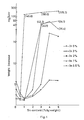
- Fig. 1 is a graphic representation corresponding to Table 1.
- Provision of the insoluble anode made of an alloy having high corrosion-resistance and low melting point that is well adaptive to the high current density condition allows plating as well as production of high quality foil with high productivity by facilitating the bath control. Specifically, such effect is achieved by:
Abstract
Description
- The present invention relates to an insoluble anode made of lead alloy and, more particularly, to an insoluble anode made of Pb-In-Sn alloy exhibiting a high corrosion resistance in sulfuric bath.
- Electroplating techniques are essential in industry for provision of corrosion resistance and other various purposes. It has been common practice to electroplate the object to the plated such as a strip of steel or copper sheet with Zn, Sn, Ni, Cu, Fe or the other metals or alloys thereof. Among these, zinc electroplating of steel has rapidly come into wide use, and demand therefor has increased in the automotive and household electric appliance fields, etc.
- Particularly in zinc electroplating of the car body, an electroplating operation using a high current density has recently been adopted to achieve so-called thick zinc plating with an increased amount of zinc deposited. For such zinc electroplating, a insoluble anode has usually been used. However, not only to adapt the anode for the high current density condition but also to eliminate problems attributable to use of a insoluble anode, for example, complicated control and maintenance of the plating bath due to rapidly enlarged electrode pitch, the insoluble anode has been emphasized and the conversion from the soluble anode to the insoluble anode is progressing steadily.
- The insoluble anode has also found its application in electrolytic formation of metallic, particularly, copper foil. In such electrolytic copper foil formation of the prior art, it has typically been provided that the insoluble anode is disposed so as to be opposed to and spaced by a predetermined distance from a drum made, for example, of titanium along a peripheral segment defined by 3 to 6 o'clock position to 6 to 9 o'clock position. A solution of copper sulfate has been circulated through a gap defined between the drum serving as the cathode and the insoluble anode to achieve electrodeposition of copper on the peripheral segment of the drum. The copper foil thus formed by the continuous electrodeposition of copper on said drum has been peeled off. In view of the fact that the electronics industry requires a large quantity of copper foil, operation using a current density higher than that which has been conventionally used is now under review with respect to improvement of the productivity.
- As will be appreciated, the insoluble anode occupies an important position in the electrolytic process such as plating and foil formation.
- Most of the well-known insoluble anodes are those made of lead, since lead is corrosion-resistant of plating bath or foil formation electrolytic bath conditions and there is produced, as a result of plating energization, lead dioxide on the surface of the anode, which functions as an effective discharge surface.
- However, such an insoluble anode of the prior art has proved to have a serious drawback in that said lead dioxide produced during the process of plating is easily separated from the lead surface due to its internal strain.
- Now the prior art will be discussed, particularly with respect to the electroplating. As a countermeasure to avoid the separation of lead dioxide from the lead surface, use of a lead alloy containing therein various alloy elements has been proposed. Among various types of such a lead alloy system, a Pb-In alloy system has been considered as a typical one of the potentially useful lead alloy systems. For example, Japanese Provisional Publication No. 59-28598 discloses Pb-0.5 to 10% In or Pb-0.5 to 10% Ag. However, the Pb-In alloy system exhibits unsatisfactory corrosion-resistance and, accordingly, this prior art proposes addition of Ag in order to improve the corrosion-resistance.
- Nevertheless, Ag is not necessarily preferable as the element added to the insoluble anode and its effect to improve the corrosion-resistance of this anode is not adequate, because:
- (A) Ag is one of the expensive precious metals, and
- (B) Ag has a melting point higher than that of Pb.
- Furthermore, such a lead alloy, even with Ag added, cannot exhibit the desired corrosion-resistance, particularly under a high current density condition.
- As has been mentioned at the beginning, this field of industry recently has developed a tendency to adopt the operation performed under a high current density condition rather than one under a low current density condition in various electrolytic operations such as electroplating and electrolytic foil formation. Accordingly, there is a serious demand for development of a low melting point anode exhibiting excellent corrosion-resistance and facilitating fabrication as well as working not only under said low current density condition but also under said high current density condition.
- In view of such situation, a principal object of the present invention is to develop an improved insoluble anode made of lead alloy exhibiting a high corrosion-resistance even under a high current density condition and containing neither expensive precious metals nor elements having their respective melting points higher than that of lead.
- Zealous effort of the inventors directed to the object as set forth above has revealed the fact that use of In with Sn is very advantageous to achievement of said objective. In has a melting point of 156°C and Sn has a melting point of 232°C, both being lower than the 327°C melting point of Pb. It is a surprising, significant discovery that these two additive elements having such low melting points may be exclusively used to obtain a desired anode exhibiting an excellent corrosion-resistance even under the high current density condition. Experiments have revealed that a combination of In (0.01 to 5% by weight) with Sn (0.01 to 5% by weight) is effective.
- Based on this knowledge, the present invention provides an insoluble anode including a discharging surface made of lead alloy containing In of 0.01 to 5% by weight, Sn of 0.01 to 5% by weight, and the rest consisting of lead and inevitable impurities.
- The expression "high current density" as used herein should be understood to cover the order of current density that is 100A/dm² or higher, normally 160A/dm² or higher, and most preferably 200A/dm². In connection with the formation of foil, this expression should be understood to cover the current density of 50A/dm² or higher.
- The anode constructed in accordance with the present invention exhibits a high corrosion resistance even under a high current density condition and serves as a functional type of electrode adapted for the high current recently used more often, with an advantageous result in various applications such as metallic electroplating, electrolytic formation of metallic foil and electrolytic refining. The anode of the present invention is useful particularly for thick zinc electroplating and electrolytic formation of copper foil. Use of the electrode constructed according to the present invention makes it possible to improve productivity such as by acceleration of production line speed and speed-up of plating film or formation of metallic foil. At the same time, it provides various advantages, as for example, an effective reduction of potential corrosion prolongs the useful life of the electrode and facilities control and maintenance of the plating bath.
-
- Fig. 1 graphically illustrates a relationship between the In content (% by weight) and the weight decrease (mg/A hr) with respect to several levels of Sn content.
- According to the present invention, In in the amount of 0.01 to 5%, preferably 0.5 to 4% by weight and Sn in the amount of 0.01 to 5%, preferably of 0.5 to 2% by weight, are added to Pb. Addition of In to Pb results in improvement of the corrosion-resistance and the addition of Sn to the Pb-In alloy containing In at any one of the selective ratios within the range as defined above, results in a remarkable improvement of the corrosion-resistance within the specified quantity range of the Sn addition. Accordingly, the optimum quantity of Sn addition is selected in accordance with the particular quantitative level of In addition. As will be described more in detail with respect to the Example, a corrosion-resistance improving effect, for example as shown below, is obtained (pure Pb exhibited a weight decrease of 8.5mg/A hr):
In(%) Sn(%) weight decrease(mg/a hr) 0.5 1 to 2 1.5 to 2.1 1 0.5 to 2 1.8 to 2.4 2 0.5 to 1 1.3 to 1.6 3 0.5 to 1 1.3 - The minimum level of In addition required to provide the expected effect is 0.01%. When added in combination with Sn, the effect of In is saturated when added in excess of 5%. Sn provides its expected effect at and above 0.01% in combination with In, but provides a reverse effect when added in excess of 5%.
- As has previously been described, the Pb-In-Sn alloy composed in accordance with the present invention is characterized by:
- (A) being able to exhibit an excellent corrosion-resistance even under the high current density condition, as evidenced by an extremely small weight decrease of 1/8 to 1/9 relative to that of pure Pb.
- (B) being a low melting point material obtained by the addition of Pb of In and Sn, both having melting points lower than that of Pb, an insoluble anode exclusively composed of these elements having low melting points, is significantly advantageous. For example, the process of alloying is facilitated. The base metal is protected, when the anode is made of a base metal coated with the alloy in question and a potential oxidation loss is reduced during remelting after recovery. The working process such as rolling is facilitated; and
- (C) containing none of the expensive precious metals that have conventionally been used.
- The present invention covers the anode using melted lead alloy of a predetermined composition. The anode can be encased by rolling lead onto the desired anode as a whole. The anode core formed from a base material, which core may be iron or copper, for example, is coated with a highly corrosion-resistant metal such as titanium, niobium, tantalum or comprised of a single piece of suitable corrosion-resistant material by coating said base material on one side of both sides with said lead alloy. Concerning the method of coating, the present invention includes a wide selection of methods. For example, the method by which said lead alloy is deposited directly onto the base material as by means of TIG (tungsten inert gas) technique and the method by which the base material is surface-treated as, for example, by soldering or electroplating, then said lead alloy is deposition-padded onto said treated surface.
- It is essential that at least the discharging surface of the anode by made of the alloy composed in accordance with the present invention.
- The insoluble anode is preferably to the soluble anode for the various electrolytic operations such as electroplating and foil formation, since the former has many advantages as set forth below.
-
- (1) adaptability for the high current density condition making it possible to improve production line speed (i.e., to shorten a production line) for plating or foil formation and thereby to speed up formation of plating film or foil, particularly in thick plating and electrolytic copper foil formation;
- (2) suitability for simultaneous deposition of alloy metal plating;
- (3) ability to provide homogeneous and uniform plating film or foil; and
- (4) ability to reduce the rate of elution into the bath.
-
- (1) ability to maintain the electrode pitch substantially constant and thereby to facilitate the maintenance thereof;
- (2) simplification of the bath composition control; and
- (3) reduction in quantity of additives such as sludge precipitator.
- These advantages allow the plating product of improved quality to be obtained at a reasonably low cost. Such merits further increase as the corrosion-resistance of the insoluble anode increases.
- Molten lead alloy of the composition as shown in Table 1 was prepared by the conventional melting technique, then the molten lead alloy was cast and thereafter rolled into a sheet having a thickness of 3mm. A test material of 3mm thickness x 10mm width x 150mm was cut from said sheet as an anode. The electrolytic discharge area was 1.5cm². As a cathode, a pure lead sheet of 5mm thickness x 60mm width x 150mm length was used. More specifically, a pair of such cathodes were opposed to each other with interposition of the anode therebetween.
- A corrosion-resistance test was conducted in the following manner: With the anode and the cathodes immersed in a solution (pH=1.1) of sulfuric acid, acidified mirabilite previously prepared by adding 71g/l of Na₂SO₄ solution with sulfuric acid(1+1), a series of electrolytic tests were conducted under conditions of bath temperatures of 40°C to 60°C, impressed current of 3A, current density of 200A/dm², and duration of energization of 100 hrs. After each test, the anode was dried in a drying oven and the weight decrease of each tested anode was determined. Then, the weight decrease per unit ampere was calculated from the actual weight decrease of each tested anode. The result of the tests is summarized in Table 1. Fig. 1 is a graphic representation corresponding to Table 1.


- Provision of the insoluble anode made of an alloy having high corrosion-resistance and low melting point that is well adaptive to the high current density condition allows plating as well as production of high quality foil with high productivity by facilitating the bath control. Specifically, such effect is achieved by:
- (1) reduced extent of potential corrosion and resultant prolongation of a useful life of the anode (leading to a corresponding cost reduction);
- (2) reduced amount of potential corrosion resulting in reduction of days consumed by readjustment of the gap distance;
- (3) reduced amount of potential corrosion resulting in simplified bath composition control;
- (4) reduced quantity of additives required such as sludge precipitator (leading to a corresponding cost reduction);
- (5) improved product quality;
- (6) facilitation of alloying and a correspondingly reduced cost;
- (7) base metal of the anode being free from any deformation during welding or padding thereto;
- (8) reduced loss due to oxidation occurring during remelt after recovery;
- (9) facilitation of working such as rolling, extrusion, severance or welding; and
- (10) reduced amount of potential corrosion, resulting in the ability to provide a thin and light product.
Claims (8)
Priority Applications (1)
| Application Number | Priority Date | Filing Date | Title |
|---|---|---|---|
| DE19883851140 DE3851140T2 (en) | 1988-03-31 | 1988-03-31 | Insoluble lead alloy anode. |
Applications Claiming Priority (1)
| Application Number | Priority Date | Filing Date | Title |
|---|---|---|---|
| JP61241419A JPS6396299A (en) | 1986-10-13 | 1986-10-13 | Insoluble anode made of lead alloy |
Publications (2)
| Publication Number | Publication Date |
|---|---|
| EP0335989A1 true EP0335989A1 (en) | 1989-10-11 |
| EP0335989B1 EP0335989B1 (en) | 1994-08-17 |
Family
ID=17074011
Family Applications (1)
| Application Number | Title | Priority Date | Filing Date |
|---|---|---|---|
| EP88105286A Expired - Lifetime EP0335989B1 (en) | 1986-10-13 | 1988-03-31 | Insoluble anode made of lead alloy |
Country Status (3)
| Country | Link |
|---|---|
| US (1) | US4867858A (en) |
| EP (1) | EP0335989B1 (en) |
| JP (1) | JPS6396299A (en) |
Cited By (1)
| Publication number | Priority date | Publication date | Assignee | Title |
|---|---|---|---|---|
| WO2023242448A1 (en) | 2022-06-17 | 2023-12-21 | Podadera Dominguez Francisco | Lift module for vertical take-off and landing aircraft and aircraft incorporating such a module |
Families Citing this family (4)
| Publication number | Priority date | Publication date | Assignee | Title |
|---|---|---|---|---|
| JPS6425998A (en) * | 1987-07-20 | 1989-01-27 | Sumitomo Metal Ind | Insoluble pb alloy anode |
| JPH028386A (en) * | 1988-06-27 | 1990-01-11 | Mitsui Toatsu Chem Inc | Method for electrolytically reducing m-hydroxybenzoic acid |
| JPH0277599A (en) * | 1988-09-12 | 1990-03-16 | Nippon Steel Corp | Insoluble electrode for continuously electrogalvanizing metallic strip and production thereof |
| DE4319951A1 (en) * | 1993-06-16 | 1994-12-22 | Basf Ag | Electrode consisting of an iron-containing core and a lead-containing coating |
Citations (1)
| Publication number | Priority date | Publication date | Assignee | Title |
|---|---|---|---|---|
| GB1294174A (en) * | 1969-06-05 | 1972-10-25 | M & T Chemicals Inc | Improvements in or relating to electrodepositing chromium using lead base alloys |
Family Cites Families (6)
| Publication number | Priority date | Publication date | Assignee | Title |
|---|---|---|---|---|
| JPS5189844A (en) * | 1975-02-04 | 1976-08-06 | DENKAIKUROMEETOSHORYODENKYOKU | |
| SE397155B (en) * | 1976-02-27 | 1977-10-17 | Tudor Ab | GRAY FOR POSITIVE ELECTROD TO ELECTRIC LEAD ACCUMULATOR |
| JPS57126935A (en) * | 1981-01-27 | 1982-08-06 | Matsushita Electric Works Ltd | Composition of electrode material |
| JPS6024197B2 (en) * | 1982-08-05 | 1985-06-11 | 住友金属工業株式会社 | Pb alloy insoluble anode for electroplating |
| JPS59193866U (en) * | 1983-06-13 | 1984-12-22 | 高安 清澄 | insoluble lead electrode |
| JPS6026635A (en) * | 1983-07-26 | 1985-02-09 | Sumitomo Metal Ind Ltd | Pb alloy for electrode for electroplating |
-
1986
- 1986-10-13 JP JP61241419A patent/JPS6396299A/en active Granted
-
1988
- 1988-03-16 US US07/168,925 patent/US4867858A/en not_active Expired - Fee Related
- 1988-03-31 EP EP88105286A patent/EP0335989B1/en not_active Expired - Lifetime
Patent Citations (1)
| Publication number | Priority date | Publication date | Assignee | Title |
|---|---|---|---|---|
| GB1294174A (en) * | 1969-06-05 | 1972-10-25 | M & T Chemicals Inc | Improvements in or relating to electrodepositing chromium using lead base alloys |
Non-Patent Citations (1)
| Title |
|---|
| PATENT ABSTRACTS OF JAPAN, vol. 8, no. 114 (C-225)[1551], 26th May 1984; & JP-A-59 028 598 (SUMITOMO KINZOKU KOGYO K.K.) 15-02-1984 * |
Cited By (1)
| Publication number | Priority date | Publication date | Assignee | Title |
|---|---|---|---|---|
| WO2023242448A1 (en) | 2022-06-17 | 2023-12-21 | Podadera Dominguez Francisco | Lift module for vertical take-off and landing aircraft and aircraft incorporating such a module |
Also Published As
| Publication number | Publication date |
|---|---|
| EP0335989B1 (en) | 1994-08-17 |
| JPS6396299A (en) | 1988-04-27 |
| US4867858A (en) | 1989-09-19 |
| JPH0125398B2 (en) | 1989-05-17 |
Similar Documents
| Publication | Publication Date | Title |
|---|---|---|
| Felder et al. | Lead alloys for permanent anodes in the nonferrous metals industry | |
| KR100396172B1 (en) | Electrowinning anodes which rapidly produce a protective oxide coating | |
| US4272339A (en) | Process for electrowinning of metals | |
| EP0335989B1 (en) | Insoluble anode made of lead alloy | |
| US2923671A (en) | Copper electrodeposition process and anode for use in same | |
| JP2529557B2 (en) | Lead alloy insoluble anode | |
| US4923573A (en) | Method for the electro-deposition of a zinc-nickel alloy coating on a steel band | |
| US4814048A (en) | Pb alloy insoluble anode and continuous electroplating of zinc using it | |
| Pradhan et al. | Effect of zinc on the electrocrystallization of cobalt | |
| US3947344A (en) | Inert anode | |
| JP2577965B2 (en) | Insoluble anode material | |
| KR920002998B1 (en) | Insoluble anode of a lead-alloy | |
| JP2639950B2 (en) | Insoluble anode material | |
| JPS6024197B2 (en) | Pb alloy insoluble anode for electroplating | |
| JPS6396297A (en) | Insoluble anode made of lead alloy | |
| JPS63243300A (en) | Insoluble anode for electroplating | |
| JPH01152294A (en) | Production of material for insoluble anode | |
| JPS6396294A (en) | Production of steel sheet having excellent weldability and corrosion resistance | |
| JPS6026836B2 (en) | Manufacturing method of zinc-nickel alloy plated steel sheet | |
| JP3258848B2 (en) | Method for removing metal impurity ions in electrogalvanizing bath | |
| JPS6333594A (en) | Conductor roll for galvanizing apparatus | |
| JPH0525000B2 (en) | ||
| JPH05279891A (en) | Method for electrogalvanizing aluminum strip and device therefor | |
| Subramaniyan | Electrodeposition of copper-lead alloys from a methanesulfonic acid electrolyte/Balachandar a/l Subramaniyan | |
| JP2001011555A (en) | Aluminum alloy for cathode |
Legal Events
| Date | Code | Title | Description |
|---|---|---|---|
| PUAI | Public reference made under article 153(3) epc to a published international application that has entered the european phase |
Free format text: ORIGINAL CODE: 0009012 |
|
| AK | Designated contracting states |
Kind code of ref document: A1 Designated state(s): BE CH DE FR GB LI NL |
|
| 17P | Request for examination filed |
Effective date: 19891228 |
|
| 17Q | First examination report despatched |
Effective date: 19910415 |
|
| GRAA | (expected) grant |
Free format text: ORIGINAL CODE: 0009210 |
|
| AK | Designated contracting states |
Kind code of ref document: B1 Designated state(s): BE CH DE FR GB LI NL |
|
| REF | Corresponds to: |
Ref document number: 3851140 Country of ref document: DE Date of ref document: 19940922 |
|
| ET | Fr: translation filed | ||
| PG25 | Lapsed in a contracting state [announced via postgrant information from national office to epo] |
Ref country code: LI Effective date: 19950331 Ref country code: GB Effective date: 19950331 Ref country code: CH Effective date: 19950331 |
|
| PLBE | No opposition filed within time limit |
Free format text: ORIGINAL CODE: 0009261 |
|
| STAA | Information on the status of an ep patent application or granted ep patent |
Free format text: STATUS: NO OPPOSITION FILED WITHIN TIME LIMIT |
|
| 26N | No opposition filed | ||
| PG25 | Lapsed in a contracting state [announced via postgrant information from national office to epo] |
Ref country code: NL Effective date: 19951001 |
|
| GBPC | Gb: european patent ceased through non-payment of renewal fee |
Effective date: 19950331 |
|
| REG | Reference to a national code |
Ref country code: CH Ref legal event code: PL |
|
| NLV4 | Nl: lapsed or anulled due to non-payment of the annual fee |
Effective date: 19951001 |
|
| PGFP | Annual fee paid to national office [announced via postgrant information from national office to epo] |
Ref country code: FR Payment date: 20000325 Year of fee payment: 13 |
|
| PGFP | Annual fee paid to national office [announced via postgrant information from national office to epo] |
Ref country code: DE Payment date: 20000331 Year of fee payment: 13 |
|
| PGFP | Annual fee paid to national office [announced via postgrant information from national office to epo] |
Ref country code: BE Payment date: 20000428 Year of fee payment: 13 |
|
| PG25 | Lapsed in a contracting state [announced via postgrant information from national office to epo] |
Ref country code: BE Free format text: LAPSE BECAUSE OF NON-PAYMENT OF DUE FEES Effective date: 20010331 |
|
| BERE | Be: lapsed |
Owner name: YOSHIZAWA LA K.K. Effective date: 20010331 |
|
| PG25 | Lapsed in a contracting state [announced via postgrant information from national office to epo] |
Ref country code: FR Free format text: LAPSE BECAUSE OF NON-PAYMENT OF DUE FEES Effective date: 20011130 |
|
| REG | Reference to a national code |
Ref country code: FR Ref legal event code: ST |
|
| PG25 | Lapsed in a contracting state [announced via postgrant information from national office to epo] |
Ref country code: DE Free format text: LAPSE BECAUSE OF NON-PAYMENT OF DUE FEES Effective date: 20020101 |