EP0335926B1 - Vorrichtung zur befestigung von perforierlinien an zylindern bei druckmaschinen - Google Patents
Vorrichtung zur befestigung von perforierlinien an zylindern bei druckmaschinen Download PDFInfo
- Publication number
- EP0335926B1 EP0335926B1 EP88908140A EP88908140A EP0335926B1 EP 0335926 B1 EP0335926 B1 EP 0335926B1 EP 88908140 A EP88908140 A EP 88908140A EP 88908140 A EP88908140 A EP 88908140A EP 0335926 B1 EP0335926 B1 EP 0335926B1
- Authority
- EP
- European Patent Office
- Prior art keywords
- pressure
- perforating
- clamping strip
- cylinder
- groove
- Prior art date
- Legal status (The legal status is an assumption and is not a legal conclusion. Google has not performed a legal analysis and makes no representation as to the accuracy of the status listed.)
- Expired - Lifetime
Links
- 238000007639 printing Methods 0.000 title claims abstract description 10
- 239000007788 liquid Substances 0.000 claims abstract description 4
- 229920001169 thermoplastic Polymers 0.000 claims abstract description 3
- 239000004416 thermosoftening plastic Substances 0.000 claims abstract description 3
- 239000000463 material Substances 0.000 claims description 13
- 239000004033 plastic Substances 0.000 claims description 6
- 229920003023 plastic Polymers 0.000 claims description 6
- -1 polyethylene Polymers 0.000 claims description 6
- 229920001296 polysiloxane Polymers 0.000 claims description 4
- 239000004698 Polyethylene Substances 0.000 claims description 3
- XTXRWKRVRITETP-UHFFFAOYSA-N Vinyl acetate Chemical compound CC(=O)OC=C XTXRWKRVRITETP-UHFFFAOYSA-N 0.000 claims description 2
- BZHJMEDXRYGGRV-UHFFFAOYSA-N Vinyl chloride Chemical compound ClC=C BZHJMEDXRYGGRV-UHFFFAOYSA-N 0.000 claims description 2
- 229920001577 copolymer Polymers 0.000 claims description 2
- 238000006073 displacement reaction Methods 0.000 claims description 2
- 238000002156 mixing Methods 0.000 claims description 2
- 229920000573 polyethylene Polymers 0.000 claims description 2
- 229920002725 thermoplastic elastomer Polymers 0.000 claims description 2
- 239000012530 fluid Substances 0.000 claims 1
- 229920002994 synthetic fiber Polymers 0.000 claims 1
- 230000003247 decreasing effect Effects 0.000 abstract 1
- 230000005540 biological transmission Effects 0.000 description 12
- 238000013461 design Methods 0.000 description 7
- 230000006378 damage Effects 0.000 description 4
- 238000000034 method Methods 0.000 description 4
- 230000008569 process Effects 0.000 description 4
- 238000010276 construction Methods 0.000 description 3
- 239000003921 oil Substances 0.000 description 3
- 229910000831 Steel Inorganic materials 0.000 description 2
- 238000004873 anchoring Methods 0.000 description 2
- 230000008901 benefit Effects 0.000 description 2
- 230000006835 compression Effects 0.000 description 2
- 238000007906 compression Methods 0.000 description 2
- 230000000694 effects Effects 0.000 description 2
- 230000009467 reduction Effects 0.000 description 2
- 239000010959 steel Substances 0.000 description 2
- 230000004323 axial length Effects 0.000 description 1
- 230000008859 change Effects 0.000 description 1
- 230000001427 coherent effect Effects 0.000 description 1
- 238000004891 communication Methods 0.000 description 1
- 238000004132 cross linking Methods 0.000 description 1
- 238000011161 development Methods 0.000 description 1
- 230000018109 developmental process Effects 0.000 description 1
- 229920001971 elastomer Polymers 0.000 description 1
- 239000000806 elastomer Substances 0.000 description 1
- 230000002349 favourable effect Effects 0.000 description 1
- 230000005484 gravity Effects 0.000 description 1
- 238000010438 heat treatment Methods 0.000 description 1
- 239000010720 hydraulic oil Substances 0.000 description 1
- 238000003780 insertion Methods 0.000 description 1
- 230000037431 insertion Effects 0.000 description 1
- 230000007774 longterm Effects 0.000 description 1
- 229920001684 low density polyethylene Polymers 0.000 description 1
- 235000013372 meat Nutrition 0.000 description 1
- 230000000149 penetrating effect Effects 0.000 description 1
- 230000036316 preload Effects 0.000 description 1
- 238000003825 pressing Methods 0.000 description 1
- 238000012545 processing Methods 0.000 description 1
- 230000004044 response Effects 0.000 description 1
- 238000007789 sealing Methods 0.000 description 1
- 239000007787 solid Substances 0.000 description 1
- 239000012815 thermoplastic material Substances 0.000 description 1
Images

Classifications
-
- F—MECHANICAL ENGINEERING; LIGHTING; HEATING; WEAPONS; BLASTING
- F15—FLUID-PRESSURE ACTUATORS; HYDRAULICS OR PNEUMATICS IN GENERAL
- F15B—SYSTEMS ACTING BY MEANS OF FLUIDS IN GENERAL; FLUID-PRESSURE ACTUATORS, e.g. SERVOMOTORS; DETAILS OF FLUID-PRESSURE SYSTEMS, NOT OTHERWISE PROVIDED FOR
- F15B7/00—Systems in which the movement produced is definitely related to the output of a volumetric pump; Telemotors
-
- B—PERFORMING OPERATIONS; TRANSPORTING
- B26—HAND CUTTING TOOLS; CUTTING; SEVERING
- B26D—CUTTING; DETAILS COMMON TO MACHINES FOR PERFORATING, PUNCHING, CUTTING-OUT, STAMPING-OUT OR SEVERING
- B26D7/00—Details of apparatus for cutting, cutting-out, stamping-out, punching, perforating, or severing by means other than cutting
- B26D7/26—Means for mounting or adjusting the cutting member; Means for adjusting the stroke of the cutting member
- B26D7/2614—Means for mounting the cutting member
-
- B—PERFORMING OPERATIONS; TRANSPORTING
- B26—HAND CUTTING TOOLS; CUTTING; SEVERING
- B26D—CUTTING; DETAILS COMMON TO MACHINES FOR PERFORATING, PUNCHING, CUTTING-OUT, STAMPING-OUT OR SEVERING
- B26D7/00—Details of apparatus for cutting, cutting-out, stamping-out, punching, perforating, or severing by means other than cutting
- B26D7/26—Means for mounting or adjusting the cutting member; Means for adjusting the stroke of the cutting member
- B26D7/2628—Means for adjusting the position of the cutting member
Definitions
- the invention relates to a device for attaching perforation lines to cylinders in printing presses with the generic features mentioned in the preamble of claim 1.
- the bellows cylinders have a central extension which can be screwed into the thread of the transverse bore; the entire bellows cylinder is located outside of the insert and therefore also determines the distance that the threaded holes in the insert must take due to its size, namely its maximum outside diameter.
- metallic bellows cylinders were used in place of the usual piston-cylinder units, so that the risk of leakage of led oil, which occurs particularly at high pressures, is as unconnected as possible.
- the channel system thus formed is then filled with a pressure medium - standard hydraulic oil - and the longitudinal bore in the insert or in the terminal strip thus formed is closed on one side with a normal screw that forms a plug, while on the opposite end of the insert a special screw is used which, depending on how deeply it is screwed into its associated thread, generates a corresponding pressure in the duct system and thus in the bellows cylinders, which first provides the pretensioning force for initially holding and aligning the knife and then after adjustment the final clamping force for holding the knife.
- the problem with such a clamping strip design can be the fact that the respective bellows cylinders, which generate the preload pressure and finally the final holding pressure for the knife or the perforation line, are placed on the insert from the outside, and practically completely fill the corresponding groove of the perforating cylinder in terms of its size, even in the radial direction.
- This can not only lead to injuries in the bellows structure during rough operation, but also requires comparatively wide receiving grooves for the entire printing system, so that only a few, for example, a total of six perforation lines receiving grooves can be arranged over the circumference of the cylinder.
- the rounding of the perforating cylinder already plays a role here, so that the inserts or pressure bars are essentially trapezoidal in cross section. Furthermore, due to the construction of the bellows cylinders, a certain wall flexibility is necessary, which is necessary so that the bellows cylinders can also fulfill the function of a piston movement when the pressure in the interior of the bellows increases due to their wave-shaped, at least in the axial direction flexible wall .
- the object of the invention is therefore to avoid the above-mentioned disadvantages of the known device and to ensure that the perforation lines are fixed to the perforation cylinder in a manner that is safe against loads and leaking oil, while still being simple in construction.
- the invention has the advantage, on the one hand, that the required groove width on the perforating cylinder need not be greater than the thickness of the clamping strip plus the thickness of the perforating line, because the clamping strip also serves as a cylinder housing for the pistons of the tensioning devices it receives. It is also particularly advantageous that precisely where high and highest pressures occur, which can build up to extreme values of several 100 bar to generate the required clamping force, there are no flexible wall areas, but the pressure is only inside the terminal strip, i.e. in the continuous connection channel and in the pressure chambers of the clamping cylinders. It is particularly advantageous that no leakage oil problems occur, since the result is that a soft-elastic solid body is used as the pressure transmission medium, which always remains "coherent".
- the terminal block according to the invention is small and narrow, it is also subject to a comparatively low weight and less severe effects of gravity when working the perforating cylinder. Damage in the pressure medium duct system of each terminal strip is practically impossible; likewise, each clamping strip can be inserted into the groove of the perforating cylinder which receives it so that no protruding parts or parts which then necessarily follow the shape of the perforating cylinder are exposed to the outside, with the exception of the edge of the clamped perforating line.
- the pressure screw when screwed in which the pistons arranged displaceably in the terminal block in the transverse direction are pressurized, is accessible radially from the outside, that is to say seen from the circumferential direction of the perforating cylinder.
- the design of the terminal strip with a lower shoulder or a collar on which the perforation line, which extends over the length of the perforating cylinder, is seated, is particularly advantageous, so that the height adjustment of the terminal strip and its subsequent positive and possibly positive anchoring at the same time also Height adjustment of the assigned perforation line and its anchoring conveyed.
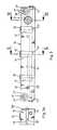
- FIGS. 1 to 6 Purpose of the device according to the invention shown in FIGS. 1 to 6, to the details of which reference is expressly made in its entirety, generally designated 10, for fastening one or more perforation lines 11 to the perforation cylinder 26, one in FIG. 1 through this and through the anvil cylinder 26 'Represented printing machine, by means of which pre-prints prepared in a continuous printing process by transverse perforations for separating from one another can be produced without major screwing work quickly and without complications with high precision with respect to the anvil cylinder 26' and can be securely fastened.
- 10 Purpose of the device according to the invention shown in FIGS. 1 to 6, to the details of which reference is expressly made in its entirety, generally designated 10, for fastening one or more perforation lines 11 to the perforation cylinder 26, one in FIG. 1 through this and through the anvil cylinder 26 'Represented printing machine, by means of which pre-prints prepared in a continuous printing process by transverse perforations for separating from one another can
- This fastening device 10 is designed as a clamping strip, which can be inserted into a groove 25 of the perforating cylinder 26, into which the perforating line 11 is inserted, and can be braced in this groove 25, as a result of which the perforating line 11 is also fixed in its desired position.
- Such perforation line 11 is formed in a typical design as a flat bar-shaped knife, the - straight line - cutting edge 11 'very precisely parallel to the in turn parallel to the axis of rotation 32 of the anvil cylinder 26' extending line 33 of the anvil cylinder 26 ', along which the to producing perforation eg in a paper tape, in each case in the longitudinal format spacing of a form to be produced.
- the perforating line 11 Since the cutting edge should generally push through to the outer surface 35 of the anvil cylinder 26 ', the perforating line 11 must be fixed very firmly in the groove 25 of the perforating cylinder 26, since a large number of cutting or perforation processes are to be carried out during operation of the printing press are.
- the groove 25 provided for receiving the perforation line 11 and the clamping strip 10 extends, viewed in the direction of the axis of rotation 34 of the perforating cylinder 26, over its entire axial length and is milled into the steel cylinder 26 with the profile cross section shown in FIG. 1 .
- This groove 25 has a substantially U-shaped clear cross section, the one groove cheek 36, against which the perforation line 11 is pressed by means of the clamping strip 10, runs exactly radially, ie along a radial plane containing the axis of rotation 34 of the perforating cylinder.
- the groove cheek 37 which runs parallel to this groove cheek 36 and on which the clamping strip can be supported by means of clamping elements to be explained in more detail below, is measured somewhat from the lateral surface 37 ⁇ of the perforating cylinder, somewhat shorter than the radial groove cheek 36 and closes via an obliquely extending one Cheek section 38 on the groove base 39 running at right angles to the radial groove cheek 36, so that the cross section of the groove 25 tapers somewhat in the radially inner part.
- the terminal block is designed as a prismatic steel rod, which has parallel to the groove cheeks 36 and 37, the oblique cheek section 38 and the groove base 39 and has a geometrically similar cross-section to the clear cross section of the groove 25, the clamping strip 10 being designed in this way is that it "fills" the clear cross section of the groove 25 as far as possible, such that only gaps with a small width remain between the terminal block 10 and the boundary surfaces of the groove 25.
- the groove 25 has a clear width w of 22.5 mm measured between its parallel groove flanks 36 and 37 and a depth t of 33 mm measured along its radial groove flank 36.
- the inclined cheek section 38 encloses an angle ⁇ of 60 ° with the radial plane in which the radial groove cheek 36 runs.
- the area t 'of the depth t of the groove 25 over which the obliquely extending cheek portion 38 extends is 6 mm in the special embodiment shown.
- the inner region of the terminal block 10 is provided on its side facing the perforation line 11 with a collar or shoulder 27, on which the perforation line 11 with its back edge 11 'can be supported radially over its entire length.
- the perpendicular to the adjacent surface of the perforation line 36 '36 of the terminal block 10 measured height of this paragraph 27 of the terminal block is slightly less than the thickness of the perforation line 11, which in typical design has a value of 0.7 mm.
- the clamping devices by means of which the clamping strip 10 and with this also the perforation line 11 in the groove 25 can be fixed in a load-proof manner, are, as can best be seen from FIG. 3, as pressure cylinders arranged at regular intervals over the length of the clamping strip 10 13 'formed, the pistons 13 are guided in a pressure-tight manner in transverse bores 12 of the terminal strip 10, the central bore axes 42 of which run at right angles to the mutually parallel groove cheeks 36 and 37 of the groove or the parallel boundary surfaces 36' and 37 'of the terminal strip 10.
- the transverse bores 12 are formed as, seen in the position of use of the terminal strip 10, blind holes open to the narrower groove cheek 37 of the groove 25, from which the pistons 13 protrude.
- Pressure chambers 43 delimited axially by the pistons and fixed to the housing through the inner sections of the blind bores 12 are in communicating connection with one another via a longitudinal bore 14 penetrating the terminal strip 10 in its longitudinal direction.
- the longitudinal bore 14 is hermetically sealed at its ends by plugs 14 '.
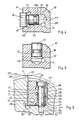
- the pressure chambers 43 of the pressure cylinder 13 'connecting longitudinal bore 14 is also, as shown in Fig. 4 in detail, with a pressure chamber 19 in communicating connection, which is fixed to the housing through the inner portion of a further blind bore 19' and axially movable by a piston 16a is limited, which is guided in the blind bore 19 'movable pressure-tight.
- This piston 16a is sealed by means of a ring seal 20 designed as a sliding seal against the bore 19 '.
- the central axis 44 of this blind bore 19 extends at right angles to the boundary surfaces 39' and 41 of the terminal strip 10 running parallel to the groove base 39.
- the blind bore 19 opens out on the anvil cylinder 26 'facing surface 41 of the terminal strip 10 with a threaded portion 21 whose inside diameter is somewhat is greater than the diameter of that section of the blind bore 19 'in which the piston 16a is guided so as to be displaceable in a pressure-tight manner.
- This threaded portion 21 is offset by a thread undercut 22 of conventional design against the portion of the blind bore 19 'forming the housing-fixed boundary of the pressure chamber 19', in which the piston 16a is guided so as to be displaceable in a pressure-tight manner.
- the pressure spaces 43 of the pressure cylinder 13 'communicating with each other via the bore 14' and the pressure space 19 which is also in communication with these spaces through the piston 16a are completely filled with a pressure medium, in which by turning the pressure screw 16 in the sense of a reduction of the pressure chamber 19 a high pressure can be built up, with which - via the bore 14 - also the pressure chambers 43 of the pressure cylinder 13 'are acted upon, thereby pressing the piston 13 against the groove cheek 37 and in response to this the clamping strip is pressed against the perforation line 11, which, depending on the size of the pressure generated by turning the pressure screw 16, is pressed more or less firmly against the radial groove flank 36 and is thereby fixed in its desired position.
- the axial extension 46 of the pressure screw 16, with which it is axially supported on a flat end face 47 of the piston 16a, is flat-spherical, so that there is only one support point lying on the central axis 44 and upon rotation of the pressure screw 16 in In the sense of an increase in pressure, no torque is exerted on the piston 16a in order to avoid rotation of the piston 16a itself and consequent wear of the ring seal 20.
- the terminal strip 10 is provided at its ends with a stepped bore, designated overall by 17, the arrangement of which can best be seen in FIG. 3 and the design is best shown in FIG. 6, to the details of which reference is hereby made.
- the central axes 47 of these stepped bores run, seen in the position of use of the terminal block 10, perpendicular to the groove bottom 39 of the groove 25 of the perforating cylinder 26.
- These stepped bores comprise a minimum diameter of the stepped bore 17 corresponding central section 17 ', to each of which a radial annular shoulder 48 or 49 Connect an outer bore section 17 ⁇ , which is open to the outside, or an inner bore section 17 ′′′ of larger diameter, which is open to the groove base 39.
- the outer bore section 17 ⁇ serves for the recessed receiving of the head 50 of a shoulder screw designated overall by 28, which has an adjoining the head, bolt-shaped shaft 51, the diameter of which is slightly smaller than the diameter of the central section 17 'of the respective stepped bore 17th
- This cylindrical-bolt-shaped shaft 51 of the respective shoulder screw 28 is followed by the diameter after the smaller, short threaded section 52 of the shoulder screw 28, with which it is screwed into a threaded bore 53 starting from the base 39 of the groove 25 until the Shoulder screw with the circular end face 54 of its bolt-shaped shaft 51, which sets it against the threaded section 52, is seated on the base 39 of the groove 25 of the perforating cylinder 26.
- the difference in lengths l and l ' determines the radial range of variation within which the position of the cutting edge 11' of the perforation line 11 can be changed or adapted to the course of the surface line 33 of the anvil cylinder 26 ', along which the perforation line - on the Shell surface 35 of the anvil cylinder 26 'seated - the adjacent - not shown - pierces or cuts through the material web.
- a "middle" position of the cutting edge 11 'of the perforation line 11 is shown, from which the perforation line 11, if necessary, can be disengaged from the groove 25 by a small distance h or by a small distance h' would be lowered in the groove 25 in the radial direction.
- a position corresponding approximately to the "center position" of the perforation line 11 shown is the position suitable for the cutting processing of the material web.
- the position of the perforation line 11 in the correct position is considerably facilitated by the configuration of the terminal strip 10 and its arrangement in the groove 25 of the perforating cylinder 26.
- Such an adjustment process can be carried out in such a way that the perforation line 11, while it is in its radially outermost position, which is marked by the ring shoulder 48 bearing against the screw head 50, so far in the direction of the arrow 57 in FIG. 1 - by turning the Perforating cylinder - is rotated that the cutting edge 11 'just abuts the anvil cylinder 26'.
- the pressure acting on the pistons 13 of the tensioning devices is increased to such an extent that the perforating strip, when the two cylinders 26 and 26 'are rotated in phase with one another, move somewhat into the groove 25 and thus their desired Position can be that, however, if by further turning the two cylinders 26 and 26 'the line contact of the perforation line 11 with the jacket 35 of the anvil cylinder 26' is canceled again, the terminal strip 10 is not pushed back into its radially outer position, but by the Pressurizing the piston 13 of the pressure cylinder 13 'remains in its target position.
- set screws 31 are provided, which are screwed into threaded bores 30, the Axes 58 run parallel to the axes 47 of the stepped bores 17.
- the terminal strip 10 As a largely incompressible pressure transmission means, via which a reduction in volume of the pressure chamber 19 that can be achieved by turning the pressure screws 16 and thus the spaces filled with pressure medium overall, in which the pistons 13 of the pressure cylinder 13 'act pressures implemented, is achieved, the terminal strip 10, generally speaking, a plastic fillable in liquid state is used, which solidifies after filling into a soft-elastic body.
- This soft-elastic pressure transmission body can be achieved by means of a thermoplastic, which is introduced in the molten state into the pressure chambers 19, 14 and 13 ', filling them completely and then, when it has cooled to the operating temperature of the machine, forms the pressure transmission body.
- Thermoplastic elastomers - suitable elastomers are in the scientific publication: Franck / Biederbick; Plastic Compendium, Second Edition, Würzburg: Vogel, Book Publishing 1988, page 282 ff.
- the pressure transmission body should have a Shore A hardness between 20 and 70, preferably between 30 and 50, at operating temperature.
- the elastic pressure transmission body filling the pressure spaces can also consist of soft PVC material or of a plasticized copolymer of vinyl chloride and vinyl acetate.
- Low density soft polyethylene (PE-LD) is also suitable for realizing the pressure transmission body.
- a cold-crosslinking material can also be used to produce the pressure body, for example a polysiloxane, the liquid starting products of which immediately after Mixing can be poured into the pressure chambers and there too network these filling rubber-elastic pressure transmission bodies.
- a pressure transmission body based on polysiloxane can no longer be removed from the terminal block 10, but it has the advantage of favorable pressure transmission properties and a high long-term stability, which makes "replacing" the pressure transmission body seem unnecessary anyway.
- Suitable polysiloxane materials are also described on page 228 ff. Of the publication mentioned.
- the fastening device according to the invention which consists of the terminal block 10 and - on the machine side - each from a receiving groove 25 for this terminal block, is constructed in a space-saving manner that, distributed over the circumference of a perforating cylinder 26, a plurality of terminal strips 10 can be arranged, the being along the circumference of the perforating cylinder measured distance of the terminal strips 10 and the perforating lines 11 is at least 50.8 mm (2 inches). It is achieved by the oblique course of the groove cheek section 38 of the groove 25 that, seen in the circumferential direction, successive grooves always have enough "meat" of the cylinder material to reliably prevent damage to the cylinder walls extending between two grooves 25.
Landscapes
- Engineering & Computer Science (AREA)
- Mechanical Engineering (AREA)
- Life Sciences & Earth Sciences (AREA)
- Forests & Forestry (AREA)
- Physics & Mathematics (AREA)
- Fluid Mechanics (AREA)
- General Engineering & Computer Science (AREA)
- Supply, Installation And Extraction Of Printed Sheets Or Plates (AREA)
- Perforating, Stamping-Out Or Severing By Means Other Than Cutting (AREA)
Priority Applications (1)
| Application Number | Priority Date | Filing Date | Title |
|---|---|---|---|
| AT88908140T ATE69988T1 (de) | 1987-09-23 | 1988-09-23 | Vorrichtung zur befestigung von perforierlinien an zylindern bei druckmaschinen. |
Applications Claiming Priority (2)
| Application Number | Priority Date | Filing Date | Title |
|---|---|---|---|
| DE19873731957 DE3731957A1 (de) | 1987-09-23 | 1987-09-23 | Vorrichtung zur befestigung von perforierlinien an zylindern bei druckmaschinen |
| DE3731957 | 1987-09-23 |
Publications (2)
| Publication Number | Publication Date |
|---|---|
| EP0335926A1 EP0335926A1 (de) | 1989-10-11 |
| EP0335926B1 true EP0335926B1 (de) | 1991-12-04 |
Family
ID=6336637
Family Applications (1)
| Application Number | Title | Priority Date | Filing Date |
|---|---|---|---|
| EP88908140A Expired - Lifetime EP0335926B1 (de) | 1987-09-23 | 1988-09-23 | Vorrichtung zur befestigung von perforierlinien an zylindern bei druckmaschinen |
Country Status (4)
| Country | Link |
|---|---|
| EP (1) | EP0335926B1 (enExample) |
| AT (1) | ATE69988T1 (enExample) |
| DE (2) | DE3731957A1 (enExample) |
| WO (1) | WO1989002813A1 (enExample) |
Families Citing this family (1)
| Publication number | Priority date | Publication date | Assignee | Title |
|---|---|---|---|---|
| DE102004011898A1 (de) * | 2004-03-11 | 2005-09-29 | Heidelberger Druckmaschinen Ag | Vorrichtung zum rotativen Bearbeiten von blattförmigen Materialien |
Family Cites Families (7)
| Publication number | Priority date | Publication date | Assignee | Title |
|---|---|---|---|---|
| DE222598C (enExample) * | ||||
| US2682306A (en) * | 1950-09-22 | 1954-06-29 | Schriber Machinery Company | Tab cutter |
| DE2021061C2 (de) * | 1970-04-29 | 1983-07-07 | Dr. Otto C. Strecker Kg, 6102 Pfungstadt | Messeranordnung für einen Querschneider |
| US3703117A (en) * | 1970-12-01 | 1972-11-21 | Maxson Automatic Mach | Rotary paper-cutter knife structure |
| FR2179572B1 (enExample) * | 1972-04-12 | 1976-04-30 | Jarret Jean | |
| DE2829732A1 (de) * | 1978-07-06 | 1980-01-17 | Scheer & Cie C F | Schneidwerkzeug |
| DE8506462U1 (de) * | 1985-03-06 | 1985-05-30 | Maschinenfabrik Goebel Gmbh, 6100 Darmstadt | Messerzylinder zum bearbeiten von bahnfoermigem gut |
-
1987
- 1987-09-23 DE DE19873731957 patent/DE3731957A1/de active Granted
-
1988
- 1988-09-23 DE DE8888908140T patent/DE3866696D1/de not_active Expired - Lifetime
- 1988-09-23 AT AT88908140T patent/ATE69988T1/de active
- 1988-09-23 WO PCT/DE1988/000588 patent/WO1989002813A1/de not_active Ceased
- 1988-09-23 EP EP88908140A patent/EP0335926B1/de not_active Expired - Lifetime
Also Published As
| Publication number | Publication date |
|---|---|
| WO1989002813A1 (fr) | 1989-04-06 |
| DE3731957C2 (enExample) | 1989-10-12 |
| EP0335926A1 (de) | 1989-10-11 |
| DE3866696D1 (de) | 1992-01-16 |
| DE3731957A1 (de) | 1989-04-13 |
| ATE69988T1 (de) | 1991-12-15 |
Similar Documents
| Publication | Publication Date | Title |
|---|---|---|
| EP0620084B1 (de) | Spannvorrichtung zum Spannen von Werkstücken | |
| EP2364813B1 (de) | Honwerkzeug | |
| DE3446974C2 (enExample) | ||
| DE69031837T2 (de) | Verstellbare spannvorrichtung | |
| DE4130811C2 (de) | Presse mit verstellbarem Hub | |
| DE2755425A1 (de) | Dichtung | |
| DE2942417A1 (de) | Innenzahnradmaschine | |
| DE2937972A1 (de) | Vorrichtung zum aufbringen einer flaechenpressung auf fortschreitende werkstuecke | |
| EP1179149B1 (de) | Dichtungsvorrichtung für einen mit druckmittel beaufschlagten kolben in einem arbeitszylinder | |
| DE1229480B (de) | Hydraulischer Grubenstempel | |
| DE4320668A1 (de) | Walzenmühle | |
| DE3341424C2 (de) | Antriebsvorrichtung | |
| EP1611380B1 (de) | Dichtungsanordnung | |
| DE2118033B2 (de) | Hydrostatische schmiervorrichtung fuer die zahneingriffsstellen von zylinderschnecke und schneckenzahnstange | |
| EP0335926B1 (de) | Vorrichtung zur befestigung von perforierlinien an zylindern bei druckmaschinen | |
| DE2008348B2 (de) | Verfahren und Vorrichtung zur Herstellung eines napfförmigen Werkstücks | |
| DE19645464B4 (de) | Mechanische Presse | |
| DE1577476A1 (de) | Hon-Dorn | |
| DE8517118U1 (de) | Hydraulische Schraubenmaschine | |
| EP0879663B1 (de) | Schneidwerkzeug mit zubehörfreier Schneidenhalterung | |
| EP0337145B1 (de) | Vorrichtung zur hydrostatischen Abstützung von Walzen eines Walzwerkes | |
| DE1951811A1 (de) | Verfahren und Einrichtung zum Lochstanzen | |
| DE2830463C2 (de) | Vorrichtung zum Verhindern von Leckverlusten an einem sich in eine Arbeitskammer erstreckenden kolbenartigen Stössel | |
| DE3807654A1 (de) | Verfahren und vorrichtung zum wechseln und/oder (wieder-) anfahren von in baustuecken gelagerten walzen, rollen, scheren oder dgl. | |
| DE9013190U1 (de) | Bohrer |
Legal Events
| Date | Code | Title | Description |
|---|---|---|---|
| PUAI | Public reference made under article 153(3) epc to a published international application that has entered the european phase |
Free format text: ORIGINAL CODE: 0009012 |
|
| AK | Designated contracting states |
Kind code of ref document: A1 Designated state(s): AT BE CH DE FR GB IT LI LU NL SE |
|
| 17P | Request for examination filed |
Effective date: 19890914 |
|
| 17Q | First examination report despatched |
Effective date: 19900711 |
|
| GRAA | (expected) grant |
Free format text: ORIGINAL CODE: 0009210 |
|
| AK | Designated contracting states |
Kind code of ref document: B1 Designated state(s): AT BE CH DE FR GB IT LI LU NL SE |
|
| REF | Corresponds to: |
Ref document number: 69988 Country of ref document: AT Date of ref document: 19911215 Kind code of ref document: T |
|
| PGFP | Annual fee paid to national office [announced via postgrant information from national office to epo] |
Ref country code: DE Payment date: 19911205 Year of fee payment: 5 |
|
| REF | Corresponds to: |
Ref document number: 3866696 Country of ref document: DE Date of ref document: 19920116 |
|
| ITF | It: translation for a ep patent filed | ||
| GBT | Gb: translation of ep patent filed (gb section 77(6)(a)/1977) | ||
| ET | Fr: translation filed | ||
| PGFP | Annual fee paid to national office [announced via postgrant information from national office to epo] |
Ref country code: GB Payment date: 19920921 Year of fee payment: 5 |
|
| PGFP | Annual fee paid to national office [announced via postgrant information from national office to epo] |
Ref country code: SE Payment date: 19920922 Year of fee payment: 5 |
|
| PGFP | Annual fee paid to national office [announced via postgrant information from national office to epo] |
Ref country code: AT Payment date: 19920928 Year of fee payment: 5 |
|
| PGFP | Annual fee paid to national office [announced via postgrant information from national office to epo] |
Ref country code: LU Payment date: 19920929 Year of fee payment: 5 |
|
| PGFP | Annual fee paid to national office [announced via postgrant information from national office to epo] |
Ref country code: NL Payment date: 19920930 Year of fee payment: 5 Ref country code: FR Payment date: 19920930 Year of fee payment: 5 |
|
| PLBE | No opposition filed within time limit |
Free format text: ORIGINAL CODE: 0009261 |
|
| STAA | Information on the status of an ep patent application or granted ep patent |
Free format text: STATUS: NO OPPOSITION FILED WITHIN TIME LIMIT |
|
| PGFP | Annual fee paid to national office [announced via postgrant information from national office to epo] |
Ref country code: BE Payment date: 19921013 Year of fee payment: 5 |
|
| 26N | No opposition filed | ||
| PGFP | Annual fee paid to national office [announced via postgrant information from national office to epo] |
Ref country code: CH Payment date: 19921130 Year of fee payment: 5 |
|
| EPTA | Lu: last paid annual fee | ||
| PG25 | Lapsed in a contracting state [announced via postgrant information from national office to epo] |
Ref country code: LU Free format text: LAPSE BECAUSE OF NON-PAYMENT OF DUE FEES Effective date: 19930923 Ref country code: GB Effective date: 19930923 Ref country code: AT Effective date: 19930923 |
|
| PG25 | Lapsed in a contracting state [announced via postgrant information from national office to epo] |
Ref country code: SE Effective date: 19930924 |
|
| PG25 | Lapsed in a contracting state [announced via postgrant information from national office to epo] |
Ref country code: LI Effective date: 19930930 Ref country code: CH Effective date: 19930930 Ref country code: BE Effective date: 19930930 |
|
| BERE | Be: lapsed |
Owner name: KILPER KARL Effective date: 19930930 |
|
| PG25 | Lapsed in a contracting state [announced via postgrant information from national office to epo] |
Ref country code: NL Effective date: 19940401 |
|
| NLV4 | Nl: lapsed or anulled due to non-payment of the annual fee | ||
| GBPC | Gb: european patent ceased through non-payment of renewal fee |
Effective date: 19930923 |
|
| PG25 | Lapsed in a contracting state [announced via postgrant information from national office to epo] |
Ref country code: FR Free format text: LAPSE BECAUSE OF NON-PAYMENT OF DUE FEES Effective date: 19940531 |
|
| REG | Reference to a national code |
Ref country code: CH Ref legal event code: PL |
|
| PG25 | Lapsed in a contracting state [announced via postgrant information from national office to epo] |
Ref country code: DE Effective date: 19940601 |
|
| REG | Reference to a national code |
Ref country code: FR Ref legal event code: ST |
|
| EUG | Se: european patent has lapsed |
Ref document number: 88908140.2 Effective date: 19940410 |
|
| PG25 | Lapsed in a contracting state [announced via postgrant information from national office to epo] |
Ref country code: IT Free format text: LAPSE BECAUSE OF NON-PAYMENT OF DUE FEES Effective date: 20050923 |