EP0335916B1 - Extrudeuse ainsi que procede pour la fabrication de pieces moulees manipulables en papier de rebut - Google Patents
Extrudeuse ainsi que procede pour la fabrication de pieces moulees manipulables en papier de rebut Download PDFInfo
- Publication number
- EP0335916B1 EP0335916B1 EP19880903821 EP88903821A EP0335916B1 EP 0335916 B1 EP0335916 B1 EP 0335916B1 EP 19880903821 EP19880903821 EP 19880903821 EP 88903821 A EP88903821 A EP 88903821A EP 0335916 B1 EP0335916 B1 EP 0335916B1
- Authority
- EP
- European Patent Office
- Prior art keywords
- intermediate conveyor
- waste paper
- worm
- conveying
- water
- Prior art date
- Legal status (The legal status is an assumption and is not a legal conclusion. Google has not performed a legal analysis and makes no representation as to the accuracy of the status listed.)
- Expired - Lifetime
Links
Images

Classifications
-
- B—PERFORMING OPERATIONS; TRANSPORTING
- B30—PRESSES
- B30B—PRESSES IN GENERAL
- B30B9/00—Presses specially adapted for particular purposes
- B30B9/30—Presses specially adapted for particular purposes for baling; Compression boxes therefor
- B30B9/3089—Extrusion presses
-
- B—PERFORMING OPERATIONS; TRANSPORTING
- B02—CRUSHING, PULVERISING, OR DISINTEGRATING; PREPARATORY TREATMENT OF GRAIN FOR MILLING
- B02C—CRUSHING, PULVERISING, OR DISINTEGRATING IN GENERAL; MILLING GRAIN
- B02C18/00—Disintegrating by knives or other cutting or tearing members which chop material into fragments
- B02C18/0007—Disintegrating by knives or other cutting or tearing members which chop material into fragments specially adapted for disintegrating documents
-
- B—PERFORMING OPERATIONS; TRANSPORTING
- B30—PRESSES
- B30B—PRESSES IN GENERAL
- B30B9/00—Presses specially adapted for particular purposes
- B30B9/30—Presses specially adapted for particular purposes for baling; Compression boxes therefor
- B30B9/3003—Details
- B30B9/3035—Means for conditioning the material to be pressed, e.g. paper shredding means
-
- D—TEXTILES; PAPER
- D21—PAPER-MAKING; PRODUCTION OF CELLULOSE
- D21B—FIBROUS RAW MATERIALS OR THEIR MECHANICAL TREATMENT
- D21B1/00—Fibrous raw materials or their mechanical treatment
- D21B1/04—Fibrous raw materials or their mechanical treatment by dividing raw materials into small particles, e.g. fibres
- D21B1/06—Fibrous raw materials or their mechanical treatment by dividing raw materials into small particles, e.g. fibres by dry methods
- D21B1/08—Fibrous raw materials or their mechanical treatment by dividing raw materials into small particles, e.g. fibres by dry methods the raw material being waste paper; the raw material being rags
-
- B—PERFORMING OPERATIONS; TRANSPORTING
- B02—CRUSHING, PULVERISING, OR DISINTEGRATING; PREPARATORY TREATMENT OF GRAIN FOR MILLING
- B02C—CRUSHING, PULVERISING, OR DISINTEGRATING IN GENERAL; MILLING GRAIN
- B02C18/00—Disintegrating by knives or other cutting or tearing members which chop material into fragments
- B02C18/0007—Disintegrating by knives or other cutting or tearing members which chop material into fragments specially adapted for disintegrating documents
- B02C2018/0061—Disintegrating by knives or other cutting or tearing members which chop material into fragments specially adapted for disintegrating documents with compacting devices for the disintegrated material
-
- Y—GENERAL TAGGING OF NEW TECHNOLOGICAL DEVELOPMENTS; GENERAL TAGGING OF CROSS-SECTIONAL TECHNOLOGIES SPANNING OVER SEVERAL SECTIONS OF THE IPC; TECHNICAL SUBJECTS COVERED BY FORMER USPC CROSS-REFERENCE ART COLLECTIONS [XRACs] AND DIGESTS
- Y02—TECHNOLOGIES OR APPLICATIONS FOR MITIGATION OR ADAPTATION AGAINST CLIMATE CHANGE
- Y02W—CLIMATE CHANGE MITIGATION TECHNOLOGIES RELATED TO WASTEWATER TREATMENT OR WASTE MANAGEMENT
- Y02W30/00—Technologies for solid waste management
- Y02W30/50—Reuse, recycling or recovery technologies
- Y02W30/64—Paper recycling
Definitions
- the invention relates to a method for producing manageable compacts from waste paper with the features of the preamble of claim 1, as it is e.g. is known from document US-A-4 123 489.
- the waste paper which is cut up and torn into small pieces during a comminution process, is essentially fed by gravity to a conveying process with which the waste paper is fed to a mixing and compacting process, during which a water addition of between 5 and 20% is partially achieved Wetting of the fibers and for partial swelling or loosening of the glue binding of the waste paper, depending on the type, is added, whereby a manageable bulk material is obtained during the molding of the compacts and after the at least partial evaporation of the water additive and the cooling.
- the device with which this process is carried out consists of a shredder with two in parallel Shafts arranged cutting discs that cut against each other and against counter-cutting, which also serve to support the shafts.
- the shredded waste paper passes through an adjustable sieve, which only allows enough shredded waste paper to pass through, to an intermediate conveyor, which transfers the waste paper to the screw below it, a screw press whose conveyor section runs on one side in an upwardly open screw trough, and which grinds the shredded paper into small pieces in a conical mouthpiece, which is attached to the screw trough, in which a conical compression part of the screw runs, where the waste paper is thoroughly mixed and compressed at the same time, the water being added with a nozzle screwed into the mouthpiece by a booster pump under high pressure.
- the waste paper is deformed into cylindrical compacts, which are pushed through an opening of the mouthpiece, between two jaws of a pliers press, which are pressed against one another under the lever-boosted pressure of a pneumatically operated power cylinder, the pressing force of which is controlled as a function of the energy consumption of the drive of the device and which controls the pressing pressure for forming the compacts.
- the throughput rate is greatly reduced by the sieve arranged after the shredding device to hold back too little shredded waste paper and requires high additional energy consumption and uneven conveyance, which are caused by the arrangement of the intermediate conveyor and the inevitably upwards for the Feed of the shredded waste paper open screw trough can not be eliminated.
- the object of the invention is to improve the method according to the preamble of claim 1 in order to obtain compacts of uniform quality and constant strength, which are required for easy-to-handle bulk goods, and to even out the throughput of the waste paper and a device for carrying out the improved method to accomplish.
- the arrangement of the intermediate conveyor at a short distance immediately above the conveying part of the screw press, as well as its extension over the entire length of the conveying part and the drive in the same direction results in an increase and equalization of the conveying capacity in that the conveyed waste paper is passed on over the entire conveying screw part and between the intermediate conveyor , Screw and the screw trough and is thereby reliably conveyed into the mixing and pressing part of the screw press.
- the conveying speed of the waste paper is evened out with approximately the same diameter of the conveying means.
- the intermediate conveyor should have a greater proportion of radial conveyance, so that a more axial course of drivers on a core of larger diameter is particularly advantageous, the dimension of the core and drivers, their number, and their distance from each other for the Conveying and re-crushing effects are important in such a way that a higher number of drivers and a more axial course increase the cutting action and radial conveying, and a smaller depth of the flight greatly increases the crushing effect.
- the subdivision of the drivers in the axial direction into partial drivers that are spaced apart from one another is of great advantage for particularly strong secondary comminution and mixing, with additional axial alignment of the surfaces of the partial drivers promoting radial conveyance and curved or inclined surfaces with different degrees of strengthening the mixing and more rapid Favor comminution.
- the guide parts can be designed as square bars and have sharp edges and / or protrude further into the gap, as a result of which a re-comminution effect can be achieved which can be adjusted in a more cutting or tearing manner.
- the guide parts On the opposite side wall, in addition to the axial guiding effect, the guide parts also serve as a type of wiper that reduces the return of waste paper to the top.
- the secondary comminution tools attached to the insert parts are arranged so that they can be pivoted against spring force, so that blockages can be more easily avoided or removed.
- the interchangeable arrangement enables the regrinding tools to be easily adapted to the specific method of operation.
- the device is advantageously designed so that the screw trough and the side walls of the housing of the intermediate conveyor are fastened with a few screw connections and are therefore easily removable, and that both the screw of the screw press and the intermediate conveyor are easily replaceable according to the features of claim 18, so that the device can be changed quickly to different types of waste paper, or a device can be specially adapted for a number of types of waste paper.
- the water additive for better processing of the waste paper, it is particularly advantageous to add a part of the water additive before or during the secondary shredding or during the conveyance in the intermediate conveyor in order to increase the retention time for wetting, swelling and / or dissolving and thus a better adaptation to particularly allow types of waste paper that are difficult to access.
- the formation of the drivers of the intermediate conveyor as a partial driver, in axially aligned rows arranged offset on the circumference of the core of the intermediate conveyor, makes it possible to use the entire gap between the core of the intermediate conveyor and the side walls of the housing for the attachment of cutting or tearing elements; the rotation of the surfaces of the part drivers results in the desired axial conveying effect and displaces the start of cutting on the two longitudinal edges of a part driver somewhat, so that the cutting forces that occur are somewhat evened out.
- the cutting angle between the longitudinal edges of the part drivers and the cutting or tearing elements relieves the housing wall of the resulting contact forces and prevents the material to get caught, which can lead to clogging.
- the extension of the blade of the cutting or tearing member up to the outer circumference of the screw of the screw press provides effective guidance for the comminuted material to be conveyed and results in a safe transfer of the material to be conveyed to the screw and thus contributes to the machine working evenly.
- the structure and attachment of the part drivers forms a safeguard against extreme loads, in which the part drivers are deformed but cannot break off and get into the press.
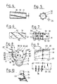
- the process for reshaping waste paper 7 into compacts 8, which form an easily manageable bulk material comprises a shredding process 1 in which the waste paper 7 is cut up and torn into small pieces.
- the shredded waste paper 7 is then transferred from a first part 4 of a conveying process, which simultaneously acts as a secondary shredding process, to a second part 2 of the conveying process, before the end of which a water addition 5 takes place under low pressure, from which the waste paper 7 is sent to a mixing machine.
- part 6 of the water additive is added immediately before or during the first part 4 of the conveying process.
- the device for carrying out the method comprises a comminution device 10 with two sets 62, 62 'of knife disks, which are arranged on two in parallel to one another Axes 57, 57 'are mounted on mutually intermeshing shafts in a shaft 58 of a housing 33, onto which a hopper 60 for the waste paper 7 is placed on top of the shredding device 10.
- a comminution device 10 with two sets 62, 62 'of knife disks, which are arranged on two in parallel to one another Axes 57, 57 'are mounted on mutually intermeshing shafts in a shaft 58 of a housing 33, onto which a hopper 60 for the waste paper 7 is placed on top of the shredding device 10.
- an intermediate conveyor 18, which is located at a short distance 19 above the conveyor part 13 of the screw 12 of the screw press 11 between two Side walls 34,34 'is rotatably mounted on one side to form a uniform gap 35,35'.
- the intermediate conveyor 18 is driven in the same direction with the worm 12, which is also mounted on one side, and is designed as a worm 21, on the bearing end of which a radial disk 24 is attached, while on the free end two radially oriented conveying paddles 27 are attached, the axial extent 28 of which is about a third the axial length 25 of the intermediate conveyor 18 occupies.
- guide parts 55 made of square profiles are arranged at intervals from one another, which are fastened to the side walls 34 and 34' and serve to promote the waste paper 7 in the axial direction, the guide parts 55 through the gap 35 and 35 'up to are guided a short distance to the circumference 38 of the intermediate conveyor 18 and support re-shredding of the waste paper 7 on the side wall 35 on which the intermediate conveyor 18 moves downwards, while the guide parts 55 on the side wall 35 'on which the intermediate conveyor 18 moves upwards, act as wipers.
- the screw press 11 arranged below the intermediate conveyor 18 has a screw 12 which is supported on one side, with its conveying part 13 in an upwardly open screw trough 14 rotates in the same direction as the intermediate conveyor 18 and at the same speed and is coiled in the same direction so that the direction of conveyance 20 coincides and the intermediate conveyor 18 supports the conveying action of the conveying part 13 of the screw 12.
- the screw 12 has at the free end a conical mixing and compression part 15, which is arranged in a conical mouthpiece 16, in which the waste paper is thoroughly mixed and strongly compressed, even before the end of the conveying part 13 in its upper region the water additive 5 is injected through a nozzle 17 under low pressure so that it is wetted and the glue bond released and reconnected in the conical mouthpiece 16.
- the shaped compacts 8 enter between the jaws 59 of an immediately adjacent pliers press 61, with which the pressing pressure of the screw press 11 is controlled and from which the compacts 8 are released into a container.
- the intermediate conveyor 18 has a screw 21, the pitch 22 of which coincides with the pitch 23 of the conveying part 13 and whose pitch 22 and depth 26 correspond to a multiple of the particle size of the shredded waste paper 7.
- the axial length 25 of the intermediate conveyor 18 corresponds approximately to the axial length of the conveyor part 13.
- Intermediate conveyor 18 and screw 12 are driven by a common drive 50 via a reduction gear 51, the intermediate conveyor 18 being coupled via a mechanical freewheel 53, so that when the screw 12 returns, the intermediate conveyor 18 is stopped due to overloading of the screw press 11 or the device 18, so that no waste paper 7, especially when moistened, can be conveyed back into the intermediate conveyor 18 and further into the space above.
- the intermediate conveyor 18 is provided with strongly axially aligned drivers 30 for processing heavily sized and compacted waste paper types, which are arranged on a core 31, the radius of which is a multiple of the aisle depth 26. This arrangement strengthens the radial conveyance and, together with secondary comminution tools 36, further comminution of the waste paper 7.
- the drivers 30 are divided into spaced partial drivers 32, the surfaces 56, 56 'of which are aligned more axially than the arrangement of the partial drivers 32 on the core 31 of the intermediate conveyor 18 in FIG. 6.
- a particularly strong secondary comminution effect is achieved with partial drivers 32, the surfaces of which are divided into two surfaces 56, 56 'with different axial orientations.
- partial drivers 32 are mounted in two rows 69, 69 'in the axial direction on the core 31 of the intermediate conveyor 18 and are rotated with their surfaces 56 against the axial direction.
- the sub-drivers 32 are successively arranged alternately offset by 90 angular degrees in the axial direction.
- the partial drivers 32 consist of two parts 70, 71, which are placed against one another and are screwed or welded onto the core 31 with fastening surfaces 71, or from a single correspondingly folded part.
- the side wall 34 on which the intermediate conveyor 18 has a conveying direction 52 in the direction of the screw 12 is provided with an opening 37 for an insert part 39, which with its re-shredding tools 36 passes through the gap 35 into recesses 40 Scope 38, that is, engages in the drivers 30 of the intermediate conveyor 18.
- the secondary shredding tools 36 are simultaneously effective over a small part 41 of the circumference 38. When using knife-shaped secondary comminution tools 36, these are in rows in the conveying direction 52 over the axial one Length 25 of the intermediate conveyor 18 spaced apart.
- the insert part 39 is screwed to the opening 37 or can be pivoted against spring force about the axis 63 and can be exchanged for insert parts 39 with other secondary comminution tools 36, for example with grinding elements in the form of plates 64.
- a nozzle 54 is screwed into the side wall 34, through which a part 6 of the water additive 5 is injected.
- the secondary comminution tools 36 consist of cutting or tearing members 65 which, inserted in a row, extend into a radial gap 68 formed by the partial drivers 32 as far as the core 31 of the intermediate conveyor 18.
- the cutting edges 73 of the cutting or tearing members 65 form a cutting angle with the partial drivers 32, which opens in the direction of the core 31.
- each cutting or tearing member 65 extends with the cutting edge 73 approximately tangentially to the circumference of the core 31, extended and covered to the outer circumference 9 of the screw 12 of the screw press 11, forming a guide, the distance to the housing wall and the screw trough 14 .
- wipers 49 are attached which bridge the gap 35' and protrude into the recess 40 on the circumference 38 of the intermediate conveyor.
- the screw trough 14 is fastened to the frame 43 of the device with a few screw connections 42 and the side walls 34, 34 ′ with a few screw connections 44 and is easily removable.
- the drive shafts 45 and 46 of the worm 12 and the intermediate conveyor 18 are arranged in a rotationally fixed manner with the worm 12 and the intermediate conveyor 18 via intermediate shafts 47 and 48, so that the changing of the worm 12 and intermediate conveyor 18 is also possible in a simple manner.
Landscapes
- Engineering & Computer Science (AREA)
- Mechanical Engineering (AREA)
- Food Science & Technology (AREA)
- Life Sciences & Earth Sciences (AREA)
- Wood Science & Technology (AREA)
- Crushing And Pulverization Processes (AREA)
- Paper (AREA)
Abstract
Claims (23)
- Procédé continu pour la fabrication de pièces moulées manipulables en papier de rebut, qui comprend une étape de déchiquetage pour la découpe en menus fragments et l'arrachement de papier de rebut, à la suite de laquelle est prévue une étape de transport qui est subdivisée en une première partie (4) qui fait suite à l'étape de déchiquetage (1) et en une seconde partie (2) pendant laquelle le papier de rebut est soumis à une étape de mélange et de compactage, avec adjonction d'eau sous pression de 5 à 20 % en poids dans le procédé, qui fait gonfler partiellement et se dégager les unes des autres les fibres du papier de rebut, une nouvelle liaison du papier de rebut pouvant être réalisée pendant l'étape de compactage qui améliore la tenue des pièces moulées après formage et après au moins une évaporation partielle de l'eau ajoutée et refroidissement, de manière à former un produit en vrac manipulable, caractérisé en ce que l'eau ajoutée (5) pendant la seconde partie (2) de l'étape de transport est ajoutée à la fin de celle-ci directement avant l'étape de mélange et de compactage (3), alors que lorsqu'il s'agit au moins d'un papier de rebut fortement mouillable, une partie (6) de l'eau ajoutée (5) est ajoutée avant ou pendant la première partie (4) de l'étape de transport, suite à quoi le papier de rebut déchiqueté est soumis à une étape de déchiquetage complémentaire.
- Procédé continu pour la fabrication de pièces moulées manipulables en papier de rebut selon la revendication 1, caractérisé en ce que l'eau ajoutée (5) et sa partie (6) qui est ajoutée pendant la première partie (4) de l'étape de transport a lieu sous une pression de 1,5 à 2,5 bars régulée et réduite par rapport à la pression de la conduite d'eau du réseau.
- Dispositif pour la mise en oeuvre du procédé selon les revendications 1 et 2, comprenant un dispositif de déchiquetage par lequel le papier de rebut est découpé et déchiqueté et dirigé vers une extrudeuse (11) avec interposition d'un convoyeur intermédiaire (18), extrudeuse dont la vis (12) qui est montée sur un côté tourne dans une auge ouverte (14) et qui comprend une partie transporteuse (13) et une partie conique de mélange et de compactage (15) dans un élément de sortie conique (16), l'eau ajoutée (5) étant pulvérisée sous pression par une buse (17) sur le papier de rebut (7) dans ce dispositif, caractérisé en ce que la buse (17) destinée à l'eau ajoutée (5) est montée directement avant l'élément de sortie (16) dans la paroi de l'auge (14) de la vis près de l'extrémité de la partie transporteuse (13) de la vis (12) de l'extrudeuse (11), une partie (6) de l'eau (5) étant ajoutée en cas de besoin par une buse (54) dans la région du convoyeur intermédiaire (18), qui est disposé entre le dispositif de déchiquetage (10) et la partie transporteuse (13) de la vis (12), le transporteur intermédiaire (18) qui forme simultanément un dispositif de déchiquetage complémentaire étant monté au-dessus de la partie transporteuse (13) de la vis (12) et parallèlement à son axe, de façon à tourner dans le même sens et de façon qu'il s'étende sensiblement sur la totalité de la longueur (29) de la partie transporteuse (13) de la vis (12).
- Dispositif selon la revendication 3, caractérisé en ce que le convoyeur intermédiaire (18) est entraîné sensiblement selon la même vitesse de rotation que la partie transporteuse (13).
- Dispositif selon la revendication 3 ou 4, caractérisé en ce que le convoyeur intermédiaire (18) est équipé d'éléments d'entraînement (30) orientés sensiblement en direction axiale sur une partie importante du transport radial du papier de rebut (7) déchiqueté.
- Dispositif selon l'une quelconque des revendications 3 à 5, caractérisé en ce que le convoyeur intermédiaire (18) est muni d'éléments d'entraînement (30) qui sont subdivisés dans leur direction axiale en éléments d'entraînement partiels (32) situés à distance les uns des autres, qui sont orientés dans la direction axiale du convoyeur intermédiaire (18), les surfaces (56) des éléments d'entraînement partiels (32) étant coudées ou disposées respectivement par sections dans des positions différentes par rapport à la direction axiale.
- Dispositif selon l'une quelconque des revendications 3 à 6, caractérisé en ce que le convoyeur intermédiaire (18) est monté dans un carter (33) qui comprend des parois latérales (34, 34') qui suivent au moins grossièrement le contour du convoyeur intermédiaire (18) et qui forment un passage (35, 35') sensiblement régulier entre les parois latérales (34 et 34') et le convoyeur intermédiaire (18).
- Dispositif selon l'une quelconque des revendications 3 à 7, caractérisé en ce que sont fixés dans le passage (35, 35') et sur les parois latérales (34, 34') plusieurs éléments de guidage (55) s'étendant en direction axiale et disposés à distance les uns des autres, constitués de préférence par des barres profilées carrées qui s'étendent au moins en partie dans le passage (35, 35').
- Dispositif selon la revendication 7 ou 8, caractérisé en ce que sont prévus des outils de déchiquetage complémentaire (36) sur la paroi latérale (34) du côté où le convoyeur intermédiaire (18) effectue un transport vers le bas en direction de la partie transporteuse (13), outils qui peuvent être montés dans une ouverture (37) de la paroi latérale (34), qui sont constitués par des organes de coupe ou d'arrachement (65) ou par des organes de broyage (64) qui coopèrent avec la périphérie (38) du convoyeur intermédiaire (18), de préférence sur la totalité de sa longueur axiale (25), et de préférence avec des contre-outils montés sur ce convoyeur intermédiaire.
- Dispositif selon l'une quelconque des revendications 7 à 9, caractérisé en ce que les outils de déchiquetage complémentaire (36) sont montés en étant rassemblés sur un élément rapporté (39).
- Dispositif selon l'une quelconque des revendications 7 à 10, caractérisé en ce que les outils de déchiquetage complémentaire (36) pénètrent dans la région externe de la périphérie (38) du convoyeur intermédiaire (18) dans des évidements (40) des éléments d'entraînement (30).
- Dispositif selon l'une quelconque des revendications 7 à 11, caractérisé en ce que les outils de déchiquetage complémentaire (36) forment avec la périphérie (38) du convoyeur intermédiaire (18) un passage réglable (35) qui est plus petit, et de préférence sensiblement plus petit, que la dimension des particules du papier de rebut (7) déchiqueté par le dispositif de déchiquetage (10).
- Dispositif selon la revendication 10, caractérisé en ce que l'élément rapporté (39) est monté sur la paroi latérale (34) à l'encontre de la force d'un ressort pour venir se dégager du passage (35) et peut être monté dans la paroi latérale (34) de préférence avec divers outils (36) de déchiquetage complémentaire pouvant être remplacés au choix.
- Dispositif selon l'une quelconque des revendications 7 à 9, caractérisé en ce que des racles (49) destinées au papier de rebut (7) sont montées sur la paroi latérale (34'), sur le côté où le convoyeur intermédiaire (18) effectue son transport vers le haut.
- Dispositif selon la revendication 3, caractérisé en ce que l'extrudeuse (11) comprend une auge (14) qui est fixée au moins par quelques boulons (42) au châssis (43) sur lequel est monté le carter (33) du convoyeur intermédiaire (18), dont les parois latérales (34, 34') sont également fixées par quelques boulons (44) au châssis (43) de manière que la vis (12) et/ou le convoyeur intermédiaire (18) soient d'accès facile.
- Dispositif selon l'une quelconque des revendications 7 à 9, ou 15, caractérisé en ce qu'une buse (54) destinée à pulvériser une partie (6) de l'eau ajoutée (5) est montée dans la paroi latérale (34) sur le côté où le convoyeur intermédiaire (18) effectue son transport en direction de la vis (12), avant ou entre les outils de déchiquetage complémentaire (36).
- Dispositif selon la revendication 1 ou 16, caractérisé en ce qu'une buse (17) destinée à pulvériser l'eau ajoutée (5) est vissée dans la paroi de l'auge (14) de la vis à proximité de l'extrémité de la partie transporteuse (16) de la vis (12), avant l'élément de sortie conique (16) et dans la région supérieure de la partie transporteuse (13).
- Dispositif selon l'une quelconque des revendications 3 à 7, 9 ou 11 à 13 ou 15 à 18, caractérisé en ce que le convoyeur intermédiaire (18) est muni d'éléments d'entraînement partiels (32) qui sont montés sur le corps (31) à distance les uns des autres en formant en direction axiale du convoyeur intermédiaire (18) un passage radial (68) pour les outils (36) de déchiquetage complémentaire sur le trajet qu'ils suivent.
- Dispositif selon la revendication 18, caractérisé en ce que les éléments d'entraînement partiels (32) sont montés sur plusieurs rangées (69, 69') orientées en direction axiale et réparties régulièrement sur le corps (31), deux rangées avec des éléments d'entraînement partiels (32) opposés les uns aux autres étant de préférence décalées alternativement en direction axiale de 90° et leurs surfaces (56) étant orientées en étant tournées en direction axiale.
- Dispositif selon la revendication 18 ou 19, caractérisé en ce que chaque élément d'entraînement partiel (32) est constitué en deux parties (70, 70'), ou constitués par un élément plié, qui est ou sont vissés ou soudés par une surface de fixation (71) qui est adaptée au corps (31).
- Dispositif selon la revendication 9, caractérisé en ce que les organes de coupe ou d'arrachement (65) s'étendent jusqu'au corps (31) alors que leurs arêtes de coupe (73) forment un angle de cisaillement avec les bords longitudinaux (72) des éléments d'entraînement partiels (32), angle qui s'ouvre en direction du corps (31).
- Dispositif selon la revendication 9 ou 21, caractérisé en ce que les organes de coupe ou d'arrachement (65) s'étendent par leur arête de coupe (73) sensiblement tangentiellement à la périphérie du corps (31) jusqu'à la périphérie externe (9) de la vis (12) de l'extrudeuse (11) et jusqu'à un faible interstice de coupe (75) qu'ils forment, et s'étendent avec la lame de coupe (74) de préférence sensiblement à travers le passage (35) ou sur la distance allant jusqu'à la paroi du carter de l'auge (14) de la vis.
- Dispositif selon la revendication 21 ou 22, caractérisé en ce que sont prévues plusieurs rangées d'organes de coupe ou d'arrachement (65) qui sont également décalées en direction du transport (52).
Priority Applications (1)
| Application Number | Priority Date | Filing Date | Title |
|---|---|---|---|
| AT88903821T ATE95858T1 (de) | 1987-05-01 | 1988-04-28 | Schneckenpresse sowie verfahren zur herstellung von handhabbaren presslingen aus abfallpapier. |
Applications Claiming Priority (2)
| Application Number | Priority Date | Filing Date | Title |
|---|---|---|---|
| DE19873714624 DE3714624A1 (de) | 1987-05-01 | 1987-05-01 | Schneckenpresse sowie verfahren zur herstellung von handhabbaren presslingen aus abfallpapier |
| DE3714624 | 1987-05-01 |
Publications (2)
| Publication Number | Publication Date |
|---|---|
| EP0335916A1 EP0335916A1 (fr) | 1989-10-11 |
| EP0335916B1 true EP0335916B1 (fr) | 1993-10-13 |
Family
ID=6326679
Family Applications (1)
| Application Number | Title | Priority Date | Filing Date |
|---|---|---|---|
| EP19880903821 Expired - Lifetime EP0335916B1 (fr) | 1987-05-01 | 1988-04-28 | Extrudeuse ainsi que procede pour la fabrication de pieces moulees manipulables en papier de rebut |
Country Status (3)
| Country | Link |
|---|---|
| EP (1) | EP0335916B1 (fr) |
| DE (2) | DE3714624A1 (fr) |
| WO (1) | WO1988008466A1 (fr) |
Families Citing this family (7)
| Publication number | Priority date | Publication date | Assignee | Title |
|---|---|---|---|---|
| WO1992001833A1 (fr) * | 1990-07-18 | 1992-02-06 | Peter John Mitchell Farley | Procede et dispositif de fabrication de produits en papier |
| US5427321A (en) * | 1992-07-03 | 1995-06-27 | Meiden Plant Engineering & Construction Co., Ltd. | Waste paper processing system |
| DE4345322C2 (de) * | 1992-07-03 | 1999-08-05 | Fuji Xerox Engineering Co Ltd | Vorrichtung zum Verdichten von zu kleinen Partikeln zerkleinertem Altpapier |
| DE4444285C2 (de) * | 1993-12-14 | 1996-11-28 | Kobe Steel Ltd | Vorrichtung zum Formen von Abfallpapier enthaltendem Fasermaterial und deren Verwendung |
| CN102304864A (zh) * | 2011-07-21 | 2012-01-04 | 博爱(中国)膨化芯材有限公司 | 一种废无尘纸回收利用工艺及其设备 |
| CN110404622A (zh) * | 2019-06-10 | 2019-11-05 | 山东省田庄煤矿有限公司 | 一种炮泥成型机 |
| CN112246327A (zh) * | 2020-09-27 | 2021-01-22 | 刘超 | 一种强度高质量轻建筑材料原材料的粉碎装置 |
Family Cites Families (4)
| Publication number | Priority date | Publication date | Assignee | Title |
|---|---|---|---|---|
| DE1813501A1 (de) * | 1967-12-22 | 1969-07-03 | Zd Transportnogo Masinostrojen | Maschine zur Aktenvernichtung im Trockenverfahren |
| JPS53113383A (en) * | 1977-03-16 | 1978-10-03 | Takeshi Hatanaka | Docuement shredder |
| US4123489A (en) * | 1977-05-17 | 1978-10-31 | Flett Development Company | Method for converting waste paper products into useful forms |
| US4657192A (en) * | 1984-06-01 | 1987-04-14 | Browning James N | Paper shredder |
-
1987
- 1987-05-01 DE DE19873714624 patent/DE3714624A1/de not_active Withdrawn
-
1988
- 1988-04-28 DE DE88903821T patent/DE3884941D1/de not_active Expired - Fee Related
- 1988-04-28 EP EP19880903821 patent/EP0335916B1/fr not_active Expired - Lifetime
- 1988-04-28 WO PCT/EP1988/000360 patent/WO1988008466A1/fr active IP Right Grant
Also Published As
| Publication number | Publication date |
|---|---|
| EP0335916A1 (fr) | 1989-10-11 |
| WO1988008466A1 (fr) | 1988-11-03 |
| DE3714624A1 (de) | 1988-11-17 |
| DE3884941D1 (de) | 1993-11-18 |
Similar Documents
| Publication | Publication Date | Title |
|---|---|---|
| DE102004033344B4 (de) | Dosierzubringer und System zum Kneten und Strangpressen eines Materials | |
| DE69608918T2 (de) | Zerkleinerungsvorrichtung | |
| DE2335385B2 (de) | Verfahren und Vorrichtung zur ölgewinnung aus gereinigten Ölfrüchten und ölsaaten | |
| EP0143414B2 (fr) | Machine à agglomérer | |
| DE2625260A1 (de) | Vorrichtung zur zerkleinerung von material, insbesondere fleischwolf | |
| EP2766160A1 (fr) | Dispositif pour préparer une matière plastique | |
| DE2053419A1 (de) | Verfahren und Vorrichtung zum Mahlen von Papierstoff | |
| EP0143415B1 (fr) | Dispositif d'agglomération à deux étapes | |
| DE1502243A1 (de) | Schneckenpresse | |
| EP0335916B1 (fr) | Extrudeuse ainsi que procede pour la fabrication de pieces moulees manipulables en papier de rebut | |
| DE102005052770A1 (de) | Verfahren zur Herstellung von mit wenigstens einem Thermoplast umhüllten Holzteilchen und nach diesem Verfahren hergestellte Mischung | |
| CH663726A5 (de) | Verfahren zur herstellung von granulaten aus einem pulvermaterial und maschine zum granulieren von pulvermaterial. | |
| DE2831321A1 (de) | Vorrichtung und verfahren zur wiedergewinnung von abfaellen aus thermoplastischem kunststoff | |
| DE1303676B (fr) | ||
| CH659405A5 (de) | Zerkleinerungsvorrichtung fuer abfall. | |
| DE2928471A1 (de) | Maschine zum zerkleinern von stueckigen gegenstaenden | |
| DE3327283A1 (de) | Arbeitsverfahren einer maschine zur entrindung von holzspaenen | |
| DE3342812A1 (de) | Vorrichtung und verfahren zur extrusion von zellulosehaltigen stoffen | |
| DE3201096C2 (de) | Schneidmühle zum Zerkleinern von Angüssen | |
| DE3228517A1 (de) | Verdichtungssystem zum zusammenpressen und verdichten von pulverisierten abfallstoffen in brennstoffwuerfel | |
| EP0358735B1 (fr) | Dispositif de decoupage de fourrage comprime au moins jusqu'a une pression de stockage | |
| DE1221048B (de) | Futterkuchenpresse | |
| EP0108262B1 (fr) | Dispositif pour le traitement de déchets | |
| DE1507991C3 (de) | Vorrichtung zum Trennen des Fleisches von harten Gewebeteilen | |
| DE69003747T2 (de) | Entnahmefräse und Transportgerät. |
Legal Events
| Date | Code | Title | Description |
|---|---|---|---|
| PUAI | Public reference made under article 153(3) epc to a published international application that has entered the european phase |
Free format text: ORIGINAL CODE: 0009012 |
|
| 17P | Request for examination filed |
Effective date: 19890420 |
|
| AK | Designated contracting states |
Kind code of ref document: A1 Designated state(s): AT BE CH DE FR GB IT LI NL SE |
|
| 17Q | First examination report despatched |
Effective date: 19911002 |
|
| GRAA | (expected) grant |
Free format text: ORIGINAL CODE: 0009210 |
|
| AK | Designated contracting states |
Kind code of ref document: B1 Designated state(s): AT BE CH DE FR GB IT LI NL SE |
|
| PG25 | Lapsed in a contracting state [announced via postgrant information from national office to epo] |
Ref country code: IT Free format text: LAPSE BECAUSE OF FAILURE TO SUBMIT A TRANSLATION OF THE DESCRIPTION OR TO PAY THE FEE WITHIN THE PRE;WARNING: LAPSES OF ITALIAN PATENTS WITH EFFECTIVE DATE BEFORE 2007 MAY HAVE OCCURRED AT ANY TIME BEFORE 2007. THE CORRECT EFFECTIVE DATE MAY BE DIFFERENT FROM THE ONE RECORDED.SCRIBED TIME-LIMIT Effective date: 19931013 Ref country code: SE Effective date: 19931013 Ref country code: NL Effective date: 19931013 |
|
| REF | Corresponds to: |
Ref document number: 95858 Country of ref document: AT Date of ref document: 19931015 Kind code of ref document: T |
|
| REF | Corresponds to: |
Ref document number: 3884941 Country of ref document: DE Date of ref document: 19931118 |
|
| ET | Fr: translation filed | ||
| GBT | Gb: translation of ep patent filed (gb section 77(6)(a)/1977) |
Effective date: 19940114 |
|
| NLV1 | Nl: lapsed or annulled due to failure to fulfill the requirements of art. 29p and 29m of the patents act | ||
| PGFP | Annual fee paid to national office [announced via postgrant information from national office to epo] |
Ref country code: BE Payment date: 19940317 Year of fee payment: 7 |
|
| PLBE | No opposition filed within time limit |
Free format text: ORIGINAL CODE: 0009261 |
|
| STAA | Information on the status of an ep patent application or granted ep patent |
Free format text: STATUS: NO OPPOSITION FILED WITHIN TIME LIMIT |
|
| 26N | No opposition filed | ||
| PG25 | Lapsed in a contracting state [announced via postgrant information from national office to epo] |
Ref country code: BE Effective date: 19950430 |
|
| BERE | Be: lapsed |
Owner name: ALOIS POTTINGER MASCHINENFABRIK G.M.B.H. Effective date: 19950430 |
|
| PGFP | Annual fee paid to national office [announced via postgrant information from national office to epo] |
Ref country code: FR Payment date: 19970411 Year of fee payment: 10 |
|
| PG25 | Lapsed in a contracting state [announced via postgrant information from national office to epo] |
Ref country code: FR Free format text: THE PATENT HAS BEEN ANNULLED BY A DECISION OF A NATIONAL AUTHORITY Effective date: 19980430 |
|
| REG | Reference to a national code |
Ref country code: FR Ref legal event code: ST |
|
| PGFP | Annual fee paid to national office [announced via postgrant information from national office to epo] |
Ref country code: GB Payment date: 20000418 Year of fee payment: 13 |
|
| PG25 | Lapsed in a contracting state [announced via postgrant information from national office to epo] |
Ref country code: GB Free format text: LAPSE BECAUSE OF NON-PAYMENT OF DUE FEES Effective date: 20010428 |
|
| GBPC | Gb: european patent ceased through non-payment of renewal fee |
Effective date: 20010428 |
|
| PGFP | Annual fee paid to national office [announced via postgrant information from national office to epo] |
Ref country code: AT Payment date: 20030324 Year of fee payment: 16 |
|
| PGFP | Annual fee paid to national office [announced via postgrant information from national office to epo] |
Ref country code: DE Payment date: 20030326 Year of fee payment: 16 |
|
| PGFP | Annual fee paid to national office [announced via postgrant information from national office to epo] |
Ref country code: CH Payment date: 20030725 Year of fee payment: 16 |
|
| PG25 | Lapsed in a contracting state [announced via postgrant information from national office to epo] |
Ref country code: AT Free format text: LAPSE BECAUSE OF NON-PAYMENT OF DUE FEES Effective date: 20040428 |
|
| PG25 | Lapsed in a contracting state [announced via postgrant information from national office to epo] |
Ref country code: CH Free format text: LAPSE BECAUSE OF NON-PAYMENT OF DUE FEES Effective date: 20040430 Ref country code: LI Free format text: LAPSE BECAUSE OF NON-PAYMENT OF DUE FEES Effective date: 20040430 |
|
| PG25 | Lapsed in a contracting state [announced via postgrant information from national office to epo] |
Ref country code: DE Free format text: LAPSE BECAUSE OF NON-PAYMENT OF DUE FEES Effective date: 20041103 |
|
| REG | Reference to a national code |
Ref country code: CH Ref legal event code: PL |