EP0335718B1 - Verfahren zur Herstellung einer Reifenverstärkung - Google Patents
Verfahren zur Herstellung einer Reifenverstärkung Download PDFInfo
- Publication number
- EP0335718B1 EP0335718B1 EP89303156A EP89303156A EP0335718B1 EP 0335718 B1 EP0335718 B1 EP 0335718B1 EP 89303156 A EP89303156 A EP 89303156A EP 89303156 A EP89303156 A EP 89303156A EP 0335718 B1 EP0335718 B1 EP 0335718B1
- Authority
- EP
- European Patent Office
- Prior art keywords
- cords
- guide plate
- movable guide
- rubber sheets
- rolls
- Prior art date
- Legal status (The legal status is an assumption and is not a legal conclusion. Google has not performed a legal analysis and makes no representation as to the accuracy of the status listed.)
- Expired - Lifetime
Links
- 238000000034 method Methods 0.000 title claims description 28
- 230000003014 reinforcing effect Effects 0.000 title claims description 24
- 238000003825 pressing Methods 0.000 claims description 24
- 239000000835 fiber Substances 0.000 claims description 17
- 238000004804 winding Methods 0.000 claims description 15
- 239000000126 substance Substances 0.000 claims description 9
- 238000011144 upstream manufacturing Methods 0.000 claims description 9
- 238000010073 coating (rubber) Methods 0.000 claims description 4
- 229920000271 Kevlar® Polymers 0.000 description 5
- 239000004761 kevlar Substances 0.000 description 5
- 238000004519 manufacturing process Methods 0.000 description 4
- 238000009434 installation Methods 0.000 description 3
- 239000004033 plastic Substances 0.000 description 3
- 238000000926 separation method Methods 0.000 description 3
- 230000009471 action Effects 0.000 description 2
- 230000008859 change Effects 0.000 description 2
- 238000010276 construction Methods 0.000 description 2
- 239000011295 pitch Substances 0.000 description 2
- 230000002035 prolonged effect Effects 0.000 description 2
- 229910000831 Steel Inorganic materials 0.000 description 1
- 239000011248 coating agent Substances 0.000 description 1
- 238000000576 coating method Methods 0.000 description 1
- 239000004744 fabric Substances 0.000 description 1
- 230000005484 gravity Effects 0.000 description 1
- 230000006872 improvement Effects 0.000 description 1
- 230000004048 modification Effects 0.000 description 1
- 238000012986 modification Methods 0.000 description 1
- 238000004080 punching Methods 0.000 description 1
- 230000009467 reduction Effects 0.000 description 1
- 230000000717 retained effect Effects 0.000 description 1
- 239000010959 steel Substances 0.000 description 1
Images

Classifications
-
- B—PERFORMING OPERATIONS; TRANSPORTING
- B32—LAYERED PRODUCTS
- B32B—LAYERED PRODUCTS, i.e. PRODUCTS BUILT-UP OF STRATA OF FLAT OR NON-FLAT, e.g. CELLULAR OR HONEYCOMB, FORM
- B32B37/00—Methods or apparatus for laminating, e.g. by curing or by ultrasonic bonding
- B32B37/14—Methods or apparatus for laminating, e.g. by curing or by ultrasonic bonding characterised by the properties of the layers
- B32B37/16—Methods or apparatus for laminating, e.g. by curing or by ultrasonic bonding characterised by the properties of the layers with all layers existing as coherent layers before laminating
- B32B37/20—Methods or apparatus for laminating, e.g. by curing or by ultrasonic bonding characterised by the properties of the layers with all layers existing as coherent layers before laminating involving the assembly of continuous webs only
- B32B37/203—One or more of the layers being plastic
- B32B37/206—Laminating a continuous layer between two continuous plastic layers
-
- B—PERFORMING OPERATIONS; TRANSPORTING
- B29—WORKING OF PLASTICS; WORKING OF SUBSTANCES IN A PLASTIC STATE IN GENERAL
- B29C—SHAPING OR JOINING OF PLASTICS; SHAPING OF MATERIAL IN A PLASTIC STATE, NOT OTHERWISE PROVIDED FOR; AFTER-TREATMENT OF THE SHAPED PRODUCTS, e.g. REPAIRING
- B29C70/00—Shaping composites, i.e. plastics material comprising reinforcements, fillers or preformed parts, e.g. inserts
- B29C70/04—Shaping composites, i.e. plastics material comprising reinforcements, fillers or preformed parts, e.g. inserts comprising reinforcements only, e.g. self-reinforcing plastics
- B29C70/06—Fibrous reinforcements only
- B29C70/10—Fibrous reinforcements only characterised by the structure of fibrous reinforcements, e.g. hollow fibres
- B29C70/16—Fibrous reinforcements only characterised by the structure of fibrous reinforcements, e.g. hollow fibres using fibres of substantial or continuous length
- B29C70/20—Fibrous reinforcements only characterised by the structure of fibrous reinforcements, e.g. hollow fibres using fibres of substantial or continuous length oriented in a single direction, e.g. roofing or other parallel fibres
-
- B—PERFORMING OPERATIONS; TRANSPORTING
- B29—WORKING OF PLASTICS; WORKING OF SUBSTANCES IN A PLASTIC STATE IN GENERAL
- B29D—PRODUCING PARTICULAR ARTICLES FROM PLASTICS OR FROM SUBSTANCES IN A PLASTIC STATE
- B29D30/00—Producing pneumatic or solid tyres or parts thereof
- B29D30/06—Pneumatic tyres or parts thereof (e.g. produced by casting, moulding, compression moulding, injection moulding, centrifugal casting)
- B29D30/38—Textile inserts, e.g. cord or canvas layers, for tyres; Treatment of inserts prior to building the tyre
-
- B—PERFORMING OPERATIONS; TRANSPORTING
- B32—LAYERED PRODUCTS
- B32B—LAYERED PRODUCTS, i.e. PRODUCTS BUILT-UP OF STRATA OF FLAT OR NON-FLAT, e.g. CELLULAR OR HONEYCOMB, FORM
- B32B38/00—Ancillary operations in connection with laminating processes
- B32B38/0012—Mechanical treatment, e.g. roughening, deforming, stretching
-
- B—PERFORMING OPERATIONS; TRANSPORTING
- B29—WORKING OF PLASTICS; WORKING OF SUBSTANCES IN A PLASTIC STATE IN GENERAL
- B29K—INDEXING SCHEME ASSOCIATED WITH SUBCLASSES B29B, B29C OR B29D, RELATING TO MOULDING MATERIALS OR TO MATERIALS FOR MOULDS, REINFORCEMENTS, FILLERS OR PREFORMED PARTS, e.g. INSERTS
- B29K2021/00—Use of unspecified rubbers as moulding material
-
- B—PERFORMING OPERATIONS; TRANSPORTING
- B29—WORKING OF PLASTICS; WORKING OF SUBSTANCES IN A PLASTIC STATE IN GENERAL
- B29K—INDEXING SCHEME ASSOCIATED WITH SUBCLASSES B29B, B29C OR B29D, RELATING TO MOULDING MATERIALS OR TO MATERIALS FOR MOULDS, REINFORCEMENTS, FILLERS OR PREFORMED PARTS, e.g. INSERTS
- B29K2105/00—Condition, form or state of moulded material or of the material to be shaped
- B29K2105/06—Condition, form or state of moulded material or of the material to be shaped containing reinforcements, fillers or inserts
- B29K2105/08—Condition, form or state of moulded material or of the material to be shaped containing reinforcements, fillers or inserts of continuous length, e.g. cords, rovings, mats, fabrics, strands or yarns
- B29K2105/10—Cords, strands or rovings, e.g. oriented cords, strands or rovings
- B29K2105/101—Oriented
-
- B—PERFORMING OPERATIONS; TRANSPORTING
- B29—WORKING OF PLASTICS; WORKING OF SUBSTANCES IN A PLASTIC STATE IN GENERAL
- B29K—INDEXING SCHEME ASSOCIATED WITH SUBCLASSES B29B, B29C OR B29D, RELATING TO MOULDING MATERIALS OR TO MATERIALS FOR MOULDS, REINFORCEMENTS, FILLERS OR PREFORMED PARTS, e.g. INSERTS
- B29K2105/00—Condition, form or state of moulded material or of the material to be shaped
- B29K2105/24—Condition, form or state of moulded material or of the material to be shaped crosslinked or vulcanised
- B29K2105/246—Uncured, e.g. green
-
- B—PERFORMING OPERATIONS; TRANSPORTING
- B29—WORKING OF PLASTICS; WORKING OF SUBSTANCES IN A PLASTIC STATE IN GENERAL
- B29L—INDEXING SCHEME ASSOCIATED WITH SUBCLASS B29C, RELATING TO PARTICULAR ARTICLES
- B29L2030/00—Pneumatic or solid tyres or parts thereof
- B29L2030/003—Plies; Breakers
Definitions
- This invention relates to a method of producing reinforcing members to be used in tires and having elongations which do not detrimentally affect tire performance and enable stresses to be uniformly distributed in width directions without any stress concentration.
- Rubber members having cords embedded therein have been widely used as elastic members having cut-resistant property in various fields.
- elastic members When such elastic members are used in structures subjected to various external forces such as tires, in addition to the cut-resistant property they are required to have elongations to an extent such that they do not affect the tire performance.
- a first example is a spiral stripe method disclosed in Japanese Patent Application Laid-open No. 47-13,684.
- stripes 01 are embraced between rubber-like elastic members 02 and 03 and embedded therein.
- they are caused to pass through a fixed pattern plate 05 and working pattern plates 04 moved along orbits of circular arcs, so that the stripes 01 are permanently spirally set or deformed.
- Fig. 2 As second example shown in Fig. 2 is a gear setting method disclosed in Japanese Patent Application Laid-open No. 52-91,967.
- One fiber web 012 is transferred in its longitudinal direction by a chain conveyor 017.
- a plurality of fiber yarns 011 are supplied onto an upper surface of the chain conveyor 017 with substantially equal intervals in its width directions.
- a pair of gear-shaped rollers 014 and 015 are used, which are formed on their outer circumferences with a plurality of crests and valleys.
- Fiber stripes 011 are supplied from a creel 010 and passed through the rollers 014 and 015 immediately before they arrive onto the upper surface of the web 012 so that the stripes 011 are shaped into wave-forms with substantially equal pitches in their lengthwise direction.
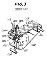
- a third example shown in Fig. 3 is a zigzag belt method disclosed in Japanese Patent Application Laid-open No. 61-502,877.
- a flexible endless belt 022 extends about cylindrical members 020 and 021.
- Coated continuous cord reinforcing stripes 023 in the form of waves are shaped in wave-forms on the endless belt 022.
- the continuous cord reinforcing stripes 023 are supplied through suitably shaped grooves in matching means 024 and between rollers 025 and 026 rotating in opposite directions and forcing the stripes 023 against the endless belt 022.
- the matching means 024 is connected through control belts 028 to a support 027 reciprocatively driven by means of a cylindrical cam device 026.
- the cord reinforcing stripes 023 are thus supplied onto the endless belt 022 in the zigzag patterns over the width of the endless belt 022.
- stripes susceptible to plastic deformation such as steel cords can be easily permanently set into wave-forms.
- these methods could not be used for soft cords such as chemical fibers because they are difficult to be permanently set.
- the coated cord reinforcing stripes are used so that an apparatus for coating the cords is needed.
- such coated cords are arranged one upon the other so that the air is likely to be accumulated between the cords.
- the number of the coated cords arranged on the endless belt during one operation cycle is so limited that production efficiency remains at low value.
- the present invention provides a method of producing a tire reinforcing member comprising the steps of paying off chemical fiber cords from bobbins to pass through respective small apertures of a guide plate to arrange them in a predetermined positional relation, passing the cords over winding type braking means including winding rolls each having an outer surface coated with rubber, diverting the cords about a dancer roller, causing the cords to pass in parallel through respective small apertures of a movable guide plate reciprocated in horizontal directions perpendicular to the advancing direction of the cords, feeding the cords reciprocatively moved by the movable guide plate to pressing rolls of a calender for rubber coating, provided closely adjacent the movable guide plate, sandwiching the cords in the form of waves without overlapping the cords between two rubber sheets, and pressing the rubber sheets to each other to embed the cords into the rubber sheets and adhere closed surfaces of the rubber sheets to be integrated, thereby obtaining the tire reinforcing member.
- cords snugly arranged by the guide plates are fed through the winding type braking means and the dancer roller and caused to pass through the small apertures of the movable guide plate. Therefore, the cords upstream of the movable guide plate are maintained under a predetermined tensile force with the aid of the winding type braking means. Moreover, any slack in the cords caused by the reciprocative movements of the movable guide plate is taken up by the dancer roller so that cords are uniformly moved together under the uniform tensile force to the movable guide plate. Therefore, the cords are always stably supplied in this manner.
- the cords passed through the movable plate are fed to the calender for rubber coating arranged closely adjacent the movable guide plate. Accordingly, the respective cords are under the predetermined tensile force and sandwiched between and coated with the rubber sheets, while forming wave-forms.
- the method according to the invention is applicable to chemical fiber cords not susceptible to plastic deformation.
- Shapes of the wave-forms of the cords are readily modified by changing traverse distances of the movable guide plate and relative speeds between rotating speed of the calender and reciprocative moving speed of the movable guide plate.
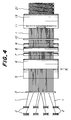
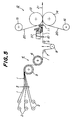
- FIG. 4 is a plan view of an apparatus to be used for carrying out the method according to the invention and Fig. 5 is a side view thereof.
- a plurality of bobbins 2 are arranged upstream (left side viewed in Fig. 4 or 5) of proceeding lines of cords 1 wound about the bobbins 2.
- the cords are Kevlar cords of high strength chemical fibers.
- Kevlar is a high strength chemical fiber which is soft but does not undergo plastic-deformation and exhibits very small elongation when being subjected to a load.
- the cords 1 paid off the bobbins 2 are drawn to a guide plate 3 and pass through a plurality of small apertures formed at predetermined positions of the guide plate 3.
- the cords 1 passed through the guide plate 3 are then wound about winding rolls 5 and 6 of a winding type braking means 4.
- the winding rolls 5 and 6 are so constructed that the cords 1 extend about the upstream winding roll 5 over approximately a quarter of a circumference of the roll 5 in a clockwise direction and then extend about the downstream winding roll 6 over approximately a quarter of a circumference of the roll 6 in a counterclockwise direction and are fed to a next station.
- the cords 1 are retained in a predetermined positional relation between them by means of the guide plate 3 so that the cords 1 are snugly arranged in the same plane in parallel with each other with equal intervals when the cords extend about the winding roll 5.
- the winding rolls 5 and 6 have large diameters and have large friction because their surfaces are coated with rubber. Therefore, lengths of the cords contacting the rolls are relatively long and coefficients of friction are comparatively large. As a result, the cords 1 are prevented from slipping so that tensile forces in the cords on the downstream side can be sufficiently maintained.
- the cords 1 After passing the winding roll 6, the cords 1 extend about a fixed roller 7 from above in the clockwise direction. Thereafter, the cords 1 extend about a dancer roller 8 over a lower half of its circumference in the counterclockwise direction and further extend about a fixed roller 9 downstream of the dancer roller 8 in the clockwise direction. In this case, the dancer roller 8 is hung between the fixed rollers 7 and 9.
- the cords 1 are always forced downward by the dancer roller 8 by its gravity, so that upward and downward movements of the dancer roller 8 take up slack in the cords 1.
- the cords 1 paid off the fixed roller 9 pass through small apertures of a guide plate 10 and then through small apertures of a movable guide plate 11, respectively.
- the movable guide plate 11 is reciprocatively movable in a horizontal direction perpendicular to moving directions of the cords 1 so that the cords 1 upstream of the movable guide plate 11 are moved in a horizontal plane. Slack in the cords 1 which may occur in such a horizontal swinging motion of the cords 1 is taken up by the dancer roller 8 as above described.
- a calender 12 is arranged downstream of the movable guide plate 11.
- the calender 12 comprises upper and lower pressing rolls 13 and 14, and a pair of upper and lower feeding rolls 15 and 16 for supplying rubber sheets 20 between the pressing rolls 13 and 14.
- the cords 1 are sandwiched between upper and lower rubber sheets 20 fed from the feeding rolls 15 and 16 and pressed with pressure uniform in width directions so that the upper and lower rubber sheets 20 are integrally attached to each other to complete a tire reinforcing member 21.
- the movable guide plate 11 and the pressing portions of the upper and lower pressing rolls 13 and 14 are so closely adjacent each other that the cords 1 snugly arranged in a horizontal plane by means of the movable guide plate 11 are sandwiched between the rubber sheets 20, while the snugly arranged state is maintained.
- Vibration of the cords 1 on the upstream side of the movable guide plate 11 which may be caused by the reciprocative movement of the movable guide plate 11 is prevented by the guide plate 10 upstream of the movable guide plate 11.
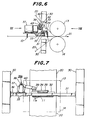
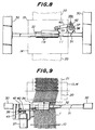
- the movable guide plate 11 is reciprocatively moved with a selected predetermined period. Driving means for the reciprocative movement of the movable guide plate 11 will be explained by referring to Figs. 6-9.
- a horizontal support frame 31 is supported by support columns 30.
- a rail 32 is provided extending in horizontal directions on an upper surface of the horizontal support frame 31 along its center.
- a slide member 33 is slidably fitted on the rail 32.
- a support plate 34 having an L-shaped cross-section is fixed to the slide member 33 with an inner surface of a horizontal web of the support plate 34 being fixed to the slide member 33.
- An upper portion of the movable guide plate 11 long in width direction is fixed to and hung from an outer surface of a vertical web of the support plate 34 being bent downward on the downstream side.
- the movable guide plate 11 is formed along its lower edge with a plurality of small apertures 11a arranged in a row which are located below a lower edge of the horizontal support frame 31.
- a horizontal base plate 36 extending toward the upstream side is provided on a bracket 35 supported on the horizontal support frame 31 on the left side viewed from the upstream side (Fig. 7).
- a motor 37 having a driving shaft 37a extending toward the downstream side.
- a crank 38 is fitted on the driving shaft 37a of the motor 37 and formed with an elongate aperture 38a which is long in a centrifugal direction.
- a bearing member 39 is provided on the support plate 34 on a side near to the motor 37.
- One end of a connecting rod 40 is pivotally connected to the crank 38 and the other end is pivotally connected to the bearing member 39.
- a bearing (not shown) whose outer race is fitted to the connecting rod 40 and whose inner race is fixed in the elongate aperture 38a of the crank 38 by means of a bolt 42 passing through the elongate aperture 38a and a nut 43 threadedly engaged with the bolt 42.
- the pivotal portion of the connecting rod 40 to the crank 38 is thus positionally adjustable to any position along the elongate aperture 38a in the centrifugal direction.
- the driving means for the movable guide plate 11 is constructed as above described.
- the motor 37 is energized to rotate the crank 38, the movable guide plate 11 is reciprocatively moved together with the slide member 33 and the support plate 34 by means of the connecting rod 40 pivotally connected to the crank 38.
- the traverse distance of the movable guide plate 11 is simply changed by changing the pivotal position of the connecting rod 40 to the crank 38.
- the cords 1 leaving she movable guide plate 11 reciprocatively moved are sandwiched and pressed between the rubber sheets 20 supplied from above and below at the pressing position of the pressing rolls 13 and 14.
- the cords 1 passed through the movable guide plate 11 are pulled at the pressing position of the pressing rolls 13 and 14 so that the cords 1 extend linearly in parallel with each other between the movable guide plate 11 and the pressing rolls 13 and 14.
- the cords 1 are reciprocatively moved in the width directions of the rubber sheets 20 by the action of the movable guide plate 11. Therefore, positions of the cords 1 in the width directions at the pressing position are varied as a function of time, with the result that the cords 1 are shaped in wave-forms sandwiched by the rubber sheets 20 downstream of the pressing position.
- the movable guide plate 11 is so positioned immediately before the pressing position of the pressing rolls 13 and 14 for the rubber sheets 20 that the distance between the movable guide plate 11 and the pressing position is as short as possible to prevent any slack in the cords 1. Accordingly, it is possible to form uniform waves of the cords 1 embedded in the tire reinforcing member 21.
- slack may tend to occur, it can be prevented by rotating the bobbins 2 in rewinding directions as the case may be.
- Amplitude of wave-forms of the cords 1 is determined by the traverse distance of the movable guide plate 11. Therefore, change in amplitude of the wave-forms can be accomplished by changing the pivotal positions of the connecting rod 40 to the crank 38. On the other hand, the wave length can be readily changed by changing relative speeds between the rotating speeds of the pressing rolls 13 and 14 and the crank 38.
- the apparatus for carrying out the method according to the invention can provide reinforcing members having most suitably wave-shaped cords embedded therein for various kinds of tires only with the one apparatus. Accordingly, the method of the invention is superior in flexibility for meeting requirements in wide ranges.
- the wave-forms of the cords 1 embedded in tire reinforcing members 21 are regular in width directions and uniform in shape. Accordingly, limiting design of construction of the tire is acceptable so that light weight and inexpensive tires can be obtained.
- the forming of the waves of cords according to the invention is effected under the same physical conditions over the entire width of the reinforcing member, so that stress concentration is prevented and the life span of the tire may also be prolonged.
- the forming of the waves of cords is accomplished by changing embracing positions between the pressing rolls 13 and 14 so that previous permanent set of the cords 1 is not needed. Therefore, it is possible to use chemical fibers such as Kevlar which are difficult to be deformed so that the tire can be made light in weight.
- the wave-forms of the cords 1 are formed on the same horizontal plane without overlapping of the cords so that air does not accumulate at overlapping portions. Therefore, damage to a tire due to separation of rubber sheets is completely prevented, which is caused by accumulated air.
- production efficiency can be raised by adopting four-calenders and the like having functions of long bobbins and rubber sheets.
- the production efficiency is high relative to investment in installation, thereby enabling cost of tire to be lowered.
- chemical fibers such as Kevlar which do not do plastic deformation can be used and therefore obtain light weight tires.
- rigidities of wave-formed cords and rubber sheets can be properly set according to the invention so that improvement of various performances of tires is expected.
- a plurality of cords are arranged in the same plane to be embedded in the rubber sheets without overlapping so that reinforcing members having uniform thicknesses are formed. Therefore, there are very few reinforcing members deviating from predetermined thicknesses and separation of rubber sheets due to accumulated air can be prevented.
Landscapes
- Engineering & Computer Science (AREA)
- Mechanical Engineering (AREA)
- Textile Engineering (AREA)
- Chemical & Material Sciences (AREA)
- Composite Materials (AREA)
- Moulding By Coating Moulds (AREA)
- Laminated Bodies (AREA)
- Tyre Moulding (AREA)
- Reinforced Plastic Materials (AREA)
Claims (5)
- Verfahren zur Herstellung eines Reifenverstärkungselements, wobei das Verfahren die Schritte aufweist, bei denen Cordfäden (1) aus einer chemischen Faser von Spulen (2) ablaufen und durch jeweilige kleine Öffnungen einer Führungsplatte (3) hindurchgeführt werden, um sie in einer vorgegebenen gegenseitigen Position anzuordnen, die Cordfäden über Bremsmittel (4) vom Wickeltyp laufen, die Wickelrollen (5, 6) umfassen, von denen jede eine mit Gummi beschichtete, äußere Oberfläche hat, die Cordfäden um eine Tänzerrolle (8) abgelenkt werden, die Cordfäden parallel durch jeweilige kleine Öffnungen (11a) einer verschiebbaren führungsplatte (11) geführt werden, die in horizontalen Richtungen senkrecht zu der Laufrichtung der Cordfäden hin- und herbewegt wird, die durch die verschiebbare Führungsplatte (11) hin- und herbewegten Cordfäden zum Beschichten mit Gummi Druckwalzen (13, 14) eines Kalanders (12), die nahe bei der verschiebbaren Führungsplatte (11) vorgesehen sind, zugeführt werden, die Cordfäden in Form von Wellen sandwichartig zwischen den zwei Gummifolien (20) angeordnet werden, ohne daß sich die Cordfäden überlappen, und die Gummifolien aufeinander gepreßt werden, um die Cordfäden in die Gummifolien einzubetten und zu bewirken, daß die aufeinander liegenden Oberflächen der zu verbindenden Gummifolien aneinander haften, wodurch das Reifenverstärkungselement (21) erhalten wird.
- Verfahren gemäß Anspruch 1, wobei die Tänzerrolle (8) über die Cordfäden (1) an zwei festen Rollen (7, 9), die stromaufwärts und stromabwärts von der Tänzerrolle (8) angeordnet sind, aufgehängt ist, um die Cordfäden durch das Gewicht der Tänzerrolle nach unten zu ziehen, wodurch der Durchhang bei den Cordfäden aufgenommen wird.
- Verfahren gemäß Anspruch 1 oder 2, wobei der Kalander (12) eine obere und eine untere Druckwalze (13, 14) aufweist, und eine obere und eine untere Zuführungswalze (15, 16) aufweist, um die Gummifolien (20) zwischen den Druckwalzen (13, 14) zuzuführen, wobei die Cordfäden (1) zwischen den von der oberen und der unteren Zuführungswalze (15, 16) zugeführten Gummifolien (20) zugeführt werden.
- Verfahren gemäß irgendeinem vorhergehenden Anspruch, wobei die Amplitude der Wellen der Cordfäden dadurch verändert wird, daß der Querhub der verschiebbaren Führungsplatte (11) geändert wird.
- Verfahren gemäß irgendeinem vorhergehenden Anspruch, wobei die Länge der Wellen der Cordfäden dadurch geändert wird, daß das Verhältnis der Rotationsgeschwindigkeit des Kalanders (12) zu der Geschwindigkeit der Hinund Herbewegung der verschiebbaren Führungsplatte (11) geändert wird.
Applications Claiming Priority (2)
| Application Number | Priority Date | Filing Date | Title |
|---|---|---|---|
| JP63074460A JP2532913B2 (ja) | 1988-03-30 | 1988-03-30 | タイヤ用補強部材の製造方法 |
| JP74460/88 | 1988-03-30 |
Publications (3)
| Publication Number | Publication Date |
|---|---|
| EP0335718A2 EP0335718A2 (de) | 1989-10-04 |
| EP0335718A3 EP0335718A3 (de) | 1991-07-10 |
| EP0335718B1 true EP0335718B1 (de) | 1997-10-15 |
Family
ID=13547886
Family Applications (1)
| Application Number | Title | Priority Date | Filing Date |
|---|---|---|---|
| EP89303156A Expired - Lifetime EP0335718B1 (de) | 1988-03-30 | 1989-03-30 | Verfahren zur Herstellung einer Reifenverstärkung |
Country Status (3)
| Country | Link |
|---|---|
| US (1) | US5002621A (de) |
| EP (1) | EP0335718B1 (de) |
| JP (1) | JP2532913B2 (de) |
Families Citing this family (26)
| Publication number | Priority date | Publication date | Assignee | Title |
|---|---|---|---|---|
| FR2668178B1 (fr) * | 1990-10-22 | 1992-12-24 | Michelin & Cie | Procede de dispositif pour appliquer des fils sur un support utilisant un tambour avec des rangees de dents fixes et mobiles, nappe obtenue et article comportant une telle nappe (pneu). |
| IT1241332B (it) * | 1990-12-04 | 1994-01-10 | Firestone Int Dev Spa | Metodo per la realizzazione di un componente armato di una carcassa di pneumatico di veicolo |
| FR2671308B1 (fr) * | 1991-01-04 | 1993-03-12 | Michelin & Cie | Procede et dispositif pour appliquer plusieurs fils sur un support a l'aide de dents flexibles; nappe obtenue et article comportant au moins une nappe : enveloppe pneumatique. |
| FR2729976A1 (fr) * | 1995-02-01 | 1996-08-02 | Michelin & Cie | Procede et dispositif pour appliquer un fil sur un support |
| US5705007A (en) * | 1995-12-21 | 1998-01-06 | Bridgestone Corporation | Method for forming cord-reinforced elastomeric stripe |
| NL1014995C2 (nl) * | 2000-04-20 | 2001-10-24 | Beiler Beheer Bv | Werkwijze en inrichting voor het vormen van een langsvezelbaan. |
| AU2003233240A1 (en) * | 2002-05-29 | 2003-12-12 | Michelin Recherche Et Technique S.A. | Device and method for applying a strip to a rotary surface |
| US20040154727A1 (en) * | 2003-02-11 | 2004-08-12 | Weissert James Thomas | Method and apparatus for manufacturing carcass plies for a tire |
| FR2882535B1 (fr) * | 2005-02-28 | 2007-04-13 | Michelin Soc Tech | Dispositif et procede de fabrication de nappes ondulees |
| US20070125471A1 (en) * | 2005-12-01 | 2007-06-07 | Weissert James T | Split cord geodesic configurations for a tire |
| US7753098B2 (en) * | 2005-12-01 | 2010-07-13 | The Goodyear Tire & Rubber Company | Spring loaded tooling head and method for tire cord application |
| US20070125478A1 (en) * | 2005-12-01 | 2007-06-07 | Weissert James T | Tire cord application station and method |
| US7740039B2 (en) * | 2005-12-01 | 2010-06-22 | The Goodyear Tire & Rubber Company | Cord cutting mechanism and method for a tire cord applicator head |
| US7686053B2 (en) * | 2005-12-01 | 2010-03-30 | The Goodyear Tire & Rubber Company | Cord tensioning and feed mechanism for a tire cord applicator head |
| US20070125480A1 (en) * | 2005-12-01 | 2007-06-07 | Henthorne David A | Synchronous drive and method for tire cord application |
| US20070125482A1 (en) * | 2005-12-01 | 2007-06-07 | Weissert James T | Bi-directional tooling head and method for tire cord application |
| JP4917804B2 (ja) * | 2005-12-28 | 2012-04-18 | 金井 宏彰 | タイヤ用ゴムシ−ト |
| US8578994B2 (en) * | 2006-12-19 | 2013-11-12 | The Goodyear Tire & Rubber Company | Applicator head for tire cord construction |
| JP5858724B2 (ja) * | 2011-10-21 | 2016-02-10 | キヤノン株式会社 | 搬送装置 |
| FR3022833B1 (fr) * | 2014-06-30 | 2017-03-10 | Michelin & Cie | Dispositif et procede pour la preparation d'une bandelette de renforcement destinee a la fabrication de pneumatiques |
| EP3124196B1 (de) * | 2015-07-28 | 2019-12-18 | Comerc International S.R.L. | Stahlseilaufbringungsvorrichtung, vorrichtung und verfahren zur stahlseilgummibeschichtung |
| US10596746B1 (en) * | 2016-03-11 | 2020-03-24 | R. H. Tamlyn & Sons | House wrap and method of manufacture |
| JP6935726B2 (ja) * | 2017-11-02 | 2021-09-15 | 住友ゴム工業株式会社 | 識別糸付着位置の制御装置 |
| CN113524749A (zh) * | 2021-07-02 | 2021-10-22 | 中策橡胶(建德)有限公司 | 一种轮胎均匀性、动平衡提升的新型胎面接头生产装置 |
| US12417526B2 (en) | 2023-03-10 | 2025-09-16 | Honeywell International Inc. | Measurement of textile cord count for rubber sheet calendering |
| CN119658993A (zh) * | 2024-12-31 | 2025-03-21 | 季华实验室 | 一种玻纤带束成型装置及其控制方法 |
Family Cites Families (18)
| Publication number | Priority date | Publication date | Assignee | Title |
|---|---|---|---|---|
| FR406038A (fr) * | 1908-08-25 | 1910-01-20 | Georges Van Der Haeghen | Revolver automatique |
| US1800179A (en) * | 1928-02-06 | 1931-04-07 | Goodyear Tire & Rubber | Reenforced web |
| GB770037A (en) * | 1954-02-13 | 1957-03-13 | Dunlop Rubber Co | Apparatus for tensioning filamentary material |
| GB964102A (en) * | 1959-10-08 | 1964-07-15 | Arthur Tunnicliffe & Son Ltd | Improvements in or relating to textile winding machines |
| NL291477A (de) * | 1962-04-16 | 1900-01-01 | ||
| USB372753I5 (de) * | 1965-04-30 | 1900-01-01 | ||
| AT259094B (de) * | 1965-07-13 | 1967-12-27 | Micafil Ag | Haftrolle für Drahtabroller mit Drahtrille |
| US3511739A (en) * | 1967-07-31 | 1970-05-12 | Friedrich Hebberling | Array of reinforcing strands for reinforced sheet material |
| US3700012A (en) * | 1971-01-07 | 1972-10-24 | Steelastic Co | Apparatus for producing helically formed filaments |
| US3941637A (en) * | 1972-11-09 | 1976-03-02 | Mitsubishi Belting Limited | Method of manufacturing a conveyor belt and an apparatus therefor |
| GB1547773A (en) * | 1975-06-05 | 1979-06-27 | Bekaert Sa Nv | Reinforcement of resilient articles |
| JPS5291967A (en) * | 1976-01-23 | 1977-08-02 | Shigemasa Takagi | Reinforcementtcontaining unwoven fabric and its manufacture |
| US4452837A (en) * | 1979-06-11 | 1984-06-05 | H. B. Fuller Company | Web reinforced with string-type adhesive and method of manufacturing same |
| DE3108140A1 (de) * | 1981-03-04 | 1982-09-16 | Continental Gummi-Werke Ag, 3000 Hannover | "fahrzeugluftreifen" |
| US4600456A (en) * | 1984-08-02 | 1986-07-15 | Armstrong Rubber Company | Method and apparatus for forming woven endless tire reinforcing belts |
| US4770290A (en) * | 1985-08-26 | 1988-09-13 | The B. F. Goodrich Company | Conveyor belt |
| US4769202A (en) * | 1985-11-29 | 1988-09-06 | The B. F. Goodrich Company | Process of making a conveyor belt |
| JPH0777766B2 (ja) * | 1987-04-21 | 1995-08-23 | 株式会社ブリヂストン | タイヤ構成部材の巻付け方法および装置 |
-
1988
- 1988-03-30 JP JP63074460A patent/JP2532913B2/ja not_active Expired - Lifetime
-
1989
- 1989-03-28 US US07/329,906 patent/US5002621A/en not_active Expired - Lifetime
- 1989-03-30 EP EP89303156A patent/EP0335718B1/de not_active Expired - Lifetime
Also Published As
| Publication number | Publication date |
|---|---|
| EP0335718A3 (de) | 1991-07-10 |
| EP0335718A2 (de) | 1989-10-04 |
| US5002621A (en) | 1991-03-26 |
| JPH01247147A (ja) | 1989-10-03 |
| JP2532913B2 (ja) | 1996-09-11 |
Similar Documents
| Publication | Publication Date | Title |
|---|---|---|
| EP0335718B1 (de) | Verfahren zur Herstellung einer Reifenverstärkung | |
| US4108701A (en) | Method for making hose incorporating an embedded static ground conductor | |
| EP0756651B1 (de) | Verfahren zur herstellung eines pressbands | |
| JP2004521197A (ja) | トウを伸展することによる繊維シートの製造方法およびそのための設備 | |
| EP0190157A4 (de) | Verfahren und vorrichtung zum erzeugen eines endlosen reifenverstärkungsgürtels. | |
| JP5037027B2 (ja) | 波形プライの製造装置及び方法 | |
| US5009732A (en) | Method of manufacturing member for use in tire including engaging wires between gears | |
| US4172748A (en) | Method of forming non-woven net structures | |
| US4265691A (en) | Process for producing a multi-layered glass fiber sheet | |
| KR100391186B1 (ko) | 지지체상에실을적용하는방법및장치 | |
| EP1595838B1 (de) | Verfahren und vorrichtung zur temporären lagerung von linearen körpern | |
| EP1136600A1 (de) | Vlieslegervorrichtung für kardierte Faserbahnen | |
| EP0431439A2 (de) | Vorrichtung und Verfahren zur Herstellung einer Glasfasermatte | |
| US4168198A (en) | Apparatus for making hose incorporating an embedded static ground conductor | |
| US4242409A (en) | Process for crimping a non-woven mat and foam structure produced therewith | |
| CN1319830C (zh) | 一种用于生产缠绕卷的传送带 | |
| EP0153060B1 (de) | Herstellen von flexiblem Folienmaterial | |
| RU2106441C1 (ru) | Устройство для изготовления многоосевой нетканой структуры, способ изготовления многоосевой нетканой структуры, многоосевая нетканая структура (варианты) | |
| MXPA97001803A (en) | Process and apparatus for manufacturing a compue sheet | |
| US5115659A (en) | Process for producing component for tire and apparatus therefor | |
| JP4044572B2 (ja) | 弾性クローラと抗張帯の製造方法 | |
| WO1989000216A1 (en) | Production of warp/weft sheet | |
| US20220251750A1 (en) | Device for transferring and/or introducing a fibre lap, particularly a nonwoven lap, into a consolidation installation, in particular a needle loom | |
| JPS6350551A (ja) | 斜め横糸使用の織物 | |
| JP2007203511A (ja) | タイヤ構成用ゴムシートの製造方法および製造装置 |
Legal Events
| Date | Code | Title | Description |
|---|---|---|---|
| PUAI | Public reference made under article 153(3) epc to a published international application that has entered the european phase |
Free format text: ORIGINAL CODE: 0009012 |
|
| AK | Designated contracting states |
Kind code of ref document: A2 Designated state(s): DE ES FR GB IT |
|
| PUAL | Search report despatched |
Free format text: ORIGINAL CODE: 0009013 |
|
| AK | Designated contracting states |
Kind code of ref document: A3 Designated state(s): DE ES FR GB IT |
|
| 17P | Request for examination filed |
Effective date: 19910724 |
|
| 17Q | First examination report despatched |
Effective date: 19920721 |
|
| APCB | Communication from the board of appeal sent |
Free format text: ORIGINAL CODE: EPIDOS OBAPE |
|
| APAB | Appeal dossier modified |
Free format text: ORIGINAL CODE: EPIDOS NOAPE |
|
| GRAG | Despatch of communication of intention to grant |
Free format text: ORIGINAL CODE: EPIDOS AGRA |
|
| GRAH | Despatch of communication of intention to grant a patent |
Free format text: ORIGINAL CODE: EPIDOS IGRA |
|
| GRAH | Despatch of communication of intention to grant a patent |
Free format text: ORIGINAL CODE: EPIDOS IGRA |
|
| RBV | Designated contracting states (corrected) |
Designated state(s): FR |
|
| GRAA | (expected) grant |
Free format text: ORIGINAL CODE: 0009210 |
|
| REG | Reference to a national code |
Ref country code: DE Ref legal event code: 8566 |
|
| AK | Designated contracting states |
Kind code of ref document: B1 Designated state(s): FR |
|
| ET | Fr: translation filed | ||
| PLBE | No opposition filed within time limit |
Free format text: ORIGINAL CODE: 0009261 |
|
| STAA | Information on the status of an ep patent application or granted ep patent |
Free format text: STATUS: NO OPPOSITION FILED WITHIN TIME LIMIT |
|
| 26N | No opposition filed | ||
| APAH | Appeal reference modified |
Free format text: ORIGINAL CODE: EPIDOSCREFNO |
|
| PGFP | Annual fee paid to national office [announced via postgrant information from national office to epo] |
Ref country code: FR Payment date: 20080311 Year of fee payment: 20 |