EP0335530A1 - Munitionsleitkanal für Maschinengewehre - Google Patents
Munitionsleitkanal für Maschinengewehre Download PDFInfo
- Publication number
- EP0335530A1 EP0335530A1 EP89302591A EP89302591A EP0335530A1 EP 0335530 A1 EP0335530 A1 EP 0335530A1 EP 89302591 A EP89302591 A EP 89302591A EP 89302591 A EP89302591 A EP 89302591A EP 0335530 A1 EP0335530 A1 EP 0335530A1
- Authority
- EP
- European Patent Office
- Prior art keywords
- chuting
- spine
- points
- further characterised
- ammunition
- Prior art date
- Legal status (The legal status is an assumption and is not a legal conclusion. Google has not performed a legal analysis and makes no representation as to the accuracy of the status listed.)
- Granted
Links
- 230000009975 flexible effect Effects 0.000 claims abstract description 29
- 229910000639 Spring steel Inorganic materials 0.000 claims abstract description 6
- 230000033001 locomotion Effects 0.000 claims description 14
- 238000005452 bending Methods 0.000 claims description 3
- 238000010276 construction Methods 0.000 description 3
- 238000010304 firing Methods 0.000 description 2
- 229910001220 stainless steel Inorganic materials 0.000 description 2
- 239000010935 stainless steel Substances 0.000 description 2
- 230000000694 effects Effects 0.000 description 1
- 230000003631 expected effect Effects 0.000 description 1
- 238000000926 separation method Methods 0.000 description 1
- 238000005728 strengthening Methods 0.000 description 1
Images

Classifications
-
- F—MECHANICAL ENGINEERING; LIGHTING; HEATING; WEAPONS; BLASTING
- F41—WEAPONS
- F41A—FUNCTIONAL FEATURES OR DETAILS COMMON TO BOTH SMALLARMS AND ORDNANCE, e.g. CANNONS; MOUNTINGS FOR SMALLARMS OR ORDNANCE
- F41A9/00—Feeding or loading of ammunition; Magazines; Guiding means for the extracting of cartridges
- F41A9/54—Cartridge guides, stops or positioners, e.g. for cartridge extraction
- F41A9/56—Movable guiding means
- F41A9/57—Flexible chutes, e.g. for guiding belted ammunition from the magazine to the gun
Definitions
- This invention relates to flexible ammunition chuting for feeding ammunition to a machine gun.
- Ammunition cartridges supplied to the gun are linked in the form of a belt or clipped side by side and are guided to the firing chamber of the gun by flexible chuting which must be sufficiently long to allow for the movement of the gun to any position in its range of movement, any slack in the chuting forming a loop as described in our prior patent specification.
- a flexible ammunition chuting for a machine gun having a plurality of loosely connected relatively slidable and articulated links, and a flexible spine linked to the chuting throughout a portion of its length between two points, the spine defining the distance between said two points of the chuting to prevent collapse or stretching of said portion, while permitting flexural and torsional bending of the chuting.
- the spine may be connected at said two points to respective support means.
- the spine may be located relative to, but unsecured to the chuting at said two points.
- the spine may be attached to a fixing member located between, but unsecured to, two or more adjacent links of the chuting.
- the spine may be non-rigidly attached to the fixing member by location but without clamping.
- the spine may have a plurality of location elements, each associated with a respective link, adapted collectively to locate and link the spine to the chuting throughout the portion of its length between said two points.
- the spine may comprise a spring steel strip, or a plurality of spring steel strips. Where a plurality of strips is used, some relative movement between the strips may be allowed for in the means of securing the strips at said two points.
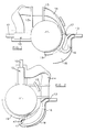
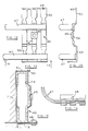
- a machine gun generally indicated at 10 is mounted for movement on a gun turret 11 which is mounted beneath the fuselage of an aircraft such as a helicopter.
- a barrel 12 of the gun is pointing forwardly away from the aircraft.
- the barrel has been rotated through 90° to extend laterally. It could equally well be turned through 90° in the opposite direction.
- the ammunition for the gun must be guided from the point 13 which is the end of a live ammunition conduit mounted on the aircraft, so as to enter the firing chamber of the gun, irrespective of its position.
- the flexible chuting 14 is supported adjacent to the gun on arms 15. However in order to accommodate movement of the gun and turret, it is necessary to allow a sufficient length of the inboard portion of the chuting to adopt a looped form, the loop 16 being relatively large when the gun is pointed laterally as shown in Figure 2, rather smaller when the gun is trained forwardly as shown in Figure 1, and reducing to a negligible size when the gun reaches its full lateral travel in the opposite direction of rotation (not shown).
- the inboard end of the chuting is fixed at 13 relative to the conduit.
- a portion of the chuting is attached at 17 to the gun turret.
- the intervening part of the chuting forms the loop 16, which is supported by a fixed plate 18 secured to the aircraft and also by a flange 19 secured to the turret. It will be seen that the relative positions of the support plate 18 and flange 19 change as the gun 10 is traversed.
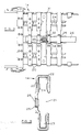
- the chuting is formed as a series of identical articulated links which can be seen in Figures 3 to 5 of the drawings.
- Each link 20 is of generally C shape having an open side at 21 and broader and narrower internal cross sections 22 and 23, to conform with the ammunition belt (not shown) passing through the chuting.
- the links 20 are connected loosely together by stainless steel plates 24 which have a sliding engagement and which are hooked one into another and which present a smooth internal profile, over which the ammunition belt can pass at high speed.
- the links 20 are capable of moving towards and away from each other to a limited extent from a nominal pitch separation of for example 25mm. In such chuting, a problem may arise when the links are compressed together or urged apart to the limit. In these conditions, the flexibility of the belt is very severely reduced.
- the present invention has been devised to ensure that the loop 16 of the flexible chuting is prevented from becoming compressed or collapsed or over-stretched, in response to movements of the gun and turret, throughout the length between the attachment at 13 to the conduit 13 and at 17 to the turret.
- Such distortions in the length of the chuting which reduce or increase the pitch between links can impose resistance to flexing of the chuting and could cause ammunition jams or restrict movement of the gun.
- the links may also undergo limited angular relative movement so that the chuting as a whole can curve round convex or concave bends and can also twist torsionally.
- the basic chuting is known and forms no part of the present invention.
- the bridge pieces 25 receive a flexible supporting spine 26 which is intended to support the links 20 against collapse on small radius bends.
- the flexible spine 26 is intended to stop the links from either jamming together or being too widely separated as the chuting adopts different configurations according to the movement of the gun 10. Between the points 13 and 17 shown in Figures 1 and 2 of the drawings, the overall length of the chuting is maintained constant by the flexible spine. This allows the chuting to bend into the necessary loops and twists and tends to smooth out the effect of any very sharp bends, preventing collapse of the links against each other or over-stretching.
- the spine 26 is not connected at any point between its two ends to the links 20 of the chuting. It is merely constrained within the bridges 25.
- the support means transfer the loading of the spine direct to major structural masses namely to the fixed support plate 18 and to the turret structure 11 without loading the articulated chuting itself.
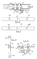
- the flexible spine 26 is made up of three thin gauge spring steel strips.
- One strip 27 shown in Figure 6 has a pair of circular attachment holes 28 at its opposed ends, intended to be attached to the support means.
- the remaining two stainless steel strips forming the flexible spine 26 are as shown in Figure 7 of the drawing at 29. Each of these has a round hole 28 a and a slightly elongated hole 30 for attachment to the support means. In this embodiment, the elongate holes 30 are positioned one at each end of the spine.
- the flexible spine 26 adopts a sandwich construction having one of the strips 29 at each outer face with the strip 27 sandwiched between. This permits slight relative adjustment of the strips forming the spine 26 to allow for bending while still maintaining the exact spacing of the points 13 and 17 where the support means are positioned.
- the use of more than one strip in this relatively adjustable relationship provides strength to the spine without substantial restriction of flexibility.
- the inboard end of the chuting 14 is connected at 13 to the live ammunition conduit and undergoes rather lesser stresses than the outboard end attached to the turret at 17. This is reflected in the support means used.
- the arrangement is as shown in Figures 3 and 4 of the drawings and uses a finger plate 31 shown in Figure 8.
- the finger plate has a pad 32 welded to its centre, carrying a bolt hole 33 which is the sole point of attachment to the inboard end of the flexible spine 26, being bolted through holes 28, 28 a and 30 of the strips 27 and 29.
- the bolting arrangement is shown in Figures 9 and 10 and it will be seen that, the strips 27 and 29 are not clamped tightly to the finger plate 31.
- a locator 34 (see Figures 4 and 9) has a head 35 against which the spine 26 is located around a shoulder 36 which spaces the head 35 from the finger plate 31.
- a nut 37 and washer 38 are used to secure the assembly together, the nut being applied from the outer face of the chuting as most clearly seen in Figure 4.
- the finger plate 31 itself is not secured to the chuting 14 but is secured to the fixed structure at 13, adjacent the live ammunition conduit.
- the arrangement is illustrated in Figure 10.
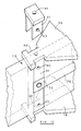
- the loop 16 of chuting is supported on a fixed support plate 18 as previously referred to.
- a similar fixed plate (not shown in Figures 1 and 2 of the drawings), overlies the chuting and this is shown at 39 in Figure 10.
- the drawing also diagrammatically shows the finger plate 31 and its strengthening pad 32 together with the inboard portion of the flexible spine 26 and the end of the live ammunition conduit.
- Each end of the finger plate 31 has a bolt hole 40.
- a fixing fork 41 is lowered as shown into a pair of location rebates 42 of the top support plate 39 and bolted at 43 to the upper bolt hole 40 of the finger.
- a similar lower fixing fork (not shown) is bolted to the lower bolt hole 40 from underneath the bottom support plate 18.
- the bridging webs of the upper and lower fork are bolted respectively by means of the bolt holes 44 to the upper and lower support plates 39 and 18.
- the arrangement is that the flexible spine 26 is attached only to the centre of the finger plate and not attached at any other point along the chuting loop 16, and the finger plate 31 is attached only to the top and bottom support plates 39 and 18 which are rigid with the structure of the aircraft, and the finger plate 31 is not attached to the flexible chuting.
- the flexible chuting affords recesses between the adjacent links 20. It is in one of these recesses that the finger plate is located, between the second and third links 20 of the chuting at the inboard end.
- the attachment of the outboard end to its support means on the turret 11 is similar to that previously described in relation to the inboard end.
- a slightly broader support means is used so as to spread the loading in a somewhat less concentrated fashion.
- the outboard portion of chuting is attached at 17 to the turret by means of a triple finger plate 45 shown in Figures 13 to 15 of the drawings.
- Each part of the triple finger plate 45 comprises a finger somewhat similar to that shown in Figure 8 but the three fingers are connected integrally together.
- a pad 46 is welded to the central finger and a bolted connection as shown in Figure 9 is used to secure on the flexible spine 26, the connection being shown in Figures 11 and 12 of the drawings.
- the triple finger plate 45 carries a pair of curved radius guides 47 which also assist in defining the minimum radius through which the chuting can be bent at the outboard end 17 where it is secured to the turret.
- the triple finger plate 45 is mounted within the recesses between the 37th, 38th, 39th and 40th links of the chuting as shown in Figures 11 and 12. Again, the triple finger plate 45 is not actually secured to the chuting at this point but is merely located.
- Figure 16 diagrammatically shows the support means for the chuting.
- the turret 11 carries a generally L shape flange 19.
- the triple finger 45 is bolted at 48 to this flange 19.
- the upper end of the triple finger 45 has a series of three slots 49 which receive prongs 50 of a trifurcated attachment plate 51 secured to the turret 11.
- the chuting indicated diagrammatically at 14 is enclosed within the assembly of the triple finger 45, the flange 19 and the trifurcated attachment plate 51 but is not rigidly secured to this assembly.
- the triple finger 45 has been referred to as a single integral item but it is manufactured in upper and lower parts 52, 53 welded to central finger elements 54, and also welded to the radius guides 47 previously referred to.
- the attachment pad 46 is welded to the centre of the central finger element 54.
Landscapes
- Engineering & Computer Science (AREA)
- General Engineering & Computer Science (AREA)
- Manipulator (AREA)
- Soil Working Implements (AREA)
- Agricultural Chemicals And Associated Chemicals (AREA)
- Advancing Webs (AREA)
- Emergency Lowering Means (AREA)
- Toys (AREA)
Priority Applications (1)
| Application Number | Priority Date | Filing Date | Title |
|---|---|---|---|
| AT89302591T ATE89401T1 (de) | 1988-03-31 | 1989-03-16 | Munitionsleitkanal fuer maschinengewehre. |
Applications Claiming Priority (2)
| Application Number | Priority Date | Filing Date | Title |
|---|---|---|---|
| GB888807714A GB8807714D0 (en) | 1988-03-31 | 1988-03-31 | Flexible ammunition chuting |
| GB8807714 | 1988-03-31 |
Publications (2)
| Publication Number | Publication Date |
|---|---|
| EP0335530A1 true EP0335530A1 (de) | 1989-10-04 |
| EP0335530B1 EP0335530B1 (de) | 1993-05-12 |
Family
ID=10634445
Family Applications (1)
| Application Number | Title | Priority Date | Filing Date |
|---|---|---|---|
| EP89302591A Expired - Lifetime EP0335530B1 (de) | 1988-03-31 | 1989-03-16 | Munitionsleitkanal für Maschinengewehre |
Country Status (6)
| Country | Link |
|---|---|
| US (1) | US4939978A (de) |
| EP (1) | EP0335530B1 (de) |
| JP (1) | JPH0244195A (de) |
| AT (1) | ATE89401T1 (de) |
| DE (1) | DE68906451T2 (de) |
| GB (1) | GB8807714D0 (de) |
Cited By (2)
| Publication number | Priority date | Publication date | Assignee | Title |
|---|---|---|---|---|
| WO2005031243A1 (de) * | 2003-09-23 | 2005-04-07 | Heckler & Koch Gmbh | Munitions-förderkette |
| FR3086745A1 (fr) * | 2018-10-01 | 2020-04-03 | Nexter Systems | Dispositif de suspension pour couloir de munitions |
Families Citing this family (3)
| Publication number | Priority date | Publication date | Assignee | Title |
|---|---|---|---|---|
| JP2007132361A (ja) * | 2005-11-08 | 2007-05-31 | Toto Ltd | 給水接続具 |
| US8752466B1 (en) * | 2011-12-07 | 2014-06-17 | Here Be Dragons Llc | Modular ammunition feed chute |
| US11725893B2 (en) | 2021-05-05 | 2023-08-15 | Meggitt Defense Systems, Inc. | Compact ammunition conveyor twister |
Citations (5)
| Publication number | Priority date | Publication date | Assignee | Title |
|---|---|---|---|---|
| US2351370A (en) * | 1942-11-30 | 1944-06-13 | Waldes Kohinoor Inc | Chute |
| US2477264A (en) * | 1944-05-13 | 1949-07-26 | Hughes Tool Co | Flexible feed chute |
| US2568229A (en) * | 1948-03-05 | 1951-09-18 | Mccord Corp | Expended clip cartridge chute for machine guns |
| US2890779A (en) * | 1958-03-07 | 1959-06-16 | Townsend Engineered Products I | Flexible conveyer chute |
| FR2436960A1 (fr) * | 1978-09-25 | 1980-04-18 | Oerlikon Buehrle Ag | Conduit souple pour l'amenee des munitions a une arme |
Family Cites Families (14)
| Publication number | Priority date | Publication date | Assignee | Title |
|---|---|---|---|---|
| US2007774A (en) * | 1933-06-09 | 1935-07-09 | Reginald F Sedgley | Cartridge magazine |
| GB574994A (en) * | 1937-03-13 | 1938-06-24 | Boulton Aircraft Ltd | Improvement in means for feeding ammunition to machine guns |
| GB572504A (en) * | 1939-08-04 | 1945-10-11 | Lewis Motley | Improvements in or relating to magazines and feed mechanisms for automatic guns or machine guns |
| US2419315A (en) * | 1941-10-27 | 1947-04-22 | Hughes Tool Co | Flexible chute |
| US2550837A (en) * | 1944-07-03 | 1951-05-01 | United Shoe Machinery Corp | Ammunition feeding means |
| US2464689A (en) * | 1945-08-13 | 1949-03-15 | Cons Vultee Aircraft Corp | Apparatus for charging ammunition boxes |
| GB624358A (en) * | 1945-12-10 | 1949-06-07 | Bristol Aeroplane Co Ltd | Improvements in or relating to ammunition chutes |
| US2740180A (en) * | 1950-03-06 | 1956-04-03 | Warren H Nobles | Adapter for ammunition chutes |
| US2915947A (en) * | 1956-02-01 | 1959-12-08 | United Shoe Machinery Corp | Cartridge projectors and belting means therefor |
| US3788189A (en) * | 1972-07-12 | 1974-01-29 | Gen Electric | Ammunition feeding system |
| DE2948685C2 (de) * | 1979-12-04 | 1983-05-11 | Rheinmetall GmbH, 4000 Düsseldorf | Patronengurtführung an einer höhenrichtbaren, automatischen Feuerwaffe |
| CA1157301A (en) * | 1980-05-23 | 1983-11-22 | Jean-Michel Schaulin | Marine firing weapon for fighting airborne targets, especially in zenith |
| DE3463689D1 (en) * | 1984-01-11 | 1987-06-19 | Oerlikon Buehrle Ag | Ammunition chute for a gun |
| EP0230111B1 (de) * | 1985-12-31 | 1989-08-09 | LUCAS INDUSTRIES public limited company | Vorrichtung zur Führung eines Patronenbandes |
-
1988
- 1988-03-31 GB GB888807714A patent/GB8807714D0/en active Pending
-
1989
- 1989-03-16 EP EP89302591A patent/EP0335530B1/de not_active Expired - Lifetime
- 1989-03-16 DE DE89302591T patent/DE68906451T2/de not_active Expired - Fee Related
- 1989-03-16 AT AT89302591T patent/ATE89401T1/de not_active IP Right Cessation
- 1989-03-27 US US07/328,868 patent/US4939978A/en not_active Expired - Fee Related
- 1989-03-30 JP JP1076850A patent/JPH0244195A/ja active Pending
Patent Citations (5)
| Publication number | Priority date | Publication date | Assignee | Title |
|---|---|---|---|---|
| US2351370A (en) * | 1942-11-30 | 1944-06-13 | Waldes Kohinoor Inc | Chute |
| US2477264A (en) * | 1944-05-13 | 1949-07-26 | Hughes Tool Co | Flexible feed chute |
| US2568229A (en) * | 1948-03-05 | 1951-09-18 | Mccord Corp | Expended clip cartridge chute for machine guns |
| US2890779A (en) * | 1958-03-07 | 1959-06-16 | Townsend Engineered Products I | Flexible conveyer chute |
| FR2436960A1 (fr) * | 1978-09-25 | 1980-04-18 | Oerlikon Buehrle Ag | Conduit souple pour l'amenee des munitions a une arme |
Cited By (2)
| Publication number | Priority date | Publication date | Assignee | Title |
|---|---|---|---|---|
| WO2005031243A1 (de) * | 2003-09-23 | 2005-04-07 | Heckler & Koch Gmbh | Munitions-förderkette |
| FR3086745A1 (fr) * | 2018-10-01 | 2020-04-03 | Nexter Systems | Dispositif de suspension pour couloir de munitions |
Also Published As
| Publication number | Publication date |
|---|---|
| EP0335530B1 (de) | 1993-05-12 |
| DE68906451D1 (de) | 1993-06-17 |
| ATE89401T1 (de) | 1993-05-15 |
| JPH0244195A (ja) | 1990-02-14 |
| US4939978A (en) | 1990-07-10 |
| GB8807714D0 (en) | 1988-05-05 |
| DE68906451T2 (de) | 1993-11-18 |
Similar Documents
| Publication | Publication Date | Title |
|---|---|---|
| CA2221816C (en) | Adjustable reflector device | |
| US4897768A (en) | Flashlight holder and mounted flashlight | |
| US4319125A (en) | Infra-red radiant heater system | |
| US4838236A (en) | Compound archery bow with adjustable draw length and pull weight | |
| US4293192A (en) | Solar reflector with flexible sheet tightly secured around form surfaces | |
| US5653214A (en) | Pivotal bowstring release mechanism | |
| US4909231A (en) | Dual anchor cable separator for compound bows | |
| EP0335530A1 (de) | Munitionsleitkanal für Maschinengewehre | |
| US4641451A (en) | Bipod mounting device and muzzle brake | |
| CA1285214C (en) | Multi-phase charge holder | |
| US4470216A (en) | Bipod mounting device and muzzle brake | |
| RU94022477A (ru) | Шарнирное приспособление и его применение | |
| CA2209464A1 (en) | Feeding device for poultry | |
| US4630185A (en) | Mechanical arm with two link members | |
| AU592773B2 (en) | Carrying strap for a weapon | |
| US4803970A (en) | Missile projecting device | |
| US4796597A (en) | Arrow rest | |
| EP0515336B1 (de) | Förderer mit seitlicher Greifvorrichtung | |
| SE467218B (sv) | Led | |
| CA2287074A1 (en) | Power supply chain | |
| US4353346A (en) | Compound bow | |
| SK218792A3 (en) | Device for holding of pipes, in particular the pipes in a power station | |
| CA2114444C (en) | Conveying system with conveyor chains | |
| EP0647813B1 (de) | Ausziehbare Vorrichtung zum Tragen von Objekten, insbesondere Beleuchtungsvorrichtungen von fotografischen Studio und dergleichen | |
| EP0905060A1 (de) | Förderbandträger |
Legal Events
| Date | Code | Title | Description |
|---|---|---|---|
| PUAI | Public reference made under article 153(3) epc to a published international application that has entered the european phase |
Free format text: ORIGINAL CODE: 0009012 |
|
| AK | Designated contracting states |
Kind code of ref document: A1 Designated state(s): AT DE FR GB IT |
|
| 17P | Request for examination filed |
Effective date: 19890914 |
|
| 17Q | First examination report despatched |
Effective date: 19910515 |
|
| GRAA | (expected) grant |
Free format text: ORIGINAL CODE: 0009210 |
|
| AK | Designated contracting states |
Kind code of ref document: B1 Designated state(s): AT DE FR GB IT |
|
| REF | Corresponds to: |
Ref document number: 89401 Country of ref document: AT Date of ref document: 19930515 Kind code of ref document: T |
|
| REF | Corresponds to: |
Ref document number: 68906451 Country of ref document: DE Date of ref document: 19930617 |
|
| ITF | It: translation for a ep patent filed | ||
| ET | Fr: translation filed | ||
| PGFP | Annual fee paid to national office [announced via postgrant information from national office to epo] |
Ref country code: GB Payment date: 19950307 Year of fee payment: 7 |
|
| PGFP | Annual fee paid to national office [announced via postgrant information from national office to epo] |
Ref country code: FR Payment date: 19950309 Year of fee payment: 7 Ref country code: DE Payment date: 19950309 Year of fee payment: 7 |
|
| PGFP | Annual fee paid to national office [announced via postgrant information from national office to epo] |
Ref country code: AT Payment date: 19950313 Year of fee payment: 7 |
|
| PG25 | Lapsed in a contracting state [announced via postgrant information from national office to epo] |
Ref country code: GB Effective date: 19960316 Ref country code: AT Effective date: 19960316 |
|
| GBPC | Gb: european patent ceased through non-payment of renewal fee |
Effective date: 19960316 |
|
| PG25 | Lapsed in a contracting state [announced via postgrant information from national office to epo] |
Ref country code: FR Effective date: 19961129 |
|
| PG25 | Lapsed in a contracting state [announced via postgrant information from national office to epo] |
Ref country code: DE Effective date: 19961203 |
|
| REG | Reference to a national code |
Ref country code: FR Ref legal event code: ST |
|
| PG25 | Lapsed in a contracting state [announced via postgrant information from national office to epo] |
Ref country code: IT Free format text: LAPSE BECAUSE OF NON-PAYMENT OF DUE FEES;WARNING: LAPSES OF ITALIAN PATENTS WITH EFFECTIVE DATE BEFORE 2007 MAY HAVE OCCURRED AT ANY TIME BEFORE 2007. THE CORRECT EFFECTIVE DATE MAY BE DIFFERENT FROM THE ONE RECORDED. Effective date: 20050316 |
|
| PLBE | No opposition filed within time limit |
Free format text: ORIGINAL CODE: 0009261 |
|
| STAA | Information on the status of an ep patent application or granted ep patent |
Free format text: STATUS: NO OPPOSITION FILED WITHIN TIME LIMIT |