EP0334899B1 - Vorrichtung zur aufeinanderfolgenden trocknung beider seiten einer papierbahn - Google Patents
Vorrichtung zur aufeinanderfolgenden trocknung beider seiten einer papierbahn Download PDFInfo
- Publication number
- EP0334899B1 EP0334899B1 EP88901398A EP88901398A EP0334899B1 EP 0334899 B1 EP0334899 B1 EP 0334899B1 EP 88901398 A EP88901398 A EP 88901398A EP 88901398 A EP88901398 A EP 88901398A EP 0334899 B1 EP0334899 B1 EP 0334899B1
- Authority
- EP
- European Patent Office
- Prior art keywords
- web
- dryer
- felt
- felt means
- drums
- Prior art date
- Legal status (The legal status is an assumption and is not a legal conclusion. Google has not performed a legal analysis and makes no representation as to the accuracy of the status listed.)
- Expired - Lifetime
Links
Images
Classifications
-
- D—TEXTILES; PAPER
- D21—PAPER-MAKING; PRODUCTION OF CELLULOSE
- D21F—PAPER-MAKING MACHINES; METHODS OF PRODUCING PAPER THEREON
- D21F5/00—Dryer section of machines for making continuous webs of paper
- D21F5/02—Drying on cylinders
- D21F5/04—Drying on cylinders on two or more drying cylinders
Definitions
- This invention relates to an apparatus for and a method of drying a web.
- DE-A-2 355 397 discloses an apparatus for sequentially drying both sides of a paper web, said apparatus comprising a plurality of groups of dryer drums, a plurality of guide rolls each being disposed between a respective pair of adjacent dryer drums, and a plurality of single dryer felts each being associated with a respective group of dryer drums and defining a continuous loop which extends in a sinusoidal configuration past altemate dryerdrums of the respective group and guide rolls with the web being sandwiched between the dryer felt and each dryer drum for heating a respective side of the web and with the dryer felt being sandwiched between the web and each guide roll.
- the known apparatus includes a web transfer section between two consecutive groups of dryer drums, said web transfer section comprising the downstream dryer felt associated with the downstream group of dryer drums and the upstream dryer felt associated with the upstream group of dryer drums and guide rolls for guiding said upstream dryer felt towards said downstream dryer felt with the web being supported and guided by the upstream dryer felt from the upstream group of dryer drums to the downstream group of dryer drums.
- the embodiments shown in figures 5, 6, 8 and 9 of the above-mentioned document do not include means for holding the web against the respective dryer felt while the dryer felt passes around the guide rolls. Thus there is a danger for the web to become separated from the respective dryer felt.
- the above-mentioned embodiments do not include means for completely avoiding an open draw in the web transfer sections. As a result the web in the web transfer sections is susceptible to breaks.
- US-A-4 359 827 discloses an apparatus for drying a web, said apparatus comprising a series of upper dryer drums and a series of lower grooved dryer drums each being disposed between a pair of adjacent upper dryer drums, and a fabric which passes alternately around upper and lower dryer drums in a sinusoidal configuration with the web being sandwiched between the fabric and each upper drums and with the fabric being sandwiched between the web and each lower drum. Since there is no direct contact between the lower dryer drums and the web any drying of the web during passage around the lower dryer drums is greatly reduced. In order to hold the web against thefabric vacuum boxes are provided between the upper and lower dryer drums.
- the lower drums are replaced with cylinders having foraminous major surfaces and that a vacuum is applied on the cylinder interiour so that the vacuum evacuates the grooves, thereby holding the web and fabric combination together onto the cylinder outer surface.
- the foraminous cylinders should have a diameter smaller than the dryer drums.
- the foraminous cylinders cannot be placed sufficiently close to the dryer drums to avoid a long fabric draw between consecutive dryer drums.
- the vacuum boxes between the upperdrums and the lowerdrums or lowerforaminous cylinders fabric wear will occur whenever the fabric comes into contact with the vacuum boxes because they have a stationary rigid surface.
- a BEL RUN type drying section in which a first drying section dries one side of the web and then a subsequent drying section dries the opposite side of the web.
- the single felt section may be made up of four groups of rollers. Typically, these groups indude drying rollers and suction rollers which provide no open draw in their configuration because the paper web is always supported by a dryer felt. As the web progresses from one group of dryers to the next, the same side of the web is always presented to the successive drying rollers. However, in order to present the opposite side of the web to a successive drying roller, it is necessary to transfer an unsupported web to a subsequent dryer felt.
- a further conventional drying apparatus is the so-called single-felted dryer section in which a joint run of the web and felt successively passes around upper and lower dryer drums in a sinusoidal configuration.
- this arrangement provides felt support for the web between successive upper and lower dryer drums, the lower dryer drums are virtually redundant in that the felt is sandwiched between the web and the drying roller thereby greatly reducing any drying of the web during passage around the lower drying rollers.
- such a single-felted dryer section still does not dry from both sides.
- An object of the present invention is to provide an apparatus and a method that overcome the aforementioned inadequacies of the prior art drying apparatuses and which permit a positive transfer of the web between successive groups of dryers in a no-open-draw-configuration such that alternate sides of the web can be dried thereby providing a paper product having uniform surface characteristics, surface strength and smoothness, and no tendency to curl.
- an apparatus for drying a web comprising a first single tier dryer section having a first plurality of dryer drums rotating in a first direction for drying a first side of the web, said first dryer section including a first plurality of suction rolls rotating in a second direction opposite to said first direction, said suction rolls being disposed between adjacent dryer drums of said first plurality of dryer drums, first dryer felt means for conveying the web in a serpentine path along said dryer drums and said suction rolls, a second single tier dryer section disposed downstream relative to said first dryer section and having a second plurality of dryer drums rotating in said second direction for drying a second side of the web, said second dryer section including a second plurality of suction rolls rotating in said first direction and disposed between adjacent dryer drums of said second plurality of dryer drums, second dryer felt means for conveying the web in a serpentine path along said second plurality of dryer drums and said second plurality of suction rolls, and means for guiding said first and second felt
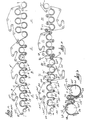
- Figure 1 is a side-elevational view of a conventional BEL RUN type drying section including groups A,B,C and D for drying a web of paper 1.
- the web 1 is guided in sinusoidal configuration around a plurality of dryer drums 2, 2' and 2" and suction transfer rolls 3, 3' and 3".
- a first felt 4 loops around a plurality of guide rolls 5, 5', 5", 5"' and 5"" and supports the web 1 as the web moves alternatively past dryer drums and suction rolls 3, 2, 3', 2', 3" and 2".
- a second group B of dryer drums 6, 6', and 6" has suction rolls 7, T and 7" disposed altemately therebetween such that a second felt 4' loops around the suction rolls and dryer drums 7, 6, 7', 6', 7" and 6" in sinusoidal configuration.
- the web 1 is unsupported by the felt 4 as the web 1 supported by the dryer drum 2" rotates adjacent to the second felt 4' so that the web 1 is transferred to the second felt 4' and around the suction roll 7.
- the same side 8 of the web 1 is brought into contact with the heating surfaces of the dryer rolls 2, 2', 2", 6, 6' and 6" so that the same side 8 is dried.
- the present invention enables the web 1A to be reversed from a first single tier dryer section A1 to a second single tier dryer section B1 so that during passage of the web 1A through the first section A1, a first side 8A of the web 1A comes into physical contact with the dryer drums 2A, 2A' and 2A" rotating in a first direction 20.
- a second side 9 of the web 1A comes into physical contact with the heating surface of dryer drums 6A, 6A' and 6A" rotating in a second direction 22 opposite to said firt direction 20.
- Figure 3 is an enlarged, fragmentary view of the transfer section shown in Figure 2 to show how the web 1A is reversed.
- the apparatus generally designated 10 for reversing the paper web 1A includes the last dryer drum 2A" of the first section A1 with the web extending around a portion of the circumference of the dryer drum 2A".
- a first felt 4A extends ar.ound a portion of the dryer drum 2A" such that the web 1A is sandwiched between the first felt 4A and the dryer drum 2A" for heating a first side 8A of the web 1A.
- a first suction roll 3A"' rotating in said second direction 22 is diposed downstream relative to the dryer drum 2A".
- the first suction roll 3A"' has an axis of rotation which is disposed parallel and spaced relative to the rotational axis of the dryer drum 2A".
- the first felt 4A and the web 1A extend around a portion of the circumference of the first suction roll 3A"' such that the first felt 4A is sandwiched between the web 1A and the first suction roll 3A"'.
- First guiding means 5A as shown in Figure 2, guide the first felt 4A away from the first suction roll 3A"'.
- a second suction roll 7A rotating in said first direction 20 is disposed adjacent to the first suction roll 3A"', the second suction roll 7A having an axis of rotation parallel and spaced relative to the axis of rotation of the first suction roll 3A"'.
- a second felt 4A' extends around the second suction roll 7A, and a second guiding means 12 shown in Figure 2 guides the second felt 4A' towards the second suction roll 7A such that the first and second felts 4A and 4A' respectively define therebetween a web transfer section generally designated 14 so that the web 1A is sandwiched between the felts 4A and 4A' during passage through the transfer section 14.
- the first dryer drum 6A of the second section B1 is disposed downstream relative to the second suction roll 7A with the dryer drum 6A having an axis of rotation parallel to the axis of rotation of the second suction roll 7A such that the web 1A is sandwiched between the second felt4A' and the dryer drum 6A for heating the second side 9 of the web 1 A.
- the first felt 4A is a continuous loop which extends in sinusoidal configuration past alternate dryer drums and suction rolls 3A, 2A, 3A', 2A' 3A", 2A" and 3A"' of the first section A1 such that the dryer drums 2A, 2A', 2A" physically contact the first side 8A of the web 1 A and the second plurality of dryer drums 6A, 6A' and 6A" physically contact the second side 9 of the web 1A so that alternate sides of the web 1A are sequentially dried.
- the first guiding means includes a first guide roll 5A for guiding the first felt 4A and the second guiding means includes the second guide roll 12 for guiding the second felt 4A'.
- alternate sides 8A and 9 of the paper web 1A are sequentially dried by the following method steps:
- the suction rolls are disposed below the dryer drums whereas in the second dryer section B1, the suction rolls are disposed above the dryer drums.
- a third single tier dryer section C1 is disposed downstream relative to the second single tier dryer section B1 for further drying the first side 8A of the web 1A
- a fourth single tier dryer section D1 is disposed downstream relative to the third single tier dryer section C1 for further drying the second side 9 of the web 1A.
- a further web transfer section is disposed between the second and third dryer sections B1 and C1
- yet another web transfer section is disposed between the third and fourth dryer sections C1 and D1.
Landscapes
- Paper (AREA)
- Drying Of Solid Materials (AREA)
Claims (10)
Priority Applications (1)
| Application Number | Priority Date | Filing Date | Title |
|---|---|---|---|
| AT88901398T ATE70868T1 (de) | 1986-12-02 | 1987-11-12 | Vorrichtung zur aufeinanderfolgenden trocknung beider seiten einer papierbahn. |
Applications Claiming Priority (4)
| Application Number | Priority Date | Filing Date | Title |
|---|---|---|---|
| JP185019/86 | 1986-12-02 | ||
| JP1986185019U JPS6389996U (de) | 1986-12-02 | 1986-12-02 | |
| JP18501986 | 1986-12-02 | ||
| PCT/US1987/003087 WO1988004206A2 (en) | 1986-12-02 | 1987-11-12 | Apparatus for sequentially drying both sides of a paper web |
Publications (3)
| Publication Number | Publication Date |
|---|---|
| EP0334899A1 EP0334899A1 (de) | 1989-10-04 |
| EP0334899B1 true EP0334899B1 (de) | 1991-12-27 |
| EP0334899B2 EP0334899B2 (de) | 1999-08-25 |
Family
ID=16163349
Family Applications (1)
| Application Number | Title | Priority Date | Filing Date |
|---|---|---|---|
| EP88901398A Expired - Lifetime EP0334899B2 (de) | 1986-12-02 | 1987-11-12 | Vorrichtung zur aufeinanderfolgenden trocknung beider seiten einer papierbahn |
Country Status (16)
| Country | Link |
|---|---|
| EP (1) | EP0334899B2 (de) |
| JP (1) | JPS6389996U (de) |
| KR (1) | KR940005201B1 (de) |
| CN (1) | CN1013598B (de) |
| AR (1) | AR246571A1 (de) |
| AT (1) | ATE70868T1 (de) |
| AU (1) | AU612349B2 (de) |
| BR (1) | BR8707946A (de) |
| CA (1) | CA1340582C (de) |
| DE (3) | DE334899T1 (de) |
| FI (2) | FI892657A7 (de) |
| IN (1) | IN168979B (de) |
| PH (1) | PH30381A (de) |
| PL (1) | PL158253B1 (de) |
| WO (1) | WO1988004206A2 (de) |
| ZA (1) | ZA879009B (de) |
Families Citing this family (20)
| Publication number | Priority date | Publication date | Assignee | Title |
|---|---|---|---|---|
| US4934067A (en) * | 1987-02-13 | 1990-06-19 | Beloit Corporation | Apparatus for drying a web |
| CA1328167C (en) * | 1987-02-13 | 1994-04-05 | Borgeir Skaugen | Apparatus for drying a web |
| US4918836A (en) * | 1987-02-13 | 1990-04-24 | Beloit Corporation | Tail cutter apparatus and method |
| US5404653A (en) * | 1987-02-13 | 1995-04-11 | Beloit Technologies, Inc. | Apparatus for drying a web |
| US5101577A (en) * | 1987-02-13 | 1992-04-07 | Beloit Corporation | Web transfer apparatus |
| US4807371A (en) * | 1987-02-13 | 1989-02-28 | Beloit Corporation | Apparatus for maintaining the edges of a web in conformity with a dryer felt |
| US5279049A (en) * | 1987-02-13 | 1994-01-18 | Beloit Technologies, Inc. | Process for the restrained drying of a paper web |
| US5144758A (en) * | 1987-02-13 | 1992-09-08 | Borgeir Skaugen | Apparatus for drying a web |
| US5241760A (en) * | 1987-02-13 | 1993-09-07 | Beloit Technologies, Inc. | Dryer apparatus |
| DE3721734A1 (de) * | 1987-07-01 | 1989-01-12 | Voith Gmbh J M | Verfahren zum trocknen einer laufenden bahn sowie papier- oder kartonmaschine zur durchfuehrung des verfahrens |
| FI82097C (fi) * | 1989-02-17 | 1991-01-10 | Valmet Paper Machinery Inc | Maongcylindertork i en pappersmaskin. |
| JPH0791798B2 (ja) * | 1989-12-22 | 1995-10-04 | 敷島紡績株式会社 | 抄紙用ドライヤーフエルト |
| US5184408A (en) * | 1990-01-19 | 1993-02-09 | J. M. Voith Gmbh | Dryer section |
| JP2558375B2 (ja) * | 1990-05-30 | 1996-11-27 | 三菱製紙株式会社 | 抄紙乾燥機の断紙検知方法およびそれに使用されるドライヤーカンバス |
| DE4142524A1 (de) * | 1991-12-21 | 1993-06-24 | Voith Gmbh J M | Trockenpartie |
| US5321899A (en) * | 1992-04-13 | 1994-06-21 | J. M. Voith Gmbh | Dry end |
| US5884415A (en) * | 1992-04-24 | 1999-03-23 | Beloit Technologies, Inc. | Paper making machine providing curl control |
| US5542193A (en) * | 1992-04-24 | 1996-08-06 | Beloit Technologies, Inc. | Dryer group for curl control |
| DE19934777A1 (de) * | 1999-07-23 | 2001-01-25 | Voith Paper Patent Gmbh | Trockenpartie |
| CN110172854A (zh) * | 2019-06-28 | 2019-08-27 | 夏德亮 | 一种基于气流变换的造纸烘干装置 |
Family Cites Families (6)
| Publication number | Priority date | Publication date | Assignee | Title |
|---|---|---|---|---|
| US2537129A (en) * | 1945-10-05 | 1951-01-09 | Beloit Iron Works | Structure for web transfers |
| FI53333C (fi) † | 1972-11-13 | 1978-04-10 | Valmet Oy | Torkningscylindergrupp i en flercylindertork foer en materialbana i synnerhet foer papper |
| US4359827B1 (en) * | 1979-11-05 | 1994-03-29 | Keith V Thomas | High speed paper drying |
| US4934067A (en) * | 1987-02-13 | 1990-06-19 | Beloit Corporation | Apparatus for drying a web |
| DE3807858A1 (de) * | 1988-03-10 | 1989-09-21 | Voith Gmbh J M | Verfahren zum trocknen einer materialbahn und vorrichtung zur durchfuehrung dieses verfahrens |
| DE3807856A1 (de) * | 1988-03-10 | 1989-09-21 | Voith Gmbh J M | Verfahren zum trocknen einer materialbahn und vorrichtung zur durchfuehrung dieses verfahrens |
-
1986
- 1986-12-02 JP JP1986185019U patent/JPS6389996U/ja active Pending
-
1987
- 1987-11-12 AU AU12439/88A patent/AU612349B2/en not_active Expired
- 1987-11-12 WO PCT/US1987/003087 patent/WO1988004206A2/en not_active Ceased
- 1987-11-12 BR BR8707946A patent/BR8707946A/pt not_active IP Right Cessation
- 1987-11-12 DE DE198888901398T patent/DE334899T1/de active Pending
- 1987-11-12 DE DE8717870U patent/DE8717870U1/de not_active Expired - Lifetime
- 1987-11-12 EP EP88901398A patent/EP0334899B2/de not_active Expired - Lifetime
- 1987-11-12 AT AT88901398T patent/ATE70868T1/de not_active IP Right Cessation
- 1987-11-12 KR KR1019880700915A patent/KR940005201B1/ko not_active Expired - Fee Related
- 1987-11-12 DE DE8888901398T patent/DE3775567D1/de not_active Expired - Lifetime
- 1987-11-30 CA CA000553056A patent/CA1340582C/en not_active Expired - Fee Related
- 1987-12-01 IN IN940/CAL/87A patent/IN168979B/en unknown
- 1987-12-01 ZA ZA879009A patent/ZA879009B/xx unknown
- 1987-12-01 PH PH36148A patent/PH30381A/en unknown
- 1987-12-02 PL PL1987269182A patent/PL158253B1/pl unknown
- 1987-12-02 CN CN87107232A patent/CN1013598B/zh not_active Expired
- 1987-12-21 AR AR87309466A patent/AR246571A1/es active
-
1989
- 1989-06-01 FI FI892657A patent/FI892657A7/fi not_active Application Discontinuation
-
1996
- 1996-01-25 FI FI960348A patent/FI960348A0/fi not_active Application Discontinuation
Also Published As
| Publication number | Publication date |
|---|---|
| CN87107232A (zh) | 1988-07-06 |
| DE8717870U1 (de) | 1991-03-28 |
| WO1988004206A2 (en) | 1988-06-16 |
| FI960348A7 (fi) | 1996-01-25 |
| DE334899T1 (de) | 1990-07-26 |
| FI892657L (fi) | 1989-06-01 |
| FI892657A0 (fi) | 1989-06-01 |
| EP0334899A1 (de) | 1989-10-04 |
| PL269182A1 (en) | 1988-08-18 |
| AR246571A1 (es) | 1994-08-31 |
| WO1988004206A3 (en) | 1988-06-30 |
| CA1340582C (en) | 1999-06-08 |
| PL158253B1 (pl) | 1992-08-31 |
| JPS6389996U (de) | 1988-06-10 |
| DE3775567D1 (de) | 1992-02-06 |
| PH30381A (en) | 1997-04-15 |
| FI892657A7 (fi) | 1989-06-01 |
| KR890700180A (ko) | 1989-03-10 |
| AU1243988A (en) | 1988-06-30 |
| KR940005201B1 (ko) | 1994-06-13 |
| EP0334899B2 (de) | 1999-08-25 |
| BR8707946A (pt) | 1990-02-13 |
| ATE70868T1 (de) | 1992-01-15 |
| FI960348A0 (fi) | 1996-01-25 |
| ZA879009B (en) | 1988-09-28 |
| IN168979B (de) | 1991-08-03 |
| AU612349B2 (en) | 1991-07-11 |
| CN1013598B (zh) | 1991-08-21 |
Similar Documents
| Publication | Publication Date | Title |
|---|---|---|
| EP0334899B1 (de) | Vorrichtung zur aufeinanderfolgenden trocknung beider seiten einer papierbahn | |
| EP0345266B1 (de) | Vorrichtung zur trocknung einer bahn | |
| US4483083A (en) | Drying and runnability for high speed paper machines | |
| US4183148A (en) | Paper machine drying section and method of operating the same | |
| US4972608A (en) | Multi-cylinder dryer for a paper machine with supported draw of web | |
| US4172007A (en) | Method and apparatus for reliably transporting a web in a paper making machine | |
| JPS59137595A (ja) | 紙又は板紙用ドライヤ | |
| US5933977A (en) | Curl control with dryer aircaps | |
| US5184408A (en) | Dryer section | |
| EP1003931B1 (de) | Alternierende, ohne offenen zug gekoppelte oben- und untenbefilzte trockener | |
| KR19980703709A (ko) | 중간 캘린더링이 설치된 제지기계의 건조기부 | |
| US5241761A (en) | Dryer section for a paper making machine with differing suction rolls | |
| US5666741A (en) | Drying section with additional press nip | |
| US5175945A (en) | Apparatus for drying a web | |
| CA2258235A1 (en) | Method and device for contact-free drying of a paper web or equivalent | |
| US5636452A (en) | Paper drying machine and method for drying a paper web in a paper drying machine | |
| US4186496A (en) | Web drier section | |
| CA2211185A1 (en) | Single tier dryer section with dual reversing rolls | |
| CA2060015A1 (en) | Dryer group web transfer region for paper making machine | |
| US6070340A (en) | Cylinder group provided with single-wire draw in the dryer section of a paper machine and dryer section that included such cylinder groups | |
| KR100458848B1 (ko) | 커얼을억제하는드라이어에어캡을구비한제지기의드라이어섹션 |
Legal Events
| Date | Code | Title | Description |
|---|---|---|---|
| PUAI | Public reference made under article 153(3) epc to a published international application that has entered the european phase |
Free format text: ORIGINAL CODE: 0009012 |
|
| 17P | Request for examination filed |
Effective date: 19890525 |
|
| AK | Designated contracting states |
Kind code of ref document: A1 Designated state(s): AT BE CH DE FR GB IT LI LU NL SE |
|
| ITCL | It: translation for ep claims filed |
Representative=s name: RICCARDI SERGIO & CO. |
|
| RBV | Designated contracting states (corrected) |
Designated state(s): AT DE FR GB IT SE |
|
| TCAT | At: translation of patent claims filed | ||
| 17Q | First examination report despatched |
Effective date: 19900523 |
|
| DET | De: translation of patent claims | ||
| GRAA | (expected) grant |
Free format text: ORIGINAL CODE: 0009210 |
|
| AK | Designated contracting states |
Kind code of ref document: B1 Designated state(s): AT DE FR GB IT SE |
|
| REF | Corresponds to: |
Ref document number: 70868 Country of ref document: AT Date of ref document: 19920115 Kind code of ref document: T |
|
| ET | Fr: translation filed | ||
| REF | Corresponds to: |
Ref document number: 3775567 Country of ref document: DE Date of ref document: 19920206 |
|
| ITF | It: translation for a ep patent filed | ||
| PLBI | Opposition filed |
Free format text: ORIGINAL CODE: 0009260 |
|
| PLBI | Opposition filed |
Free format text: ORIGINAL CODE: 0009260 |
|
| 26 | Opposition filed |
Opponent name: J.M. VOITH GMBH Effective date: 19920825 |
|
| 26 | Opposition filed |
Opponent name: J.M. VOITH GMBH Effective date: 19920825 Opponent name: VALMET PAPER MACHINERY INC. Effective date: 19920925 |
|
| PLAB | Opposition data, opponent's data or that of the opponent's representative modified |
Free format text: ORIGINAL CODE: 0009299OPPO |
|
| R26 | Opposition filed (corrected) |
Opponent name: J.M. VOITH GMBH * 920925 VALMET PAPER MACHINERY IN Effective date: 19920825 |
|
| REG | Reference to a national code |
Ref country code: GB Ref legal event code: 732E |
|
| EAL | Se: european patent in force in sweden |
Ref document number: 88901398.3 |
|
| REG | Reference to a national code |
Ref country code: FR Ref legal event code: TP |
|
| PGFP | Annual fee paid to national office [announced via postgrant information from national office to epo] |
Ref country code: GB Payment date: 19961014 Year of fee payment: 10 |
|
| APAE | Appeal reference modified |
Free format text: ORIGINAL CODE: EPIDOS REFNO |
|
| RAP2 | Party data changed (patent owner data changed or rights of a patent transferred) |
Owner name: BELOIT TECHNOLOGIES, INC. |
|
| APAC | Appeal dossier modified |
Free format text: ORIGINAL CODE: EPIDOS NOAPO |
|
| PLAW | Interlocutory decision in opposition |
Free format text: ORIGINAL CODE: EPIDOS IDOP |
|
| PLAW | Interlocutory decision in opposition |
Free format text: ORIGINAL CODE: EPIDOS IDOP |
|
| PUAH | Patent maintained in amended form |
Free format text: ORIGINAL CODE: 0009272 |
|
| STAA | Information on the status of an ep patent application or granted ep patent |
Free format text: STATUS: PATENT MAINTAINED AS AMENDED |
|
| 27A | Patent maintained in amended form |
Effective date: 19990825 |
|
| AK | Designated contracting states |
Kind code of ref document: B2 Designated state(s): AT DE FR GB IT SE |
|
| ET3 | Fr: translation filed ** decision concerning opposition | ||
| ITF | It: translation for a ep patent filed | ||
| REG | Reference to a national code |
Ref country code: GB Ref legal event code: IF02 |
|
| APAH | Appeal reference modified |
Free format text: ORIGINAL CODE: EPIDOSCREFNO |
|
| PGFP | Annual fee paid to national office [announced via postgrant information from national office to epo] |
Ref country code: AT Payment date: 20061113 Year of fee payment: 20 |
|
| PGFP | Annual fee paid to national office [announced via postgrant information from national office to epo] |
Ref country code: SE Payment date: 20061114 Year of fee payment: 20 |
|
| PGFP | Annual fee paid to national office [announced via postgrant information from national office to epo] |
Ref country code: DE Payment date: 20061124 Year of fee payment: 20 Ref country code: FR Payment date: 20061124 Year of fee payment: 20 |
|
| PGFP | Annual fee paid to national office [announced via postgrant information from national office to epo] |
Ref country code: IT Payment date: 20061130 Year of fee payment: 20 |
|
| EUG | Se: european patent has lapsed | ||
| PG25 | Lapsed in a contracting state [announced via postgrant information from national office to epo] |
Ref country code: GB Free format text: LAPSE BECAUSE OF NON-PAYMENT OF DUE FEES Effective date: 19971112 |
|
| PLAB | Opposition data, opponent's data or that of the opponent's representative modified |
Free format text: ORIGINAL CODE: 0009299OPPO |