EP0334885B1 - Verfahren und vorrichtung zum herstellen einer brücke für verankerungselemente im dentin - Google Patents
Verfahren und vorrichtung zum herstellen einer brücke für verankerungselemente im dentin Download PDFInfo
- Publication number
- EP0334885B1 EP0334885B1 EP88900148A EP88900148A EP0334885B1 EP 0334885 B1 EP0334885 B1 EP 0334885B1 EP 88900148 A EP88900148 A EP 88900148A EP 88900148 A EP88900148 A EP 88900148A EP 0334885 B1 EP0334885 B1 EP 0334885B1
- Authority
- EP
- European Patent Office
- Prior art keywords
- bridge
- elements
- modular
- anchorage
- modular elements
- Prior art date
- Legal status (The legal status is an assumption and is not a legal conclusion. Google has not performed a legal analysis and makes no representation as to the accuracy of the status listed.)
- Expired
Links
- 210000004268 dentin Anatomy 0.000 title claims abstract description 18
- 238000000034 method Methods 0.000 title claims description 13
- 238000012545 processing Methods 0.000 claims abstract description 33
- 238000005304 joining Methods 0.000 claims abstract description 15
- 238000003466 welding Methods 0.000 claims abstract description 11
- RTAQQCXQSZGOHL-UHFFFAOYSA-N Titanium Chemical compound [Ti] RTAQQCXQSZGOHL-UHFFFAOYSA-N 0.000 claims abstract description 8
- 229910052719 titanium Inorganic materials 0.000 claims abstract description 8
- 239000010936 titanium Substances 0.000 claims abstract description 8
- 238000010276 construction Methods 0.000 claims abstract description 6
- 238000006073 displacement reaction Methods 0.000 claims description 17
- 238000005520 cutting process Methods 0.000 claims description 10
- 238000004519 manufacturing process Methods 0.000 claims description 10
- 238000004088 simulation Methods 0.000 claims description 6
- 230000013011 mating Effects 0.000 claims 2
- 238000013461 design Methods 0.000 description 3
- 230000001419 dependent effect Effects 0.000 description 2
- 238000011161 development Methods 0.000 description 2
- 230000000694 effects Effects 0.000 description 2
- 239000000463 material Substances 0.000 description 2
- 238000003860 storage Methods 0.000 description 2
- 238000004026 adhesive bonding Methods 0.000 description 1
- 230000001747 exhibiting effect Effects 0.000 description 1
- 239000007943 implant Substances 0.000 description 1
- 238000002513 implantation Methods 0.000 description 1
- 230000003993 interaction Effects 0.000 description 1
- 238000012986 modification Methods 0.000 description 1
- 230000004048 modification Effects 0.000 description 1
- 238000000465 moulding Methods 0.000 description 1
- 239000000725 suspension Substances 0.000 description 1
- 238000012546 transfer Methods 0.000 description 1
Images

Classifications
-
- A—HUMAN NECESSITIES
- A61—MEDICAL OR VETERINARY SCIENCE; HYGIENE
- A61C—DENTISTRY; APPARATUS OR METHODS FOR ORAL OR DENTAL HYGIENE
- A61C8/00—Means to be fixed to the jaw-bone for consolidating natural teeth or for fixing dental prostheses thereon; Dental implants; Implanting tools
- A61C8/0048—Connecting the upper structure to the implant, e.g. bridging bars
-
- A—HUMAN NECESSITIES
- A61—MEDICAL OR VETERINARY SCIENCE; HYGIENE
- A61C—DENTISTRY; APPARATUS OR METHODS FOR ORAL OR DENTAL HYGIENE
- A61C13/00—Dental prostheses; Making same
- A61C13/0003—Making bridge-work, inlays, implants or the like
Definitions
- the present invention relates to a method for producing by mechanical means a bridge made of titanium for anchorage elements implanted in the dentine of a tooth.
- the aforementioned bridge constitutes the framework for an artificial dental structure, and the dental structure is capable of being attached to the anchorage elements via the bridge.
- the bridge is of the kind which is built up of modular elements which are treated for the purpose of adapting them one to the other and of being joined together.
- the invention also relates to an apparatus for the execution of the aforementioned method.
- the bridge structure in this case consists of a framework made of an appropriate material and an artificial dental structure built up on the frame, which dental structure is secured to the pins with screws, preferably made of titanium.
- This kind of framework is associated with the need to be able to achieve rational production without being obliged to depart from the requirement for an accurate fit on the pins.
- the degree of lateral accuracy is high (e.g. 10 ⁇ 2 mm).
- the requirement in respect of the strength of the bridge is high, at the same time as which the bridge framework must be capable of being accommodated within the dimensions of the artificial dental structure.
- the requirement imposed on the artificial dental structure is that it must correspond to the natural situation which it is to replace.
- the object of the present invention is to create a method which will resolve, amongst other things, the problem outlined above, and the method may accordingly be regarded as being essentially characterized in that, in conjunction with the performance in a treatment unit of one or more first treatment stages for the construction of the bridge, identification data introduced or utilized in the one or more first treatment stages relating to the individual different heights of the anchorage elements above the dentine or a plane passing through same, and different relative inclinations and the positions and directions of the modular elements in relation to one another and to the anchorage elements are obtained and stored, and in that a processing unit which performs a subsequent processing stage is controlled depending on the data thus obtained and stored, so that any projecting components present in the bridge between the attachment components of the bridge are assured a connection via contact surfaces.
- a working model which constitutes an internal impression of the jaw.
- the working model is secured to a component which forms part of the treatment unit and is so arranged as to be capable of displacement and/or rotation in its own plane.
- Contact surfaces between two first modular elements situated adjacent to one another in the bridge are produced in a first displaced and/or rotated angular position of the part, and so on.
- Data relating to the first and second displaced and/or rotated angular positions of the part are recorded and utilized in a joining machine, for example a welding machine (laser welding machine), forming the processing unit, for the purpose of joining together modular elements at the produced contact surfaces.
- a welding machine laser welding machine
- the aforementioned processing device can be so arranged for this purpose that it is controlled for the purpose of interacting with a first modular element secured temporarily to a selected anchorage element in same, for the purpose of producing the contact surface on the first modular element.
- the first modular element is removed once its contact surface has been produced, and a second modular element, which is to be situated adjacent to the first modular element in the bridge, is fitted to the working model on an adjacent anchorage element.
- the processing device is guided for this purpose into interaction with the second modular element for the purpose of producing its contact surface, which is to make contact with the aforementioned contact surface on the first modular element.
- This process stage is performed on the other modular elements until all the contact surfaces have been produced, whereupon all the modular elements are attached to the working model.
- An apparatus for the execution of the method indicated in the foregoing is characterized essentially in that it comprises, amongst other things, treatment and processing units, whereby identification data introduced or utilized in the treatment unit relating to the individual different heights of the anchorage elements above the dentine or a plane passing through same, and different relative inclinations and the positions and directions of the modular elements in relation to one another are capable of being determined and stored.
- the processing unit is capable of being controlled, by the use of the established identification data, for the purpose of performing its processing of the modular elements in order to achieve a bridge structure in which the projecting components of the bridge extend between the attachment elements of the bridge.
- a further development of the new apparatus involves, amongst other things, the treatment unit exhibiting a part with a mounting surface for the attachment of a working model which constitutes an internal impression of the jaw with the appropriate dummies representing implanted anchorage elements.
- the aforementioned part is in this case capable of displacement and/or rotation in the plane of the mounting surface and possibly in the sense of the height of the mounting surface.
- the treatment unit in this case also exhibits a processing device for producing the contact surfaces on the modular units when these are applied one by one to the working model.
- the treatment device is also arranged for the purpose of determining the displacement and/or angles of rotation at which the different modular elements are processed.
- the processing unit is so arranged in the latter case as to perform the joining operation (e.g. laser welding) depending on the data relating to the aforementioned displacements and/or rotations.
- a conventional cutting wheel can be used for the purpose of producing the contact surfaces.
- the cutting wheel can be so arranged in this case as to be capable of lateral displacement in order to compensate for the thickness of the wheel. Compensation can be effected alternatively or in a supplementary fashion by the lateral displacement of the part which is capable of lateral displacement.
- the apparatus can contain simulating devices for the simulation of the form of the bridge and the form and positions of the contact surfaces.
- the processing device in this case utilizes data from the simulation devices as the aforementioned identification data.
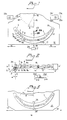
- the designation 1 is used in the Figure in respect of a working model.
- the working model is produced in a previously disclosed manner and constitutes an impression or moulding of the dentine 2 together with surrounding parts of the person who is to use the artificial dental structure.
- the working model includes dummies 3, 3b in accordance with Fig. 2 attached to pins which are implanted in a previously disclosed manner in the person's jaw. Attached to the dummies are distance pieces 4, the design and application of which are also previously disclosed.
- a characteristic feature of the implanted pins is that they adopt individual positions in the dentine, which means that the distance devices project upwards above the dentine to different heights and at different angles of inclination.
- This is illustrated in Fig. 2 by the external pins 3′ and 3 ⁇ having different heights H and H′.
- the pin 3′ is also inclined in relation to the vertical axis 5 in the actual section in accordance with Fig. 2.
- the angle between the axis 3a of the pin and the aforementioned vertical axis is indicated by ⁇ .
- the pin 3 ⁇ exhibits the inclination 0° in the illustrative embodiment shown here.
- the pin can also be inclined in the other direction, for example perpendicularly to the plane of the paper in accordance with fig. 2.
- the distances H and H′ are indicated respectively with their starting points on a plane 6 which extends perpendicularly to the figure plane in Fig. 2 and through the working model.
- the different heights H, H′ are dependent on the appearance of the individual dentine, and any inclinations of the implanted pins are dependent on the fact that it is not possible to predict the directions of the pins inserted by operation.
- the bridge framework which is made of titanium or some other hard material, is built up of modular elements, two of which are indicated by 7 and 8 in Figs. 1 and 2. These designs of the modular elements can vary within wide limits. Modular elements have been chosen in the present case which exhibit attachment components 7a and 8a with projecting components 7b, 7c and 8b, 8c arranged therein. In conjunction with the construction of the bridge the modular elements are tested in respect of their fit one with the other with regard to the production of the contact surfaces 9. The aforementioned contact surfaces may be situated on the projecting components illustrated in the Figures. Contact surfaces may also be provided, however, on the attachment component 7a and 8a, in which case the projecting component on an adjacent element extends all the way to the central component concerned.
- the respective distance pieces 4 are screwed securely to the respective pins 3 with the help of a screw 4a.
- This anchorage is previously disclosed and is not affected by the invention, except in the event of the bridge structure being required to be capable of being attached/screwed securely to the distance device 4a.
- the screw 4a is provided with a threaded hole for the screw 10.
- the aforementioned screw 10 extends from the upper surface of the respective attachment component, and the attachment component is provided with an internal shoulder to permit attachment with the help of the screw 10.
- the modular elements can contain attachment components 7a and 8a which are capable of displacement in relation to the projecting components 7b, 7c And 8b, 8c.
- a certain level equalization effect can be achieved in this way with the help of the individual displacement of the attachment component of the modular element in relation to the projecting parts.
- the modular elements can thus be given a uniform design where the projecting parts originate at the same angle (e.g. a right-angle) from the attachment component. It is possible, however, to cause the projecting parts to originate from their respective attachment components at different angles, so that individual matching in the sense of the height of the jawbone can take place.
- Each of the modular elements can be provided with one or more projecting parts in relation to the attachment component.
- the projecting parts and the attachment components in the bridge structure are given a flexible form, at the same time as the strength requirements are satisfied.
- the bridge components should exhibit a clearance to the upper surface of the dentine.
- the requirement is thus that the bridge elements must essentially make contact with the upper surface 11 of the dentine.
- the expression 'essentially' shall be interpreted with a broad meaning in this instance, and the level equalization effect achieved by means of the capacity of the attachment components for displacement relative to the projecting parts shall be ignored.
- the bridge structure is also essential for the bridge structure to be capable of being executed with comparatively narrow dimensions, so that it is accommodated within the artificial dental structure, which is not shown in the Figures.
- the requirement imposed on the bridge structure is thus that the projecting components shall be essentially in line with the direction of the dentine, including in the sense of the width or depth of the dentine.
- the treatment 12 is also provided with a cutting wheel illustrated symbolically by 34.
- the suspension of the device 12 and the cutting wheel 34 and the driving of the latter can be executed in a previously disclosed manner.
- the wheel rotates about its own axis 34a.
- the contact surfaces 9 between the modular elements are produced with the help of the device 12 and the wheel 34.
- the operation proceeds in such a way that a first modular element, for example the modular element 7, is clamped temporarily in position, whereupon the device 12 is displaced and/or rotated around axis 16 through an angle so that the predetermined cutting point on the projecting component 7b on the modular element is brought into line with the cutting wheel 34. With the help of the latter the projecting component 7b is cut at the predetermined point.
- the modular element 7 is then loosened and rotated or removed and is applied to the modular element 8, the projecting component 8b of which is cut with the device 12 in the same position of displacement and/or angular rotation, with compensation for the thickness of the disc.
- the set position of displacement and/or angular rotation can be sensed with sensing devices 19, 21 and 20, 22.
- the aforementioned sensing devices exhibit outputs 21a and 22a which are fed into the inputs 21a′ and 22a′ of a storage unit 23, which is capable of establishing and storing the various adjustment positions for the device 12 in conjunction with the production of the different contact surfaces 9 of the modular elements.
- the aforementioned data can be obtained at outputs 23a and 23b.
- control unit 24 for a processing unit 25, which in this instance consists of a laser welding machine, an adhesive bonding machine or a joining machine of some other kind.
- the control unit receives the data from the sensing and storage unit 23 via its inputs 24a and 24b. Control signals are obtained at the outputs 24a′ and 24b′ of the control unit.
- the joining machine 25 is controlled in a previously disclosed manner via these control outputs into the different positions which represent the contact surfaces on the modular elements.
- the working model 1 is clamped to a part on the machine 25 which is able to move in a corresponding manner to the part 12 in the treatment machine.
- the part in question is thus capable of displacement in the directions of the arrows 13, 13′ and 14, 14′, that is to say the x-coordinate, and capable of rotation through the angle of rotation ⁇ ′.
- the machine 25 will possess equivalent mobility.
- the joining function for the processing component is symbolized by a pair of welding electrodes 26, 26′. These welding electrodes are given a fixed position, and the machine 25 causes the contact surfaces to rotate forwards to the electrodes 26, 26′ depending on the control instructions given by the control unit 24.
- Figs. 4 and 5 illustrate an arrangement which is suitable in the event of the processing stations being geographically separated, so that the working model 1 must be moved or transported.
- the working model is fixed in a previously disclosed manner to a holder 27 arranged with securing devices 27a for its temporary attachment to a first chuck device 28 of a previously disclosed kind.
- the chuck device is a part of rotating devices (not shown) so arranged as to be capable of causing the chuck device to rotate about an axis of rotation 29, 33 for the purpose of adjusting the elements 8b/8c in relation to the cutting device 21.
- the latter device is arranged on a rotating device 30, via the shaft 30a of the latter.
- the rotating device can be driven electrically, pneumatically or hydraulically, etc.
- the holder 27 is arranged for torsional attachment to the chuck device 28.
- the aforementioned attachment is achieved by means of a searching device comprising an inclined surface 27b and a heel, etc.
- the holder is imparted by means of the searching device with a predetermined angular rotational position in the chuck device 28, which in turn is adjustable in a starting position with the help of a scale, 17, 18 heel or similar.
- the data for the identification of the contact surfaces can be executed in a different manner, just as other functions described in the foregoing.
- the bridge structure and its joining of the modular elements can thus be simulated with the help of previously disclosed simulation devices, for example computer equipment. Construction and joining are calculated from the three-dimensional assumptions which relate to the construction and attachment of the bridge structure. With the help of the data thus obtained, the modular units are each processed individually and are combined into a combination station.
Landscapes
- Health & Medical Sciences (AREA)
- Animal Behavior & Ethology (AREA)
- Public Health (AREA)
- Dentistry (AREA)
- Epidemiology (AREA)
- Life Sciences & Earth Sciences (AREA)
- Oral & Maxillofacial Surgery (AREA)
- General Health & Medical Sciences (AREA)
- Veterinary Medicine (AREA)
- Orthopedic Medicine & Surgery (AREA)
- Dental Tools And Instruments Or Auxiliary Dental Instruments (AREA)
- Dental Prosthetics (AREA)
- Joining Of Building Structures In Genera (AREA)
- Bridges Or Land Bridges (AREA)
- Prostheses (AREA)
Claims (9)
Priority Applications (1)
| Application Number | Priority Date | Filing Date | Title |
|---|---|---|---|
| AT88900148T ATE77041T1 (de) | 1986-12-09 | 1987-12-02 | Verfahren und vorrichtung zum herstellen einer bruecke fuer verankerungselemente im dentin. |
Applications Claiming Priority (2)
| Application Number | Priority Date | Filing Date | Title |
|---|---|---|---|
| SE8605272 | 1986-12-09 | ||
| SE8605272A SE455156B (sv) | 1986-12-09 | 1986-12-09 | Metod och anordning for att till forankringselement i tandben framstella en brygga |
Publications (2)
| Publication Number | Publication Date |
|---|---|
| EP0334885A1 EP0334885A1 (de) | 1989-10-04 |
| EP0334885B1 true EP0334885B1 (de) | 1992-06-10 |
Family
ID=20366563
Family Applications (1)
| Application Number | Title | Priority Date | Filing Date |
|---|---|---|---|
| EP88900148A Expired EP0334885B1 (de) | 1986-12-09 | 1987-12-02 | Verfahren und vorrichtung zum herstellen einer brücke für verankerungselemente im dentin |
Country Status (8)
| Country | Link |
|---|---|
| US (1) | US5052928A (de) |
| EP (1) | EP0334885B1 (de) |
| JP (1) | JP2832533B2 (de) |
| AT (1) | ATE77041T1 (de) |
| CA (1) | CA1300935C (de) |
| DE (1) | DE3779764T2 (de) |
| SE (1) | SE455156B (de) |
| WO (1) | WO1988004158A1 (de) |
Families Citing this family (32)
| Publication number | Priority date | Publication date | Assignee | Title |
|---|---|---|---|---|
| SE460944C (sv) * | 1988-11-24 | 1992-07-13 | Titanbron I Aahus Ab | Saett att tillverka en anordning foer uppbaerning av konstgjorda taender |
| SE464959B (sv) * | 1990-01-18 | 1991-07-08 | Nobelpharma Ab | Avtryckstopp utfoerd i elastiskt material |
| FR2658716A1 (fr) * | 1990-02-27 | 1991-08-30 | Guis Paul | Implant dentaire, inter-osseux; pour mandibule edentee totale. |
| CH681709A5 (de) * | 1990-05-16 | 1993-05-14 | Mikrona Technologie Ag | |
| SE470049B (sv) * | 1991-03-01 | 1993-11-01 | Nobelpharma Ab | Anordning vid bro som är individualanpassad till i tandben implanterade element |
| US5221204A (en) * | 1991-09-23 | 1993-06-22 | Kruger Bernard M | Dental implant product and method of making |
| CH686114A5 (fr) * | 1991-09-27 | 1996-01-15 | Helmut Hader | Structure de support d'une prothese dentaire. |
| US5322436A (en) * | 1992-10-26 | 1994-06-21 | Minnesota Mining And Manufacturing Company | Engraved orthodontic band |
| US5427906A (en) * | 1993-05-27 | 1995-06-27 | Hansen; Gorm P. | System for bracing dental implants or natural tooth roots to secure artificial teeth |
| NL9301308A (nl) * | 1993-07-26 | 1995-02-16 | Willem Frederick Van Nifterick | Werkwijze voor het vastzetten van een tandprothese op implantaten in het kaakbeen van een patiënt en middel te gebruiken daarbij. |
| US5419700A (en) * | 1993-10-22 | 1995-05-30 | Sillard; Rannar | Reinforced joint for fitting dental appliances and method for fabricating same |
| SE503072C2 (sv) * | 1994-07-04 | 1996-03-18 | Nobelpharma Ab | Metod och anordning utnyttjande en eller flera trådframmatningsbanor vid framställning av artificiella stödorgan till människokropppar |
| US5575651A (en) * | 1994-07-27 | 1996-11-19 | Weissman; Bernard | Prosthetic dental bridge foundation |
| US5630717A (en) * | 1995-05-01 | 1997-05-20 | Zest Anchors, Inc. | Dental implant bar system and method |
| US5725376A (en) * | 1996-02-27 | 1998-03-10 | Poirier; Michel | Methods for manufacturing a dental implant drill guide and a dental implant superstructure |
| US7331786B2 (en) * | 1996-02-27 | 2008-02-19 | Technique D'usinage Sinlab Inc. | Manufacturing a dental implant drill guide and a dental implant superstructure |
| SE507803C2 (sv) * | 1996-11-13 | 1998-07-13 | Titanbron Foervaltnings Ab | Sätt och anordning för bearbetning av en brokonstruktion |
| US6056547A (en) * | 1997-03-05 | 2000-05-02 | Medentech, Inc. | Impression and foundation system for implant-supported prosthesis |
| FI971622L (fi) * | 1997-04-17 | 1998-10-18 | Kari Luotio | Hammasimplanttijärjestelmä ja menetelmä sen valmistamiseksi |
| US6039569A (en) * | 1997-08-12 | 2000-03-21 | Jeneric/Pentron Incorporated | Fiber-reinforced dental structures and method of manufacture thereof |
| US5975904A (en) * | 1997-12-05 | 1999-11-02 | Spiegel; Jeffrey H. | Articulated bone reconstruction bar |
| AU2003300317A1 (en) | 2002-12-27 | 2004-07-29 | Bernard Weissman | Improvements in components for permanent removable and adjustable dentures and bridges |
| KR101334984B1 (ko) * | 2005-05-27 | 2013-11-29 | 버나드 와이즈만 | 제거가능하고 조정가능한 영구적인 의치 및 치교를 위한구성부품의 개선 |
| WO2008051130A1 (en) | 2006-10-27 | 2008-05-02 | Nobel Biocare Services Ag | Method and apparatus for obtaining data for a dental component and a physical dental model |
| WO2008051131A1 (en) * | 2006-10-27 | 2008-05-02 | Nobel Biocare Services Ag | Dental model, articulator and methods for production |
| WO2008051129A1 (en) | 2006-10-27 | 2008-05-02 | Nobel Biocare Services Ag | A dental impression tray for use in obtaining an impression of a dental structure |
| WO2008145293A2 (en) * | 2007-05-25 | 2008-12-04 | Nobel Biocare Services Ag | Method and system for dental planning |
| FR2917287B1 (fr) * | 2007-06-15 | 2010-09-03 | Ldr Medical | Prothese intervertebrale |
| US20090081618A1 (en) * | 2007-09-25 | 2009-03-26 | Lamar Frank R | System and method for immediate loading of fixed hybrid dental prostheses |
| US10383709B2 (en) | 2012-10-12 | 2019-08-20 | Nobel Biocare Services Ag | Dental bar |
| US20180104030A1 (en) * | 2015-04-07 | 2018-04-19 | Marco BARDELLI | A method for the production of a prosthetic article |
| US10682210B1 (en) | 2016-08-20 | 2020-06-16 | Hybridge, Llc | Digital full arch method for immediate definitive dental prostheses |
Family Cites Families (8)
| Publication number | Priority date | Publication date | Assignee | Title |
|---|---|---|---|---|
| US3068572A (en) * | 1958-08-04 | 1962-12-18 | Boles G Gobby | Tooth and bridge surveying analyzer |
| DE2936847A1 (de) * | 1979-09-12 | 1981-03-19 | Paul Dr. 6054 Rodgau Heitlinger | Verfahren zur herstellung von zahnersatz und vorrichtung zur durchfuehrung des verfahrens |
| DE3500013C2 (de) * | 1984-06-20 | 1994-05-26 | Titanweld Netherland Antilles | Vorrichtung zum Präzisionselektroschweißen für zahnheilkundliche, orthopädische und andere chirurgische Zwecke |
| DE3441998A1 (de) * | 1984-06-20 | 1986-01-02 | Hruska S.r.l., Rom | Im mund schweissbare, dentale kronen, bruecken und lamellenfoermige verbindungselemente aus einer titanlegierung |
| SE446371B (sv) * | 1984-11-20 | 1986-09-08 | Inst Applied Biotechnology | Positiv arbetsmodell av en under- eller overkeke, samt ett sett och medel for framstellning av modellen |
| SE448600B (sv) * | 1985-07-24 | 1987-03-09 | Inst Applied Biotechnology | Anordning for infestning av en protes vid i tandbenet implanterade festelement |
| SE448599C (sv) * | 1985-07-24 | 1990-02-12 | Inst Applied Biotechnology | Anordning foer infaestning av ett flertal taender vid i tandbenet implanterade faestelement |
| SE454236C (sv) * | 1986-08-29 | 1989-08-14 | Dan Lundgren | Anvaendning av ett prefabricerat konstruktionselement till implantatfixerad protes |
-
1986
- 1986-12-09 SE SE8605272A patent/SE455156B/sv not_active IP Right Cessation
-
1987
- 1987-12-02 JP JP63500424A patent/JP2832533B2/ja not_active Expired - Lifetime
- 1987-12-02 DE DE8888900148T patent/DE3779764T2/de not_active Expired - Lifetime
- 1987-12-02 WO PCT/SE1987/000574 patent/WO1988004158A1/en not_active Ceased
- 1987-12-02 AT AT88900148T patent/ATE77041T1/de not_active IP Right Cessation
- 1987-12-02 EP EP88900148A patent/EP0334885B1/de not_active Expired
- 1987-12-02 US US07/359,664 patent/US5052928A/en not_active Expired - Fee Related
- 1987-12-08 CA CA000553805A patent/CA1300935C/en not_active Expired - Lifetime
Also Published As
| Publication number | Publication date |
|---|---|
| JPH02501034A (ja) | 1990-04-12 |
| WO1988004158A1 (en) | 1988-06-16 |
| US5052928A (en) | 1991-10-01 |
| DE3779764D1 (de) | 1992-07-16 |
| SE455156B (sv) | 1988-06-27 |
| JP2832533B2 (ja) | 1998-12-09 |
| DE3779764T2 (de) | 1992-12-24 |
| CA1300935C (en) | 1992-05-19 |
| ATE77041T1 (de) | 1992-06-15 |
| SE8605272D0 (sv) | 1986-12-09 |
| EP0334885A1 (de) | 1989-10-04 |
Similar Documents
| Publication | Publication Date | Title |
|---|---|---|
| EP0334885B1 (de) | Verfahren und vorrichtung zum herstellen einer brücke für verankerungselemente im dentin | |
| AU737339B2 (en) | Arrangement and method for recreating a model of a dental product or instrument for the product | |
| KR100979693B1 (ko) | 치아 보철물 가공기 | |
| ZA838897B (en) | Method of producing a dental prosthesis | |
| US7204032B2 (en) | Production method of three-dimensional shape data of dental prosthesis | |
| US6766217B1 (en) | Method of manufacturing dental prosthesis, method of placing object for measurement and measuring device | |
| BR8902175A (pt) | Processo e aparelho para emprego com um dispositivo de aperfeicoamento de audicao,processo para emprego com uma protese auditiva e aparelho de surdez processo para emprego com uma protese auditiva e aparelho de surdez | |
| ATE121980T1 (de) | Vorrichtung und verfahren zum wiederherstellen von turbinenschaufeln. | |
| SE503073C2 (sv) | Metod för framställning av långsträckt stöddel i ersättningsuppbyggnad samt sådan stöddel tillverkad med metoden | |
| US10092369B2 (en) | Method for producing a dental drilling template | |
| CN110461273A (zh) | 用于制造牙科工件的系统和方法 | |
| EP1255503A2 (de) | Vorrichtung und verfahren zur herstellung einer dentalen prothese mit vorrichtung mit linearem drehlager | |
| US5779477A (en) | Method and appliance using one or more wire-feeding tracks for production of artificial supporting members for the human body | |
| JPH01145057A (ja) | 放電加工により歯科用代生部分を製造する方法 | |
| WO2000078503A1 (en) | Method of processing duplicate such as dental prosthetic appliance | |
| EP4517455A1 (de) | Korrekturverfahren für eine zahnärztliche schneidemaschine und zahnärztliche schneidemaschine | |
| AU2019379155B2 (en) | Method for producing ceramic dental prosthesis parts, CAD/CAM machining station, computer program and blank made of final-strength dental ceramic | |
| JP2000107202A (ja) | 歯科補綴物用加工素材の固定装置 | |
| WO2021094837A1 (en) | System and method for recording odontological biometric data | |
| EP1736114B1 (de) | Verbesserte dentale Präzisionsmodelle | |
| SE9703354L (sv) | Dentalt restaureringsaggregat och förfarande vid framställning därav | |
| KR101732466B1 (ko) | 임플란트용 디지털 모델 및 그 제조 방법 | |
| JPH02185382A (ja) | ロボットの駆動ユニット交換方法 |
Legal Events
| Date | Code | Title | Description |
|---|---|---|---|
| PUAI | Public reference made under article 153(3) epc to a published international application that has entered the european phase |
Free format text: ORIGINAL CODE: 0009012 |
|
| 17P | Request for examination filed |
Effective date: 19890511 |
|
| AK | Designated contracting states |
Kind code of ref document: A1 Designated state(s): AT BE CH DE FR GB IT LI LU NL SE |
|
| 17Q | First examination report despatched |
Effective date: 19910429 |
|
| DIN1 | Information on inventor provided before grant (deleted) | ||
| RAP1 | Party data changed (applicant data changed or rights of an application transferred) |
Owner name: NOBELPHARMA AB |
|
| GRAA | (expected) grant |
Free format text: ORIGINAL CODE: 0009210 |
|
| AK | Designated contracting states |
Kind code of ref document: B1 Designated state(s): AT BE CH DE FR GB IT LI LU NL SE |
|
| PG25 | Lapsed in a contracting state [announced via postgrant information from national office to epo] |
Ref country code: SE Effective date: 19920610 |
|
| REF | Corresponds to: |
Ref document number: 77041 Country of ref document: AT Date of ref document: 19920615 Kind code of ref document: T |
|
| ITF | It: translation for a ep patent filed | ||
| REF | Corresponds to: |
Ref document number: 3779764 Country of ref document: DE Date of ref document: 19920716 |
|
| ET | Fr: translation filed | ||
| PG25 | Lapsed in a contracting state [announced via postgrant information from national office to epo] |
Ref country code: LU Free format text: LAPSE BECAUSE OF NON-PAYMENT OF DUE FEES Effective date: 19921231 |
|
| PLBE | No opposition filed within time limit |
Free format text: ORIGINAL CODE: 0009261 |
|
| STAA | Information on the status of an ep patent application or granted ep patent |
Free format text: STATUS: NO OPPOSITION FILED WITHIN TIME LIMIT |
|
| 26N | No opposition filed | ||
| PGFP | Annual fee paid to national office [announced via postgrant information from national office to epo] |
Ref country code: CH Payment date: 20011109 Year of fee payment: 15 |
|
| PGFP | Annual fee paid to national office [announced via postgrant information from national office to epo] |
Ref country code: GB Payment date: 20011205 Year of fee payment: 15 |
|
| PGFP | Annual fee paid to national office [announced via postgrant information from national office to epo] |
Ref country code: BE Payment date: 20011212 Year of fee payment: 15 |
|
| PGFP | Annual fee paid to national office [announced via postgrant information from national office to epo] |
Ref country code: AT Payment date: 20011220 Year of fee payment: 15 |
|
| PGFP | Annual fee paid to national office [announced via postgrant information from national office to epo] |
Ref country code: FR Payment date: 20011227 Year of fee payment: 15 |
|
| PGFP | Annual fee paid to national office [announced via postgrant information from national office to epo] |
Ref country code: NL Payment date: 20011231 Year of fee payment: 15 |
|
| REG | Reference to a national code |
Ref country code: GB Ref legal event code: IF02 |
|
| PGFP | Annual fee paid to national office [announced via postgrant information from national office to epo] |
Ref country code: DE Payment date: 20020219 Year of fee payment: 15 |
|
| PG25 | Lapsed in a contracting state [announced via postgrant information from national office to epo] |
Ref country code: GB Free format text: LAPSE BECAUSE OF NON-PAYMENT OF DUE FEES Effective date: 20021202 Ref country code: AT Free format text: LAPSE BECAUSE OF NON-PAYMENT OF DUE FEES Effective date: 20021202 |
|
| PG25 | Lapsed in a contracting state [announced via postgrant information from national office to epo] |
Ref country code: LI Free format text: LAPSE BECAUSE OF NON-PAYMENT OF DUE FEES Effective date: 20021231 Ref country code: CH Free format text: LAPSE BECAUSE OF NON-PAYMENT OF DUE FEES Effective date: 20021231 Ref country code: BE Free format text: LAPSE BECAUSE OF NON-PAYMENT OF DUE FEES Effective date: 20021231 |
|
| BERE | Be: lapsed |
Owner name: *NOBELPHARMA A.B. Effective date: 20021231 |
|
| PG25 | Lapsed in a contracting state [announced via postgrant information from national office to epo] |
Ref country code: NL Free format text: LAPSE BECAUSE OF NON-PAYMENT OF DUE FEES Effective date: 20030701 Ref country code: DE Free format text: LAPSE BECAUSE OF NON-PAYMENT OF DUE FEES Effective date: 20030701 |
|
| GBPC | Gb: european patent ceased through non-payment of renewal fee | ||
| REG | Reference to a national code |
Ref country code: CH Ref legal event code: PL |
|
| NLV4 | Nl: lapsed or anulled due to non-payment of the annual fee |
Effective date: 20030701 |
|
| PG25 | Lapsed in a contracting state [announced via postgrant information from national office to epo] |
Ref country code: FR Free format text: LAPSE BECAUSE OF NON-PAYMENT OF DUE FEES Effective date: 20030901 |
|
| REG | Reference to a national code |
Ref country code: FR Ref legal event code: ST |
|
| PG25 | Lapsed in a contracting state [announced via postgrant information from national office to epo] |
Ref country code: IT Free format text: LAPSE BECAUSE OF NON-PAYMENT OF DUE FEES Effective date: 20051202 |