EP0334810B1 - Vorrichtung zum Ein- und Feststellen einer Hilfs-Gleitschutzkette für Kraftfahrzeuge - Google Patents
Vorrichtung zum Ein- und Feststellen einer Hilfs-Gleitschutzkette für Kraftfahrzeuge Download PDFInfo
- Publication number
- EP0334810B1 EP0334810B1 EP89810205A EP89810205A EP0334810B1 EP 0334810 B1 EP0334810 B1 EP 0334810B1 EP 89810205 A EP89810205 A EP 89810205A EP 89810205 A EP89810205 A EP 89810205A EP 0334810 B1 EP0334810 B1 EP 0334810B1
- Authority
- EP
- European Patent Office
- Prior art keywords
- cage
- lug
- vehicle
- positioning
- longitudinal axis
- Prior art date
- Legal status (The legal status is an assumption and is not a legal conclusion. Google has not performed a legal analysis and makes no representation as to the accuracy of the status listed.)
- Expired - Lifetime
Links
Images


Classifications
-
- B—PERFORMING OPERATIONS; TRANSPORTING
- B60—VEHICLES IN GENERAL
- B60B—VEHICLE WHEELS; CASTORS; AXLES FOR WHEELS OR CASTORS; INCREASING WHEEL ADHESION
- B60B39/00—Increasing wheel adhesion
- B60B39/003—Vehicle mounted non-skid chains actuated by centrifugal force
Definitions
- the subject of the invention is a device for positioning and fixing an auxiliary snow chain device intended to be arranged under a road vehicle, this latter device comprising a cage housing means for driving a pivoting arm, one end is integral with said drive means and the other end provided with a caster comprising chain strands, said arm being able to occupy a disengaged position and a position in engagement during which the caster, pressing against the inner side of the vehicle wheel must be located in a well-defined plane with respect to said wheel.
- the fixing is carried out by means, inter alia, of tubes or / and bars or / and sleeves and shells and / and flanges and supports, this after delicate operations of positioning all these elements with respect to each other.
- the final adjustment of the caster relative to the vehicle wheel is obtained by intervention on specific means, such as ball joints, arranged in the connection zone of the pivoting arm and said caster. .
- the present invention constitutes an improvement of the devices developed by the applicant and having already been the subject of applications EP-A-278,896 and EP-A-278,899 to which one can refer.
- the positioning and fixing device according to the invention provides a decisive solution to the difficulties exposed, thanks to the teaching given in the characterizing part of claim 1.
- Fig. 1 schematically shows an example of mounting the snow chain device in the overall arrangement.
- the cage 1 houses the drive members of the arm 3 fixed, at one of its ends, to an axis emerging from the part 11 of the cage 1 and provided, at the other end, with a roller 4 which can '' press against the inner side of wheel 6 of the vehicle and with chain strands 5.
- the cage has three fixing locations 101, 102 and 103 cooperating with fixing members, so that the cage is integral with elements of the vehicle under which the snow chain device is arranged, such that the axle is wrong or, as in the example shown, suspension blade flange 8, by means of an auxiliary element, here a rigid plate 7.
- an intermediate element 7, without necessarily being a plate, should be provided, even if the cage 1 as designed does not exclude the possibility of direct fixing.
- Fig. 2 shows a top view of an embodiment of the cage 1 housing the drive means of the caster / pivot arm 3.
- the design of the snow chain device developed by the applicant and described will preferably be adopted in application EP-A-278 896:
- the cage has a body 10, of generally elongated shape, with a longitudinal axis 9; the middle zone of the body 10 comprises a body 11, arranged obliquely, the axis thereof, not located, forming with the longitudinal axis 9 an angle ⁇ respectively 180 ° - ⁇ .
- the cage 1 is advantageously a foundry piece.
- a rack can move in the body 10, under the action of the actuating means - consisting for example of a hydraulic piston device with single or double effect - housed by a cage 2 located in the extension of the body 10.
- the rack is engaged with a pinion housed in the body 11, from which emerges an axis to which is fixed the caster / pivot arm 3. All these means are not shown in the figure. They are only mentioned for information, the fixing device being able to be adopted on all other auxiliary snow chain devices.
- the cage 1 has in three places - namely, on the one hand, at the two ends 13 and 14 of the body 10, and, on the other hand, in the middle zone 12 of said body, resp. in the region of the center plane of the trace 15 'perpendicular to the longitudinal axis 9, opposite the body 11 - suspension locations 102, 103, 101, that is to say for fixing the cage 1 under the vehicle.
- these locations arranged alternately on either side of the longitudinal axis 9 constitute a triangular suspension.
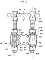
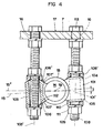
- FIGS. 3 and 4 are partial sections along line III-III of FIG. 2, representing the cage 1 in two distinct positions.
- the glasses 101, 102, 103 are connected to the body 10 by ribs not referenced; the assembly 10, 11, 101, 102, 103 can be mechanically welded, but prefer, as already indicated, a molding part.
- Each telescope 101, 102, 103 consists of a cylindrical trunk with a respective axis 101 ′, 102 ′, 103 ′ and has a central bore 104.
- each telescope has a general shape identical to that of the other two.
- a fundamental characteristic resides in the rounded conformation of the lower and upper faces 105, 105 '(bezel 101), 106 and 106' (bezel 102) and 107, 107 '(bezel 103), the usefulness of which will be easily understood later.
- the faces are curved, that is to say convex; the radius of curvature is located inside the telescope, and chosen at the point of intersection between the median plane 15 (fig. 3) and the respective axis 101 ', 102', 103 'of the telescope.
- the same radius of curvature will be chosen.
- the method of fixing the cage 1 will now be shown with reference only, for simplicity, to the bezel 101.
- the end of a threaded rod or a screw 108 passes through the bore 104 of the bezel 101 in part.
- the diameter of the bore 104 is substantially greater than the diameter of the screw 108.
- a nut 109, a lock washer 111 and an intermediate element 110 allow the bezel to be locked, and therefore of the cage 1, by tightening the nuts 109 on the two respective faces of the telescope. It is clear that the surface 112 of the intermediate element 110, directly adjacent to the face 105 respectively 105 ′, must correspond to this face; in other words, the curvature will be identical.
- the screw 108 passes through a bore 16 made in the auxiliary element, in this case the plate 7.
- the screw 108 is made integral with the plate 7 by the action of the screw head 113 s' pressing on the upper face 17 of the plate 7 and the lock nut 109 '.
- a lock washer 111 ', placed between the underside 18 of the plate 7 and the nut 109', will provide a better guarantee of blocking.
- Other similar fixing means can be used.
- the plate 7 is integral with one or more members of the vehicle, as has already been said above.
- the cage 1 thus designed will ideally allow the snow chain device to be positioned before it is definitively locked (fig. 4): firstly, the device is put in place approximately, that is to say say that it will be ensured that the caster 4, in the working position, therefore placed against the inner flank of the wheel 6 of the vehicle, is situated in a plane approaching the ideal predetermined plane.
- a second step we will proceed to the fine positioning and thereby, to the final adjustment of the wheel in the aforementioned plane. For this, act on the fixing nuts 109 of the glasses, so as to modify the orientation of the median plane 15 relative to a horizontal plane (for example the horizontal plane 15 ") and, correlatively, that of the plane of the caster 4 When the ideal position is reached, the cage 1 will be blocked by tightening, each time nuts 109 on the respective upper and lower faces of the glasses.
- the triangular suspension 101 ', 102', 103 'of the cage 1 on the other hand, the dimensioning of the bore 104, as for its diameter, relative to the diameter of the screw 108, thirdly, the cage 1, respectively the median plane 15, can be "tilted” by an angle ⁇ , in all radial directions with respect to a horizontal plane, for example 15 "(fig. 4).
- a triangle of edges 31, 32, 33 is shown in thin line.
- This triangle is located in the median plane 15, its vertices are formed by the intersections of this plane with the axes 101 ', 102' and 103 '.
- the "tilting" of the cage 1, that is to say the positioning of the latter Ci, can be obtained in several ways. One can for example suppose that one must only act on the telescope 101, by making it mount er or descend, as necessary, using the screw-nut assembly 108, 109, and that one does not wish to vary the position of the glasses 102 and 103, in this case, (of course, the nuts 109 glasses 102 and 103 being just loose), cage 1, resp. the median plane 15 materialized by the triangle 31, 32, 33, will rotate around the axis 31, the glasses 102, 103 fulfilling the role of ball joints.
- the plane 15 can switch around the axes 32 or 33.
- the median plane 15, that is to say the triangle 31, 32, 33 will be able to rotate in all directions around the horizontal. All these planes, whatever their orientations, will pass through a point 19, which is the barycenter of the triangle 31, 32, 33 (fig. 2).
- this point can itself move in height, parallel to the axes 101 ', 102', 103 '.
- this point 19 may be on the longitudinal axis 9, as shown in FIG . 4.
- the said angle ⁇ may vary within a interval from 0 ° to 5 ° approximately.
- the auxiliary snow chain device provided with a positioning and fixing device as described can be mounted on all types of vehicle.
- a pivot arm will be adopted, the length of which will be less than that which is provided for arms mounted on heavy vehicles.
- the diameter of the fixing screws, as well as the corresponding washers will be adapted. We can thus choose screws with a diameter of 12 mm for example.
- the present invention optimally responds to all the problems set out in the introduction. It truly combines the precision of the positioning of the snow chain device and thereby that of the adjustment of the caster in the ideal plane, the reliability of the fixing, the ease of assembly, the rationality of the construction.
Landscapes
- Engineering & Computer Science (AREA)
- Mechanical Engineering (AREA)
- Vehicle Body Suspensions (AREA)
- Automatic Cycles, And Cycles In General (AREA)
- Axle Suspensions And Sidecars For Cycles (AREA)
- Steering-Linkage Mechanisms And Four-Wheel Steering (AREA)
Claims (7)
- Vorrichtung zum Ein- und Feststellen einer Hilfs-Gleitschutzkette, deren Anordnung unter einem Kraftfahrzeug vorgesehen ist, welche Vorrichtung ein Gestell (1) und einen Schwenkarm (3), dessen eines Ende an den genannten Antriebsmitteln befestigt ist und an dessen anderem Ende eine Rolle (4) vorgesehen ist, welche die Enden der Ketten (5) trägt, enthält, wobei der genannte Arm eine freie Position und eine Eingriffsposition einnehmen kann, bei welcher Eingriffsposition sich die Rolle auf der inneren Flanke des Rades (6) des Fahrzeuges abstützt und in einer bezüglich des genannten Rades genau festgelegten Ebene liegen muss, und das Gestell (1), welches eine allgemeine in longitudinaler Achse sich erstreckende Form aufweist, Aufhängungspunkte (101, 102, 103) umfasst, wovon jeder eine bestimmte Beschaffenheit hat, welche jede mit einem oder mehreren Blockierorganen und Befestigungsorganen (108, 109, 110, 111) zusammenwirken, und gleichzeitig sowohl die direkte oder indirekte Befestigung und die Einstellung der Schneekette unter dem Fahrzeug, wie auch die Einstellung der Rolle in der vorbestimmten Ebene ermöglicht, dadurch gekennzeichnet, dass das Gestell (1) Antriebsmittel für den Schwenkarm (3) aufweist, und dass die Aufhängepunkte, wovon drei vorgesehen sind, abwechselnd beidseits der longitudinalen Achse (9) angeordnet sind, und jeder die Form einer mit einer Bohrung (104) versehenen Lasche aufweist, wobei die Achsen (101', 102', 103') der genannten Bohrungen rechtwinklig zur longitudinalen Achse (9) und bevorzugt parallel zueinander stehen, und der Durchmesser der Bohrung (104) jeder Lasche bezüglich des Durchmessers des mit Gewinde versehenen Elementes (108) so gewählt ist, dass die mittlere Ebene (15) des Gestelles in allen radialen Richtungen bezüglich einer horizontalen Ebene um einen Winkel β kippbar ist.
- Vorrichtung nach Anspruch 1, dadurch gekennzeichnet, dass eine (101) der drei Laschen partiell im Bereich der mittleren Ebene (15') und auf einer Seite und senkrecht zur longitudinalen Achse (9) angeordnet ist, während die beiden anderen Laschen (102, 103) auf der anderen Seite der longitudinalen Achse angeordnet sind, eine am vorderen Ende, die andere am hinteren Ende des Gestelles (1).
- Vorrichtung nach einem der Ansprüche 1 oder 2, dadurch gekennzeichnet, dass jeder der oberen und unteren Bereiche (105, 105'; 106, 106'; 107, 107') der Laschen (101, 102, 103) eine abgerundete Form aufweist, wobei die Oberflächen konkav, konvex oder abwechslungsweise konkav/konvex sind.
- Vorrichtung nach Anspruch 3, dadurch gekennzeichnet, dass jedes Befestigungs- und Blockierorgan, welches mit der entsprechenden Lasche zusammenwirkt, aus einem mit Gewinde versehenen Element (108) besteht, welches mit seinem oberen Bereich direkt oder durch Hilfsmittel am Fahrzeug befestigt ist, und welches in seinem unteren Bereich die Bohrung (104) der Lasche sowie die Blockierelemente (109, 110, 111) durchdringt, welche auf die obere und untere Fläche der Lasche festgezogen sind.
- Vorrichtung nach Anspruch 4, dadurch gekennzeichnet, dass die Blockierelemente beiderseits der Lasche jedesmal aus einer Schraubenmutter (109), einer federnden Unterlagscheibe (111) und mindestens einem eingeschobenen Element (110), dessen Form der Oberfläche (112), die der oberen und unteren Fläche der Lasche benachbart ist, der konkaven oder konvexen Form der entsprechenden benachbarten Flächen der Lasche entsprechen, bestehen.
- Vorrichtung nach Anspruch 5, dadurch gekennzeichnet, dass das Gestell (1) sowie die Befestigungs- und Blockierelemente des genannten Gestells über mindestens ein Hilfselement (7) am Fahrzeug befestigt sind.
- Vorrichtung nach Anspruch 6, dadurch gekennzeichnet, dass das genannte Hilfselement eine starre Platte (7) ist.
Priority Applications (1)
| Application Number | Priority Date | Filing Date | Title |
|---|---|---|---|
| AT89810205T ATE88418T1 (de) | 1988-03-25 | 1989-03-15 | Vorrichtung zum ein- und feststellen einer hilfs- gleitschutzkette fuer kraftfahrzeuge. |
Applications Claiming Priority (2)
| Application Number | Priority Date | Filing Date | Title |
|---|---|---|---|
| CH1136/88 | 1988-03-25 | ||
| CH113688 | 1988-03-25 |
Publications (2)
| Publication Number | Publication Date |
|---|---|
| EP0334810A1 EP0334810A1 (de) | 1989-09-27 |
| EP0334810B1 true EP0334810B1 (de) | 1993-04-21 |
Family
ID=4203330
Family Applications (1)
| Application Number | Title | Priority Date | Filing Date |
|---|---|---|---|
| EP89810205A Expired - Lifetime EP0334810B1 (de) | 1988-03-25 | 1989-03-15 | Vorrichtung zum Ein- und Feststellen einer Hilfs-Gleitschutzkette für Kraftfahrzeuge |
Country Status (7)
| Country | Link |
|---|---|
| US (1) | US4901809A (de) |
| EP (1) | EP0334810B1 (de) |
| JP (1) | JPH0228008A (de) |
| CN (1) | CN1037109A (de) |
| AT (1) | ATE88418T1 (de) |
| CA (1) | CA1322150C (de) |
| DE (1) | DE68906065D1 (de) |
Families Citing this family (11)
| Publication number | Priority date | Publication date | Assignee | Title |
|---|---|---|---|---|
| SE467456B (sv) * | 1988-10-20 | 1992-07-20 | Onspot Ab | Armlagring vid slirskydd |
| US5076379A (en) * | 1990-11-19 | 1991-12-31 | Bahr William T | Mechanism for translation of linear motion to rotary motion |
| SE511257C2 (sv) | 1998-01-29 | 1999-09-06 | Vbg Prod Ab | Manöveranordning |
| US6651783B1 (en) | 2000-08-28 | 2003-11-25 | John H. Atkinson, Jr. | Adjustable mounting assembly for a rapidly-deployable ice chain system for wheeled vehicles |
| KR100507138B1 (ko) * | 2001-12-26 | 2005-08-09 | 현대자동차주식회사 | 차량의 스노우체인 구동제어 장치 |
| DE102004016154B4 (de) * | 2003-04-02 | 2009-04-23 | Irwin Industrial Tool Co., Freeport | Schnell einstellbare Zange |
| US7506729B2 (en) * | 2004-01-13 | 2009-03-24 | Smith Patents, Llc | Torque-limited electric servo system for deploying a vehicle snow chain traction system |
| US7118130B2 (en) * | 2004-01-23 | 2006-10-10 | Onspot Of North America, Inc. | Anti-skid tire chain device |
| US20110146866A1 (en) * | 2009-12-19 | 2011-06-23 | Samad Jafari Valilou | Automatic tire chain system |
| US10675914B2 (en) * | 2017-12-20 | 2020-06-09 | Dusawn Holdings LLC | Tire chains apparatus |
| CN115157928B (zh) * | 2022-09-07 | 2023-03-21 | 之江实验室 | 一种全自动车载防滑装置 |
Family Cites Families (7)
| Publication number | Priority date | Publication date | Assignee | Title |
|---|---|---|---|---|
| US2283948A (en) * | 1941-04-09 | 1942-05-26 | Herbert N Ridgway | Automobile traction device |
| US2790514A (en) * | 1956-03-12 | 1957-04-30 | Robinson Luther | Anti-skid apparatus for vehicles |
| US3658158A (en) * | 1970-02-17 | 1972-04-25 | Chauncey P Saupp | Anti-skid device for motor vehicles |
| SE447811B (sv) * | 1985-03-01 | 1986-12-15 | Onspot Ab | Slirskydd |
| EP0195973B1 (de) * | 1985-03-14 | 1990-01-17 | Gerd Schulz Fahrzeug- und Container-Technik | Schleuderkettenaggregat für Kraftfahrzeuge |
| EP0209484B1 (de) * | 1985-07-19 | 1990-07-18 | RUD-Kettenfabrik Rieger & Dietz GmbH u. Co. | Gleitschutzvorrichtung für Kraftfahrzeuge |
| SE452969B (sv) * | 1986-07-03 | 1988-01-04 | Onspot Ab | Anordning vid slirskydd |
-
1989
- 1989-03-15 EP EP89810205A patent/EP0334810B1/de not_active Expired - Lifetime
- 1989-03-15 AT AT89810205T patent/ATE88418T1/de not_active IP Right Cessation
- 1989-03-15 DE DE8989810205T patent/DE68906065D1/de not_active Expired - Lifetime
- 1989-03-17 US US07/325,265 patent/US4901809A/en not_active Expired - Fee Related
- 1989-03-23 CA CA000594573A patent/CA1322150C/fr not_active Expired - Fee Related
- 1989-03-23 CN CN89101762A patent/CN1037109A/zh active Pending
- 1989-03-27 JP JP1076374A patent/JPH0228008A/ja active Pending
Also Published As
| Publication number | Publication date |
|---|---|
| CA1322150C (fr) | 1993-09-14 |
| DE68906065D1 (de) | 1993-05-27 |
| CN1037109A (zh) | 1989-11-15 |
| ATE88418T1 (de) | 1993-05-15 |
| JPH0228008A (ja) | 1990-01-30 |
| EP0334810A1 (de) | 1989-09-27 |
| US4901809A (en) | 1990-02-20 |
Similar Documents
| Publication | Publication Date | Title |
|---|---|---|
| FR2624452A1 (fr) | Organe de fixation et d'articulation notamment pour dispositif de reglage d'un element optique en particulier pour projecteur de vehicule automobile | |
| EP0300538B1 (de) | Vorrichtung zur positiven Befestigung einer Radzierblende an einer Kraftfahrzeugradfelge | |
| EP0810944A1 (de) | Schnellspannachse für ein fahrrad | |
| EP2814640B1 (de) | Werkzeug zum montieren einer aufhängungs-blattfeder an den fahrzeugrahmen und den radträger einer fahrzeugachse eines kraftfahrzeugs und zu dessen demontage | |
| FR2495093A1 (fr) | Motocyclette a suspension arriere perfectionnee | |
| EP0334810A1 (de) | Vorrichtung zum Ein- und Feststellen einer Hilfs-Gleitschutzkette für Kraftfahrzeuge | |
| EP0133389B1 (de) | Scheibenbremse mit abnehmbarem Verstärkungssattelarm | |
| FR2845460A1 (fr) | Projecteur d'eclairage de vehicule automobile comportant un element d'articulation en appui sur le boitier | |
| EP0641889B1 (de) | Sockel für einen Pfosten | |
| EP2004429A1 (de) | Hinterachse eines fahrzeuges, im besonderen eines kraftfahrzeuges, sowie mit dieser hinterachse ausgestattetes fahrzeug | |
| EP0443910A1 (de) | Sperrvorrichtung eines tubulären Organs, insbesondere einer Kraftfahrzeuglenksäule | |
| FR3064590A1 (fr) | Vehicule pendulaire a organes de blocage d'inclinaison | |
| FR2843364A1 (fr) | Pedalier pour cycle avec un bras de levier optimise | |
| FR2574877A1 (fr) | Dispositif de fixation et son procede de montage | |
| EP0269538A1 (de) | Richtarm und Einrichtung zum Richten von verformten Karosserien oder anderen Fahrzeugteilen | |
| FR2564521A1 (fr) | Perfectionnements a des stores a l'italienne | |
| FR2573363A1 (fr) | Articulation elastique de bras oscillant, notamment pour des bras oscillants d'essieux de vehicules utilitaires | |
| FR2528790A1 (fr) | Mecanisme de suspension de roue de vehicule avec adaptation a la charge | |
| FR3099089A1 (fr) | Palier et pièce de réglage pour train multi-bras | |
| FR2720845A1 (fr) | Vis de réglage. | |
| FR2525536A1 (de) | ||
| FR2736032A1 (fr) | Potence de bicyclette | |
| FR2651165A1 (fr) | Dispositif a pince pour le serrage du bas de caisse d'un vehicule automobile. | |
| EP0253708B1 (de) | Hinterachse mit passiver Wirkung für Kraftfahrzeuge und Kraftfahrzeuge, ausgerüstet mit solch einer Hinterachse | |
| FR2711101A1 (fr) | Pièce de montage de la tige de sortie à extrémité sphérique d'un correcteur sur un réflecteur pour projecteur de véhicule automobile. |
Legal Events
| Date | Code | Title | Description |
|---|---|---|---|
| PUAI | Public reference made under article 153(3) epc to a published international application that has entered the european phase |
Free format text: ORIGINAL CODE: 0009012 |
|
| AK | Designated contracting states |
Kind code of ref document: A1 Designated state(s): AT BE CH DE ES FR GB GR IT LI LU NL SE |
|
| 17P | Request for examination filed |
Effective date: 19900319 |
|
| 17Q | First examination report despatched |
Effective date: 19910905 |
|
| GRAA | (expected) grant |
Free format text: ORIGINAL CODE: 0009210 |
|
| AK | Designated contracting states |
Kind code of ref document: B1 Designated state(s): AT BE CH DE ES FR GB GR IT LI LU NL SE |
|
| PG25 | Lapsed in a contracting state [announced via postgrant information from national office to epo] |
Ref country code: IT Free format text: LAPSE BECAUSE OF FAILURE TO SUBMIT A TRANSLATION OF THE DESCRIPTION OR TO PAY THE FEE WITHIN THE PRE;WARNING: LAPSES OF ITALIAN PATENTS WITH EFFECTIVE DATE BEFORE 2007 MAY HAVE OCCURRED AT ANY TIME BEFORE 2007. THE CORRECT EFFECTIVE DATE MAY BE DIFFERENT FROM THE ONE RECORDED.SCRIBED TIME-LIMIT Effective date: 19930421 Ref country code: GR Free format text: LAPSE BECAUSE OF FAILURE TO SUBMIT A TRANSLATION OF THE DESCRIPTION OR TO PAY THE FEE WITHIN THE PRESCRIBED TIME-LIMIT Effective date: 19930421 Ref country code: DE Effective date: 19930421 Ref country code: NL Effective date: 19930421 Ref country code: ES Free format text: THE PATENT HAS BEEN ANNULLED BY A DECISION OF A NATIONAL AUTHORITY Effective date: 19930421 Ref country code: SE Effective date: 19930421 Ref country code: GB Effective date: 19930421 Ref country code: AT Effective date: 19930421 |
|
| REF | Corresponds to: |
Ref document number: 88418 Country of ref document: AT Date of ref document: 19930515 Kind code of ref document: T |
|
| REF | Corresponds to: |
Ref document number: 68906065 Country of ref document: DE Date of ref document: 19930527 |
|
| NLV1 | Nl: lapsed or annulled due to failure to fulfill the requirements of art. 29p and 29m of the patents act | ||
| GBV | Gb: ep patent (uk) treated as always having been void in accordance with gb section 77(7)/1977 [no translation filed] |
Effective date: 19930421 |
|
| PLBE | No opposition filed within time limit |
Free format text: ORIGINAL CODE: 0009261 |
|
| STAA | Information on the status of an ep patent application or granted ep patent |
Free format text: STATUS: NO OPPOSITION FILED WITHIN TIME LIMIT |
|
| PG25 | Lapsed in a contracting state [announced via postgrant information from national office to epo] |
Ref country code: LU Free format text: LAPSE BECAUSE OF NON-PAYMENT OF DUE FEES Effective date: 19940331 Ref country code: BE Effective date: 19940331 |
|
| 26N | No opposition filed | ||
| BERE | Be: lapsed |
Owner name: S.A. BEKA ST-AUBIN Effective date: 19940331 |
|
| PG25 | Lapsed in a contracting state [announced via postgrant information from national office to epo] |
Ref country code: FR Effective date: 19941130 |
|
| REG | Reference to a national code |
Ref country code: FR Ref legal event code: ST |
|
| PGFP | Annual fee paid to national office [announced via postgrant information from national office to epo] |
Ref country code: CH Payment date: 19990819 Year of fee payment: 11 |
|
| PG25 | Lapsed in a contracting state [announced via postgrant information from national office to epo] |
Ref country code: CH Free format text: LAPSE BECAUSE OF NON-PAYMENT OF DUE FEES Effective date: 20000331 Ref country code: LI Free format text: LAPSE BECAUSE OF NON-PAYMENT OF DUE FEES Effective date: 20000331 |
|
| REG | Reference to a national code |
Ref country code: CH Ref legal event code: PL |