EP0334806B1 - Gesteinsbohrkrone - Google Patents
Gesteinsbohrkrone Download PDFInfo
- Publication number
- EP0334806B1 EP0334806B1 EP89810149A EP89810149A EP0334806B1 EP 0334806 B1 EP0334806 B1 EP 0334806B1 EP 89810149 A EP89810149 A EP 89810149A EP 89810149 A EP89810149 A EP 89810149A EP 0334806 B1 EP0334806 B1 EP 0334806B1
- Authority
- EP
- European Patent Office
- Prior art keywords
- area
- core bit
- axially
- drill
- cutter head
- Prior art date
- Legal status (The legal status is an assumption and is not a legal conclusion. Google has not performed a legal analysis and makes no representation as to the accuracy of the status listed.)
- Expired - Lifetime
Links
- 239000011435 rock Substances 0.000 title claims abstract description 14
- 238000005553 drilling Methods 0.000 claims abstract description 32
- 238000005520 cutting process Methods 0.000 claims abstract description 27
- 239000002699 waste material Substances 0.000 claims 1
- 238000004519 manufacturing process Methods 0.000 description 5
- 238000000034 method Methods 0.000 description 5
- 238000001125 extrusion Methods 0.000 description 2
- 239000000463 material Substances 0.000 description 2
- 239000000758 substrate Substances 0.000 description 2
- 230000005540 biological transmission Effects 0.000 description 1
- 239000010432 diamond Substances 0.000 description 1
- 239000000428 dust Substances 0.000 description 1
- 230000000694 effects Effects 0.000 description 1
- 239000002360 explosive Substances 0.000 description 1
- 238000005242 forging Methods 0.000 description 1
- 238000003754 machining Methods 0.000 description 1
- 239000011159 matrix material Substances 0.000 description 1
- 229910052751 metal Inorganic materials 0.000 description 1
- 239000002184 metal Substances 0.000 description 1
- 238000010079 rubber tapping Methods 0.000 description 1
- 238000007493 shaping process Methods 0.000 description 1
- 230000035939 shock Effects 0.000 description 1
- WFKWXMTUELFFGS-UHFFFAOYSA-N tungsten Chemical compound [W] WFKWXMTUELFFGS-UHFFFAOYSA-N 0.000 description 1
- 229910052721 tungsten Inorganic materials 0.000 description 1
- 239000010937 tungsten Substances 0.000 description 1
Images
Classifications
-
- B—PERFORMING OPERATIONS; TRANSPORTING
- B28—WORKING CEMENT, CLAY, OR STONE
- B28D—WORKING STONE OR STONE-LIKE MATERIALS
- B28D1/00—Working stone or stone-like materials, e.g. brick, concrete or glass, not provided for elsewhere; Machines, devices, tools therefor
- B28D1/02—Working stone or stone-like materials, e.g. brick, concrete or glass, not provided for elsewhere; Machines, devices, tools therefor by sawing
- B28D1/04—Working stone or stone-like materials, e.g. brick, concrete or glass, not provided for elsewhere; Machines, devices, tools therefor by sawing with circular or cylindrical saw-blades or saw-discs
- B28D1/041—Working stone or stone-like materials, e.g. brick, concrete or glass, not provided for elsewhere; Machines, devices, tools therefor by sawing with circular or cylindrical saw-blades or saw-discs with cylinder saws, e.g. trepanning; saw cylinders, e.g. having their cutting rim equipped with abrasive particles
-
- E—FIXED CONSTRUCTIONS
- E21—EARTH OR ROCK DRILLING; MINING
- E21B—EARTH OR ROCK DRILLING; OBTAINING OIL, GAS, WATER, SOLUBLE OR MELTABLE MATERIALS OR A SLURRY OF MINERALS FROM WELLS
- E21B10/00—Drill bits
- E21B10/02—Core bits
- E21B10/04—Core bits with core destroying means
-
- E—FIXED CONSTRUCTIONS
- E21—EARTH OR ROCK DRILLING; MINING
- E21B—EARTH OR ROCK DRILLING; OBTAINING OIL, GAS, WATER, SOLUBLE OR MELTABLE MATERIALS OR A SLURRY OF MINERALS FROM WELLS
- E21B10/00—Drill bits
- E21B10/36—Percussion drill bits
- E21B10/40—Percussion drill bits with leading portion
Definitions
- the invention relates to a rock drilling tool with a drill bit, the drill bit having an area widening in the feed direction in the inner and outer diameter, which is adjoined in the feed direction by a cylindrical area with a constant inner and outer diameter, the end face of which is provided with cutting bodies along the circumference, which project axially and radially beyond the cylindrical area and the drill bit is provided with a centering drill which projects axially beyond it, and has at least one essentially axially extending passage opening for the cuttings which is open to the outer contour.
- Rock drilling tools known from DE-A-2 856 205 have a shank and a bell-shaped drilling head at the front end.
- the drill head is provided with cutting pins on its face.
- the drill head has grooves extending from the circumference, which serve for the passage of the cuttings. After the guide length of this drill head is short, it is not possible to produce precise bores, for example for receiving mechanical anchors. Due to the complex shape, these drilling tools can only be manufactured by forging and subsequent machining, which leads to high manufacturing costs.
- a bell-like chisel tool can be seen from DE-PS 2 928 445, which is used together with an impact-emitting device.
- This tool is at least partially tapered on the outside and inside in the feed direction.
- the front end of the tool in the setting direction is designed as a ring cutter.
- the tool also has through-openings which are inclined to the longitudinal axis and lead from the inside to the outside and which serve to discharge the cuttings which are broken and crushed by the conical inner shape. Due to the design for purely striking operation, no requirements regarding guidance are made on this tool used for earth drilling.
- US-A-4,101,238 relates to a carbide-tipped drill bit with a replaceable center drill.
- the through openings arranged in a central position in the axial direction form suction channels for the drilling dust which arises when the substrate is being worked on.
- the drill cores in the drill bit must be removed again and again.
- Tungsten carbide-tipped drill bits have the disadvantage that the cutting edges are subject to different wear towards their outer ends.
- the manufacture of drill bits designed in this way, as are known from US Pat. No. 4,101,238, is extremely difficult. Due to the large, essentially linear contact surface, the explosive effect of the drill bit caused by the impact is greatly reduced. Due to the large contact surface, the cuttings are crushed more. This unnecessarily dissipates energy that could be used more effectively for drilling progress. The overall drilling progress is reduced.
- the invention has for its object to provide a rock drilling tool that is economical to manufacture, is suitable for removing cuttings from the inside of the rock drilling tool and for creating deeper holes with a precise geometric shape.
- this is achieved in that the passage opening essentially extends through the entire length of the region of the drill bit which widens in the inner and outer diameter and in that the cutting bodies are designed in the form of a pin.
- the core that remains when working on the subsoil is broken when it hits the conical area, so that the resulting cuttings can escape through the through hole from the drill bit and into the area of a transport helix that adjoins the back of the drill bit.
- Wear-resistant elements can be arranged in the conical overrun area.
- An annular groove is cut out by the cutting bodies projecting both radially and axially over the cylindrical region when working with the drilling tool according to the invention.
- the crown body With axially protruding cutting bodies, the crown body hardly comes into direct contact with the surface. On the one hand, this enables good removal of the cuttings and, on the other hand, prevents wear on the crown body.
- the cutting bodies can protrude radially both outwards and inwards. This enables free cutting and prevents the cylindrical area of the crown body from touching the borehole wall.
- the cutting bodies are expediently designed in the form of a pin. Such cutting bodies can be accommodated in bores in the drill bit and are therefore precisely positioned, whereby they are also simple to manufacture and can under certain circumstances be replaced by the user himself.
- the cutting bodies arranged on the end face serve to process the subsurface.
- the drill bit For the tapping process as well as for the continuation of the bore, the drill bit is provided with a centering drill that projects axially above it. At the start of the drilling process, the center drill comes into contact with the surface. The drill bit then engages on the subsurface. The center drill prevents the drilling tool from running sideways. The center drill is subject to a relatively high degree of wear and should therefore be exchangeable, since the tool is only partially functional in the event of a failure.
- the shaping proposed according to the invention enables economical production, in particular by extrusion.
- the decisive factor here is the fact that there are no major jumps in the material thickness. Due to the conical design in connection with the cylindrical area, ideal conditions for an extrusion process are also given from the point of view of the material flow. It also enables better shock transmission.
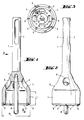
- the rock drilling tool shown in FIGS. 1 to 3 essentially consists of a shank 1 which is provided with longitudinal grooves 2 in its rear end region. These longitudinal grooves 2 are used for the axial mounting and the rotary driving of the drilling tool.
- the shaft 1 is provided with a conical region 3 that widens in the feed direction and has an inner and outer diameter that widens in the feed direction.
- a cylindrical region 4 adjoins the conical region 3.
- the length L of this cylindrical region 4 is approximately 0.2 to 3 times the outer diameter D.
- the front end of the cylindrical region 4 is designed as an annular cutting edge 5.
- the conical region 3 is provided with through openings 6 which serve to discharge the cuttings formed in the interior of the drill bit.
- the inside of the drill bit is provided with a receiving bore 7 for a centering drill 8 axially projecting beyond the drill bit.
- a centering drill 8 axially projecting beyond the drill bit.
- the drill bit is pin-shaped in the area of the cutting edge 5
- These cutting bodies 9 are preferably hard metal pins. However, these cutting bodies 9 can also be plate-shaped or consist of synthetic diamonds embedded in a matrix.
Landscapes
- Engineering & Computer Science (AREA)
- Mining & Mineral Resources (AREA)
- Geology (AREA)
- Life Sciences & Earth Sciences (AREA)
- Mechanical Engineering (AREA)
- Environmental & Geological Engineering (AREA)
- Fluid Mechanics (AREA)
- Physics & Mathematics (AREA)
- General Life Sciences & Earth Sciences (AREA)
- Geochemistry & Mineralogy (AREA)
- Earth Drilling (AREA)
- Pharmaceuticals Containing Other Organic And Inorganic Compounds (AREA)
- Medicines Containing Material From Animals Or Micro-Organisms (AREA)
- Drilling And Exploitation, And Mining Machines And Methods (AREA)
- Processing Of Stones Or Stones Resemblance Materials (AREA)
Description
- Die Erfindung betrifft ein Gesteinsbohrwerkzeug mit Bohrkrone, wobei die Bohrkrone einen sich in Vorschubrichtung im Innen- und Aussendurchmesser erweiternden Bereich aufweist, an den sich in Vorschubrichtung ein zylindrischer Bereich mit konstantem Innen- und Aussendurchmesser anschliesst, dessen Stirnseite entlang des Umfanges mit Schneidkörpern versehen ist, die den zylindrischen Bereich axial und radial überragen und wobei die Bohrkrone mit einem, diese axial überragenden Zentrierbohrer versehen ist, sowie wenigstens eine im wesentlichen axial verlaufende, zur Aussenkontur hin offene Durchtrittsöffnung für das Bohrklein aufweist.
- Aus der DE-A-2 856 205 bekannte Gesteinsbohrwerkzeuge weisen einen Schaft und am vorderen Ende einen glockenförmig ausgebildeten Bohrkopf auf. Der Bohrkopf ist an seiner Stirnseite mit Schneidstiften versehen. Ausserdem weist der Bohrkopf vom Umfang ausgehende Nuten auf, welche dem Durchtritt des Bohrkleins dienen. Nachdem die Führungslänge dieses Bohrkopfes gering ist, lassen sich genaue Bohrungen, beispielsweise zur Aufnahme von mechanisch zu spreizenden Dübeln, nicht herstellen. Durch die aufwendige Formgebung ist eine Herstellung dieser Bohrwerkzeuge nur durch Schmieden und anschliessende spanabhebende Bearbeitung möglich, was zu hohen Herstellkosten führt.
- Aus der DE-A-3 049 135 sind weitere Gesteinsbohrwerkzeuge bekannt, deren Aussendurchmesser vom Schaft her in Vorschubrichtung konisch zunimmt. Wie die DE-A-3 049 135 weisen auch die aus den bekannten Druckschriften AT-A-360 734 und US-A-2 334 453 Bohrwerkzeuge in Form einer wenigstens teilweise geschlossenen Glocke auf. Die Bohrtiefe dieser Bohrwerkzeuge ist dadurch begrenzt. Falls mit diesen Bohrwerkzeugen Durchbrüche in Wänden mit grösserer Wandstärke hergestellt werden sollen, so muss dies in mehreren Etappen erfolgen, weil jeweils nach einer Etappe der Bohrkern entfernt werden muss. Die Entleerungslöcher der AT-A-360 734 und der US-A-2 334 453 dienen der Enthiftung des Hohlraumes in der Glocke und dem Abtransport des abgebauten Gesteins.
- Neben diesen bekannten Gesteinsbohrwerkzeugen ist aus der DE-PS 2 928 445 ein glockenartiges Meisselwerkzeug ersichtlich, das zusammen mit einem Schläge abgebenden Gerät verwendet wird. Dieses Werkzeug ist an seiner Aussen- und Innenseite zumindest teilweise in Vorschubrichtung konisch erweitert. Das in Setzrichtung vordere Ende des Werkzeuges ist als Ringschneide ausgebildet. Das Werkzeug weist ferner zur Längsachse geneigt angeordnete, von der Innen- zur Aussenseite führende Durchtrittsöffnungen auf, die der Abfuhr des Bohrkleins dienen, das durch die konische Innenform gebrochen und zerkleinert wird. Durch die Auslegung auf rein schlagenden Betrieb werden an dieses zum Erdbohren verwendete Werkzeug keine Anforderungen hinsichtlich Führung gestellt.
- Die US-A-4,101,238 betrifft eine hartmetallbestückte Bohrkrone mit auswechselbarem Zentrierbohrer. Die in zentraler Lage in axialer Richtung angeordneten Durchtrittsöffnungen bilden Absaugkanäle für den beim Bearbeiten des Untergrundes entstehenden Bohrstaub. Bei der Erstellung von Bohrungen in Wänden mit grösserer Wandstärke müssen die sich in der Bohrkrone befindlichen Bohrkerne immer wieder entfernt werden.
- Hartmetallbestückte Bohrkronen weisen den Nachteil auf, dass die Schneiden nach ihren äusseren Enden hin einem unterschiedlichen Verschleiss unterworfen sind. Die Fertigung derart ausgebildeter Bohrkronen, wie sie aus der US-A-4 101 238 bekannt sind, ist ausserordentlich schwierig. Durch die infolge der grossen, im wesentlichen linienförmigen Auflagefläche wird die durch die Schlagwirkung hervorgerufene Sprengwirkung der Bohrkrone stark herabgesetzt. Durch die grosse Auflagefläche wird das Bohrklein stärker zerkleinert. Dadurch wird unnützerweise Energie abgebaut, die für den Bohrfortschritt sinnvoller genützt werden könnte. Der allgemeine Bohrfortschritt wird dadurch geringer.
- Der Erfindung liegt die Aufgabe zugrunde, ein Gesteinsbohrwerkzeug zu schaffen, das sich wirtschaftlich herstellen lässt, zur Abfuhr von Bohrklein aus dem Inneren des Gesteinsbohrwerkzeuges und zur Schaffung tieferer Bohrlöcher mit genauer geometrischer Form geeignet ist.
- Gemäss der Erfindung wird dies dadurch erreicht, dass die Durchtrittsöffnung im wesentlichen die gesamte Länge des den sich im Innen- und Aussendurchmesser erweiternden Bereiches der Bohrkrone durchsetzt und dass die Schneidkörper stiftförmig ausgebildet sind.
- Der beim Bearbeiten des Untergrundes stehenbleibende Kern wird beim Auflaufen auf den konischen Bereich gebrochen, so dass das entstehende Bohrklein durch die Durchtrittsöffnung aus der Bohrkrone entweichen kann und in den Bereich einer gegebenenfalls sich rückseitig an die Bohrkrone anschliessenden Transportwendel gelangt. Im konischen Auflaufbereich können verschleissfeste Elemente angeordnet werden.
- Durch die den zylindrischen Bereich sowohl radial als auch axial überragenden Schneidkörper wird beim Arbeiten mit dem erfindungsgemässen Bohrwerkzeug eine Ringnut herausgeschnitten. Der Kronenkörper kommt bei axial überragenden Schneidkörpern kaum in direkte Berührung mit dem Untergrund. Dies ermöglicht einerseits eine gute Abfuhr des Bohrkleins und verhindert andererseits einen Verschleiss des Kronenkörpers. Das radial Überragen der Schneidkörper kann sowohl nach aussen als auch nach innen erfolgen. Dies ermöglicht ein Freischneiden und verhindert eine Berührung des zylindrischen Bereiches des Kronenkörpers mit der Bohrlochwandung.
- Zweckmässigerweise sind die Schneidkörper stiftförmig ausgebildet. Solche Schneidkörper können in Bohrungen der Bohrkrone aufgenommen werden und sind dadurch in der Lage genau positioniert, wobei sie zudem in der Herstellung einfach sind und unter Umständen vom Anwender selbst ausgewechselt werden können.
- Der sich in Vorschubrichtung an den Bereich mit sich erweiterndem Innen- und Aussendurchmesser anschliessende zylindrische Bereich schafft eine gute Führung des Bohrwerkzeuges im Bohrloch. Die an der Stirnseite angeordneten Schneidkörper dienen dem Bearbeiten des Untergrundes.
- Für den Anbohrvorgang sowie auch für das Weiterführen der Bohrung ist die Bohrkrone mit einem, diese axial überragenden Zentrierbohrer versehen. Zu Beginn des Bohrvorganges kommt zuerst der Zentrierbohrer mit dem Untergrund in Berührung. Anschliessend gelangt die Bohrkrone am Untergrund in Eingriff. Durch den Zentrierbohrer wird ein seitliches Verlaufen des Bohrwerkzeugs verhindert. Der Zentrierbohrer ist einem relativ hohen Verschleiss unterworfen und sollte daher auswechselbar sein, da das Werkzeug bei einem Ausfall nur noch bedingt funktionstüchtig ist.
- Die erfindungsgemäss vorgeschlagene Formgebung ermöglicht eine wirtschaftliche Herstellung, insbesondere durch Fliesspressen. Massgebend hierzu ist vor allem der Umstand, dass keine grossen Sprünge in den Materialstärken vorhanden sind. Durch die kegelartige Ausbildung in Verbindung mit dem zylindrischen Bereich sind zudem aus der Sicht des Materialflusses ideale Voraussetzungen für ein Fliesspressverfahren gegeben. Ausserdem wird dadurch eine bessere Stossübertragung ermöglicht.
- Die Erfindung soll nachstehend anhand der sie beispielsweise wiedergebenden Zeichnungen näher erläutert werden. Es zeigen:
- Fig. 1
- ein erfindungsgemässes Gesteinsbohrwerkzeug, teilweise im Schnitt dargestellt;
- Fig. 2
- eine Ansicht des in Fig. 1 dargestellten Gesteinsbohrwerkzeuges, in Richtung des Pfeiles A;
- Fig. 3
- eine Ansicht des in Fig. 1 dargestellten Gesteinsbohrwerkzeuges, in Richtung des Pfeiles B.
- Das aus Fig. 1 bis 3 ersichtliche Gesteinsbohrwerkzeug besteht im wesentlichen aus einem Schaft 1, der in seinem rückwärtigen Endbereich mit Längsnuten 2 versehen ist. Diese Längsnuten 2 dienen der axialen Halterung und der Drehmitnahme des Bohrwerkzeuges. Der Schaft 1 ist mit einem sich in Vorschubrichtung erweiternden, konischen Bereich 3 mit sich in Vorschubrichtung erweiterndem Innen- und Aussendurchmesser versehen. An den konischen Bereich 3 schliesst sich ein zylindrischer Bereich 4 an. Die Länge L dieses zylindrischen Bereiches 4 beträgt etwa das 0,2- bis 3-fache des Aussendurchmessers D. Das vordere Ende des zylindrischen Bereiches 4 ist als ringförmige Schneidkante 5 ausgebildet. Der konische Bereich 3 ist mit Durchtrittsöffnungen 6 versehen, welche der Abfuhr des sich im Innern der Bohrkrone bildenden Bohrkleins dienen. Die Bohrkrone ist an ihrer Innenseite mit einer Aufnahmebohrung 7 für einen die Bohrkrone axial überragenden Zentrierbohrer 8 versehen. Zu Beginn des Anbohrvorganges kommt zunächst nur der Zentrierbohrer 8 mit der Oberfläche des zu bearbeitenden Untergrundes in Eingriff. Die Bohrkrone ist im Bereich des Schneidkante 5 mit stiftförmigen Schneidkörpern 9 versehen. Bei diesen Schneidkörpern 9 handelt es sich vorzugsweise um Hartmetallstifte. Diese Schneidkörper 9 können jedoch auch plattenförmig ausgebildet oder aus synthetischen, in eine Matrix eingebetteten Diamanten bestehen.
Claims (1)
- Gesteinsbohrwerkzeug mit Bohrkrone, wobei die Bohrkrone einen sich in Vorschubrichtung im Innen- und Aussendurchmesser erweiternden Bereich (3) aufweist, an den sich in Vorschubrichtung ein zylindrischer Bereich (4) mit konstantem Innen- und Aussendurchmesser an schliesst, dessen Stirnseite entlang des Umfanges mit Schneidkörpern (9) versehen ist, die den zylindrischen Bereich axial und radial überragen und wobei die Bohrkrone mit einem, diese axial überragenden Zentrierbohrer (8) versehen ist, sowie wenigstens eine im wesentlichen axial verlaufende, zur Aussenkontur hin offene Durchtrittsöffnung (6) für das Bohrklein aufweist, dadurch gekennzeichnet, dass die Durchtrittsöffnung (6) im wesentlichen die gesamte Länge des sich im Innen- und Aussendurchmesser erweiternden Bereiches der Bohrkrone durchsetzt und dass die Schneidkörper (9) stiftförmig ausgebildet sind.
Priority Applications (1)
| Application Number | Priority Date | Filing Date | Title |
|---|---|---|---|
| AT89810149T ATE95888T1 (de) | 1988-03-21 | 1989-02-27 | Gesteinsbohrkrone. |
Applications Claiming Priority (2)
| Application Number | Priority Date | Filing Date | Title |
|---|---|---|---|
| DE3809428A DE3809428A1 (de) | 1988-03-21 | 1988-03-21 | Gesteinsbohrkrone |
| DE3809428 | 1988-03-21 |
Publications (2)
| Publication Number | Publication Date |
|---|---|
| EP0334806A1 EP0334806A1 (de) | 1989-09-27 |
| EP0334806B1 true EP0334806B1 (de) | 1993-10-13 |
Family
ID=6350274
Family Applications (1)
| Application Number | Title | Priority Date | Filing Date |
|---|---|---|---|
| EP89810149A Expired - Lifetime EP0334806B1 (de) | 1988-03-21 | 1989-02-27 | Gesteinsbohrkrone |
Country Status (5)
| Country | Link |
|---|---|
| EP (1) | EP0334806B1 (de) |
| JP (1) | JPH01284690A (de) |
| AT (1) | ATE95888T1 (de) |
| DE (2) | DE3809428A1 (de) |
| DK (1) | DK125989A (de) |
Cited By (1)
| Publication number | Priority date | Publication date | Assignee | Title |
|---|---|---|---|---|
| CN103383319A (zh) * | 2012-05-03 | 2013-11-06 | 中国石油化工股份有限公司 | 密闭保型取心岩心保鲜处理结构及其保鲜处理方法 |
Families Citing this family (5)
| Publication number | Priority date | Publication date | Assignee | Title |
|---|---|---|---|---|
| US5279607A (en) * | 1991-05-30 | 1994-01-18 | The State University Of New York | Telemetry capsule and process |
| DE4236553A1 (de) * | 1992-10-29 | 1994-05-05 | Hawera Probst Kg Hartmetall | Gesteinsbohrer |
| DE4301191A1 (de) * | 1993-01-19 | 1994-07-21 | Hawera Probst Kg Hartmetall | Gesteinsbohrwerkzeug |
| CN102134850A (zh) * | 2011-01-08 | 2011-07-27 | 洪子云 | 金钢钻吸土成孔钻头 |
| DE102011090063B4 (de) * | 2011-10-13 | 2024-07-04 | Robert Bosch Gmbh | Hammerbohrkrone |
Family Cites Families (10)
| Publication number | Priority date | Publication date | Assignee | Title |
|---|---|---|---|---|
| US2334453A (en) * | 1942-04-30 | 1943-11-16 | Peter J Swofford | Speed rock bit |
| DE2602238A1 (de) * | 1976-01-22 | 1977-08-04 | Bosch Gmbh Robert | Bohrkrone |
| DE2807198A1 (de) * | 1978-02-20 | 1979-08-30 | Heller Verwaltungsges | Verfahren zum herstellen einer bohrkrone und nach dem verfahren hergestellte bohrkrone |
| DE2856205A1 (de) * | 1978-12-27 | 1980-07-10 | Hilti Ag | Gesteinsbohrer |
| DE2913501A1 (de) * | 1979-04-04 | 1980-10-16 | Bosch Gmbh Robert | Hohlbohrer mit bohrkrone |
| US4280573A (en) * | 1979-06-13 | 1981-07-28 | Sudnishnikov Boris V | Rock-breaking tool for percussive-action machines |
| AT360734B (de) * | 1979-08-17 | 1981-01-26 | Swarovski Tyrolit Schleif | Hohlbohrer |
| DE3049135A1 (de) * | 1980-12-24 | 1982-07-15 | Hawera Probst Gmbh + Co, 7980 Ravensburg | Bohrer, insbesondere gesteinsbohrer |
| DE3515735C1 (en) * | 1985-05-02 | 1987-01-15 | Jaroslav Dvorak | Boring head for a percussion boring device |
| DE3619334A1 (de) * | 1986-06-09 | 1987-12-10 | Erich Wezel | Hohlbohrkrone |
-
1988
- 1988-03-21 DE DE3809428A patent/DE3809428A1/de not_active Withdrawn
-
1989
- 1989-02-27 AT AT89810149T patent/ATE95888T1/de active
- 1989-02-27 DE DE89810149T patent/DE58905867D1/de not_active Expired - Fee Related
- 1989-02-27 EP EP89810149A patent/EP0334806B1/de not_active Expired - Lifetime
- 1989-03-15 DK DK125989A patent/DK125989A/da not_active Application Discontinuation
- 1989-03-17 JP JP1064021A patent/JPH01284690A/ja active Pending
Cited By (1)
| Publication number | Priority date | Publication date | Assignee | Title |
|---|---|---|---|---|
| CN103383319A (zh) * | 2012-05-03 | 2013-11-06 | 中国石油化工股份有限公司 | 密闭保型取心岩心保鲜处理结构及其保鲜处理方法 |
Also Published As
| Publication number | Publication date |
|---|---|
| DK125989A (da) | 1989-09-22 |
| ATE95888T1 (de) | 1993-10-15 |
| EP0334806A1 (de) | 1989-09-27 |
| JPH01284690A (ja) | 1989-11-15 |
| DE3809428A1 (de) | 1989-10-12 |
| DE58905867D1 (de) | 1993-11-18 |
| DK125989D0 (da) | 1989-03-15 |
Similar Documents
| Publication | Publication Date | Title |
|---|---|---|
| DE2928445C2 (de) | Bohrwerkzeug mit ringförmiger Schneidkante | |
| DE60127947T2 (de) | Rotierendes schneidewerkzeug | |
| EP0778100B1 (de) | Drehschlag-Wendelbohrer | |
| DE60100727T2 (de) | Mehrrichtungsschneidelemente für bi-zentrales Bohrwerkzeug zum Bohren eines Verrohrungsschuhs | |
| EP0884448B1 (de) | Gesteinsbohrmeissel mit wendelförmigen Abfuhrnuten | |
| DE3820695C2 (de) | Gesteinsbohrer | |
| DE69123054T2 (de) | Drehbares schneidwerkzeug | |
| DE8630241U1 (de) | Bohrer | |
| DE3707798A1 (de) | Gesteinsbohrer | |
| DE3407427A1 (de) | Bohrkrone | |
| DE2856205A1 (de) | Gesteinsbohrer | |
| DE2813850A1 (de) | Bohrmeissel fuer erd- und gesteinsbohrungen | |
| EP1083294B1 (de) | Bohrwerkzeug | |
| CH630996A5 (de) | Gesteinsbohrer mit hartmetall-bohrkopf. | |
| EP0334806B1 (de) | Gesteinsbohrkrone | |
| EP1083295B1 (de) | Bohrwerkzeug | |
| DE2420442A1 (de) | Bohrkrone | |
| DE2841679C3 (de) | Gesteinsbohrkrone zum Drehschlagbohren | |
| CH696928A5 (de) | Kernbohrkrone, insbesondere Diamantbohrkrone, mit verbesserter Spülung. | |
| DE2917292C2 (de) | Werkzeug zur Herstellung von Gesteinsbohrungen | |
| DE3136464C2 (de) | Meißel für die Herstellung axial verlaufender Nuten in den Wandungen von Sprengbohrlöchern und Schneideinsatz dafür | |
| EP0965406B1 (de) | Bohrwerkzeug | |
| CH643031A5 (de) | Bohrwerkzeug fuer eine gesteinsbohrmaschine. | |
| DE4301191A1 (de) | Gesteinsbohrwerkzeug | |
| DE2821248A1 (de) | Auswechselbare bohrkrone fuer einen bei allen gesteinsarten anwendbaren gesteindrehschlagbohrer |
Legal Events
| Date | Code | Title | Description |
|---|---|---|---|
| PUAI | Public reference made under article 153(3) epc to a published international application that has entered the european phase |
Free format text: ORIGINAL CODE: 0009012 |
|
| AK | Designated contracting states |
Kind code of ref document: A1 Designated state(s): AT CH DE FR GB IT LI NL SE |
|
| 17P | Request for examination filed |
Effective date: 19890922 |
|
| 17Q | First examination report despatched |
Effective date: 19910301 |
|
| GRAA | (expected) grant |
Free format text: ORIGINAL CODE: 0009210 |
|
| AK | Designated contracting states |
Kind code of ref document: B1 Designated state(s): AT CH DE FR GB IT LI NL SE |
|
| REF | Corresponds to: |
Ref document number: 95888 Country of ref document: AT Date of ref document: 19931015 Kind code of ref document: T |
|
| ITF | It: translation for a ep patent filed | ||
| REF | Corresponds to: |
Ref document number: 58905867 Country of ref document: DE Date of ref document: 19931118 |
|
| GBT | Gb: translation of ep patent filed (gb section 77(6)(a)/1977) |
Effective date: 19931118 |
|
| ET | Fr: translation filed | ||
| PLBE | No opposition filed within time limit |
Free format text: ORIGINAL CODE: 0009261 |
|
| STAA | Information on the status of an ep patent application or granted ep patent |
Free format text: STATUS: NO OPPOSITION FILED WITHIN TIME LIMIT |
|
| 26N | No opposition filed | ||
| EAL | Se: european patent in force in sweden |
Ref document number: 89810149.8 |
|
| PGFP | Annual fee paid to national office [announced via postgrant information from national office to epo] |
Ref country code: AT Payment date: 19950213 Year of fee payment: 7 |
|
| PG25 | Lapsed in a contracting state [announced via postgrant information from national office to epo] |
Ref country code: AT Effective date: 19960227 |
|
| PGFP | Annual fee paid to national office [announced via postgrant information from national office to epo] |
Ref country code: SE Payment date: 19961119 Year of fee payment: 9 |
|
| PG25 | Lapsed in a contracting state [announced via postgrant information from national office to epo] |
Ref country code: SE Free format text: LAPSE BECAUSE OF NON-PAYMENT OF DUE FEES Effective date: 19980228 |
|
| EUG | Se: european patent has lapsed |
Ref document number: 89810149.8 |
|
| PGFP | Annual fee paid to national office [announced via postgrant information from national office to epo] |
Ref country code: FR Payment date: 19981230 Year of fee payment: 11 |
|
| PGFP | Annual fee paid to national office [announced via postgrant information from national office to epo] |
Ref country code: CH Payment date: 19990118 Year of fee payment: 11 |
|
| PGFP | Annual fee paid to national office [announced via postgrant information from national office to epo] |
Ref country code: GB Payment date: 19990217 Year of fee payment: 11 |
|
| PGFP | Annual fee paid to national office [announced via postgrant information from national office to epo] |
Ref country code: NL Payment date: 19990228 Year of fee payment: 11 |
|
| PG25 | Lapsed in a contracting state [announced via postgrant information from national office to epo] |
Ref country code: GB Free format text: LAPSE BECAUSE OF NON-PAYMENT OF DUE FEES Effective date: 20000227 |
|
| PG25 | Lapsed in a contracting state [announced via postgrant information from national office to epo] |
Ref country code: LI Free format text: LAPSE BECAUSE OF NON-PAYMENT OF DUE FEES Effective date: 20000229 Ref country code: CH Free format text: LAPSE BECAUSE OF NON-PAYMENT OF DUE FEES Effective date: 20000229 |
|
| PG25 | Lapsed in a contracting state [announced via postgrant information from national office to epo] |
Ref country code: NL Free format text: LAPSE BECAUSE OF NON-PAYMENT OF DUE FEES Effective date: 20000901 |
|
| REG | Reference to a national code |
Ref country code: CH Ref legal event code: PL |
|
| GBPC | Gb: european patent ceased through non-payment of renewal fee |
Effective date: 20000227 |
|
| PG25 | Lapsed in a contracting state [announced via postgrant information from national office to epo] |
Ref country code: FR Free format text: LAPSE BECAUSE OF NON-PAYMENT OF DUE FEES Effective date: 20001031 |
|
| NLV4 | Nl: lapsed or anulled due to non-payment of the annual fee |
Effective date: 20000901 |
|
| REG | Reference to a national code |
Ref country code: FR Ref legal event code: ST |
|
| PG25 | Lapsed in a contracting state [announced via postgrant information from national office to epo] |
Ref country code: IT Free format text: LAPSE BECAUSE OF NON-PAYMENT OF DUE FEES;WARNING: LAPSES OF ITALIAN PATENTS WITH EFFECTIVE DATE BEFORE 2007 MAY HAVE OCCURRED AT ANY TIME BEFORE 2007. THE CORRECT EFFECTIVE DATE MAY BE DIFFERENT FROM THE ONE RECORDED. Effective date: 20050227 |
|
| PGFP | Annual fee paid to national office [announced via postgrant information from national office to epo] |
Ref country code: DE Payment date: 20060202 Year of fee payment: 18 |
|
| PG25 | Lapsed in a contracting state [announced via postgrant information from national office to epo] |
Ref country code: DE Free format text: LAPSE BECAUSE OF NON-PAYMENT OF DUE FEES Effective date: 20070901 |