EP0334200B1 - Verfahren zum Beheizen von strangförmigem Gut - Google Patents
Verfahren zum Beheizen von strangförmigem Gut Download PDFInfo
- Publication number
- EP0334200B1 EP0334200B1 EP89104668A EP89104668A EP0334200B1 EP 0334200 B1 EP0334200 B1 EP 0334200B1 EP 89104668 A EP89104668 A EP 89104668A EP 89104668 A EP89104668 A EP 89104668A EP 0334200 B1 EP0334200 B1 EP 0334200B1
- Authority
- EP
- European Patent Office
- Prior art keywords
- heating
- distance
- temperature
- heating zone
- measuring point
- Prior art date
- Legal status (The legal status is an assumption and is not a legal conclusion. Google has not performed a legal analysis and makes no representation as to the accuracy of the status listed.)
- Expired - Lifetime
Links
- 238000010438 heat treatment Methods 0.000 title claims abstract description 127
- 238000000034 method Methods 0.000 title claims abstract description 19
- 229910052782 aluminium Inorganic materials 0.000 claims abstract description 29
- XAGFODPZIPBFFR-UHFFFAOYSA-N aluminium Chemical compound [Al] XAGFODPZIPBFFR-UHFFFAOYSA-N 0.000 claims abstract description 29
- 238000009529 body temperature measurement Methods 0.000 claims abstract description 8
- 239000004411 aluminium Substances 0.000 claims abstract 2
- 229910052751 metal Inorganic materials 0.000 claims description 12
- 239000002184 metal Substances 0.000 claims description 12
- 239000000463 material Substances 0.000 claims description 6
- 230000001105 regulatory effect Effects 0.000 claims description 2
- 239000007769 metal material Substances 0.000 abstract description 11
- 238000010008 shearing Methods 0.000 abstract description 7
- 238000005259 measurement Methods 0.000 abstract description 2
- 230000006698 induction Effects 0.000 description 14
- 239000000919 ceramic Substances 0.000 description 2
- 238000009413 insulation Methods 0.000 description 2
- 238000001125 extrusion Methods 0.000 description 1
- 239000000835 fiber Substances 0.000 description 1
- 150000002739 metals Chemical class 0.000 description 1
- 230000003287 optical effect Effects 0.000 description 1
- 239000011819 refractory material Substances 0.000 description 1
- 238000010792 warming Methods 0.000 description 1
Images


Classifications
-
- C—CHEMISTRY; METALLURGY
- C21—METALLURGY OF IRON
- C21D—MODIFYING THE PHYSICAL STRUCTURE OF FERROUS METALS; GENERAL DEVICES FOR HEAT TREATMENT OF FERROUS OR NON-FERROUS METALS OR ALLOYS; MAKING METAL MALLEABLE, e.g. BY DECARBURISATION OR TEMPERING
- C21D11/00—Process control or regulation for heat treatments
-
- C—CHEMISTRY; METALLURGY
- C21—METALLURGY OF IRON
- C21D—MODIFYING THE PHYSICAL STRUCTURE OF FERROUS METALS; GENERAL DEVICES FOR HEAT TREATMENT OF FERROUS OR NON-FERROUS METALS OR ALLOYS; MAKING METAL MALLEABLE, e.g. BY DECARBURISATION OR TEMPERING
- C21D9/00—Heat treatment, e.g. annealing, hardening, quenching or tempering, adapted for particular articles; Furnaces therefor
- C21D9/0081—Heat treatment, e.g. annealing, hardening, quenching or tempering, adapted for particular articles; Furnaces therefor for slabs; for billets
-
- G—PHYSICS
- G05—CONTROLLING; REGULATING
- G05D—SYSTEMS FOR CONTROLLING OR REGULATING NON-ELECTRIC VARIABLES
- G05D23/00—Control of temperature
- G05D23/19—Control of temperature characterised by the use of electric means
- G05D23/1917—Control of temperature characterised by the use of electric means using digital means
-
- G—PHYSICS
- G05—CONTROLLING; REGULATING
- G05D—SYSTEMS FOR CONTROLLING OR REGULATING NON-ELECTRIC VARIABLES
- G05D23/00—Control of temperature
- G05D23/19—Control of temperature characterised by the use of electric means
- G05D23/20—Control of temperature characterised by the use of electric means with sensing elements having variation of electric or magnetic properties with change of temperature
- G05D23/22—Control of temperature characterised by the use of electric means with sensing elements having variation of electric or magnetic properties with change of temperature the sensing element being a thermocouple
Definitions
- the invention relates to a method for heating strand-like metal material, for example strand-like aluminum, during the step-by-step passage through a plurality of successively located, separately controllable heating zones, for each of which a target temperature is specified and monitored at a control measuring point, the strand-shaped metal object being reached after the target temperatures have been reached to shear a block of length X forward by the distance A + X and after shearing the block is conveyed back by the length A, where A is the distance between the before forwarding in the last heating zone is the front end of the metal goods and the scissors.
- the transport of the metal strands is carried out in this known method so that the metal strand e.g. when a block is called up by the press, it is conveyed out of the last heating zone by a distance which corresponds to the distance A of the shears from the end of the metal strand in the last heating zone plus the length X of a block to be sheared off.
- the remaining strand is conveyed back by the distance A, so that the end of the remaining strand reaches the desired position of the last heating zone, in order to be heated there to the temperature setpoint or to be kept at the target temperature that has already been reached.
- the heating is switched off in this known heating method, since accurate temperature measurement is not possible during this time or the effort for regulating the heating output appears to be too complex.
- the invention is based on the object of substantially increasing the degree of utilization of the heating zones or the throughput of a heating system having a plurality of heating zones and a pair of warm scissors in accordance with the features mentioned at the outset and thereby achieving optimal temperature control.
- the idea according to the invention makes it possible to dispense with a temperature measurement during the transport movement of the strand-like material.
- Induction coils and / or other heating methods can be used to provide the required heating output, e.g. can be used with gas and oil heating systems as well as with electrical resistance heated systems.
- thermocouples e.g. optical temperature measuring devices can also be used.
- the method according to the invention is suitable e.g. for heating aluminum strands, but can also be used for other metals in the same way.
- the measurement results are obtained from the control measuring point for comparing the strand temperature with the temperature setpoint and by the distance L. additional measuring point located in front of this control measuring point were transferred to a computer.
- the results of its calculations are used to control the heating energy during the transport phases of the strand-like material and during the shearing process, in such a way that either at the new, after shearing off a block and the return transport of the remaining strand at this resulting control measuring point for the comparison of the strand temperature with the temperature setpoint the temperature setpoint is established on the surface of the product or the temperature measurement is resumed by means of measuring devices after the return of the remaining strand until the target temperature is set in the material to be heated.
- the distance L corresponds to the block length.
- the distance L corresponds to the greatest block length.
- the method according to the invention thus only requires the use of an additional measuring point and a computer in order to optimize the heating operation in accordance with the method mentioned at the beginning and to ensure the highest possible throughput.
- the heating power to be applied in this heating zone and in the following heating zone (s) during the conveying can be calculated and controlled, in order to convey in one or more heating zones after the backward conveying to return to the target temperature.
- the method according to the invention can also be carried out in such a way that a temperature gradient is calculated between the control measuring points of successive heating zones and is used to determine and control the heating power which is in the most forward of the successive heating zones after the forward conveyance by the distance A + X and the Convey backwards around route A at the control measuring point there essentially gives the target temperature again.
- the method according to the invention can also be carried out in such a way that the heating power is brought about by switching on and off at least one heating device with a variable switch-on duration or switch-on frequency.
- the method according to the invention can also be carried out in such a way that heating zones, the heating output of which is not controlled in the phase between the start of forward conveying and the end of reverse conveying, starting from a temperature gradient on the metal material, are heated with the aid of a time control.
- FIG. 1 an induction heating system 1 for aluminum strands 2 is shown, of which 3 blocks with a predetermined length are to be cut off with the aid of a warm shear.
- the induction heating system 1 has three separately actable cylindrical induction coils 4, 5, 6, which simultaneously define the heating zones A, B, C. Between the aluminum strand 2 and the induction coils 4, 5, 6 there is a heat insulation 7, which can consist of known heat insulation means such as ceramic fiber plates or ceramic mass or a combination of these refractory materials.
- thermocouple 8 9, 10 is used to monitor the target temperature of each heating zone.
- a further thermocouple 11 is provided in the heating zone A at a distance L in the conveying direction behind the thermocouple 8.
- Heating zones B, C can also each have such an additional thermocouple 12, 13.
- thermocouples 8-13 are connected to a computer 20 via transducers 14-19.
- the setpoint temperature of the heating zones A, B, C is entered into the computer 20 via an input device 21 and the length of the blocks to be cut off is entered via an input device 22.
- the computer 20 is connected via output lines 23, 24, 25 to a control device 26 for the heating energy of the heating zones A, B, C.
- the output line 23 transmits the calculation results for the heating zone A, the output line 24 the calculation results for the heating zone B and the output line 25 the calculation results for the heating zone C.
- the plant operates as follows:
- thermocouples 8-13 are pressed onto the surface of the aluminum strand 2. As soon as the temperature setpoint in the aluminum strand is reached in a heating zone A, B, C, the heating output in this heating zone is switched to keep-warm mode until the temperature setpoints have also been set in the other heating zones.
- the aluminum strand 2 Only after reaching the temperature setpoints in all heating zones A, B, C can the aluminum strand 2 be pushed out of the heating zone C by the distance A + X (FIG. 2) in order to shear off a block of length X from the aluminum strand 2 with the warming shears 3 to be able to.
- A denotes the distance between the front end of the aluminum strand 2 and the heat shear 3 located in the heating zone C.
- the transport of the aluminum strand 2 is initiated, for example, by the signal "block call" from an extrusion press, not shown in the drawing. However, before the forward movement of the aluminum strand is released, the thermocouples 8-13 must be lifted off the surface of the aluminum strand 2.
- the induction coils 4-6 remain switched on, unless the temperature setpoints determined by the computer 20 with the help of thermocouples 8-10 are reached for the further conveyed aluminum strand in the individual heating zones A, B, C. are.
- the temperature setpoints of the aluminum strand 2 for the individual heating zones A, B, C are achieved as follows:
- the temperature of the aluminum strand 2 in the individual heating zones A, B, C is continuously measured via the thermocouples 8-10. If the command "block call" now occurs and the forward movement of the aluminum strand 2 is initiated, then the computer 20 calculates on the basis of the temperature measurement results determined immediately before the thermocouples 8-13 are lifted off the distance A + X and to achieve the temperature setpoint after the forward conveyance the backward conveyance by the distance A for each heating zone A, B, C required amount of heating energy. The calculation results are supplied, for example, in the form of an electrical voltage between 0-10 V via the output lines 23-25 to the control device 26 for the heating energy of the heating zones A, B, C. The control device 26 controls the heating power of the induction coils 4-6 in accordance with the voltage supplied by the computer 20.
- the heating operation is interrupted.
- the Heating operation is resumed when the thermocouples 8-13 are pressed again onto the surface of the aluminum strand 2 and the temperature measurement has resulted in a temperature lower than the temperature setpoint for this heating zone.
- FIGS. 1 and 2 show the temperature of an aluminum strand 2 as it passes through an induction heating device 1 according to FIGS. 1 and 2.
- the heating temperature is entered on the Y axis and the length m of the heating device 1 consisting of three heating zones A, B, C is entered on the X axis.
- D denotes the course of the temperature in the aluminum strand 2 during its transport through the heating zones A, B, C arranged one behind the other.
- Points E, F and G are control measuring points and show the temperature setpoints to be adjusted with the help of thermocouples 8, 9 and 10.
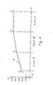
- FIG 4 shows the heating curve H of an aluminum strand 2 in three gas-heated heating zones A, B, C, which are preceded by a preheating zone V.
- the heating curve H in point I shows, the aluminum strand 2 in the preheating zone had already been heated to approximately 250 ° C. before this strand part reached the heating zone A and then to the end of this zone to approximately 370 ° C. (point J) is heated.
- the aluminum strand 2 is then heated up to the end of the heating zone B up to the target temperature of approximately 500 ° C. (point K).
- the temperature of the aluminum strand 2 is then kept at this target temperature (point L) in order to bring about temperature compensation both over the length of a block to be sheared off and radially to the center of the strand.
- thermocouples 12, 13 can be dispensed with in many cases. Then the heating energy of the heating zones B, C for the duration of the forward transport, the shearing process and the return transport of the strand-shaped metal material by the computer 20 and the control device 26 with the aid of the thermocouples 8, 9 and 9, 10, respectively.
Landscapes
- Chemical & Material Sciences (AREA)
- Engineering & Computer Science (AREA)
- Physics & Mathematics (AREA)
- Crystallography & Structural Chemistry (AREA)
- Thermal Sciences (AREA)
- Automation & Control Theory (AREA)
- General Physics & Mathematics (AREA)
- Mechanical Engineering (AREA)
- Materials Engineering (AREA)
- Metallurgy (AREA)
- Organic Chemistry (AREA)
- General Induction Heating (AREA)
- Forging (AREA)
- Control Of Resistance Heating (AREA)
- Length Measuring Devices With Unspecified Measuring Means (AREA)
Priority Applications (1)
| Application Number | Priority Date | Filing Date | Title |
|---|---|---|---|
| AT89104668T ATE79413T1 (de) | 1988-03-24 | 1989-03-16 | Verfahren zum beheizen von strangfoermigem gut. |
Applications Claiming Priority (2)
| Application Number | Priority Date | Filing Date | Title |
|---|---|---|---|
| DE3809932A DE3809932C1 (US06589383-20030708-C00041.png) | 1988-03-24 | 1988-03-24 | |
| DE3809932 | 1988-03-24 |
Publications (2)
| Publication Number | Publication Date |
|---|---|
| EP0334200A1 EP0334200A1 (de) | 1989-09-27 |
| EP0334200B1 true EP0334200B1 (de) | 1992-08-12 |
Family
ID=6350575
Family Applications (1)
| Application Number | Title | Priority Date | Filing Date |
|---|---|---|---|
| EP89104668A Expired - Lifetime EP0334200B1 (de) | 1988-03-24 | 1989-03-16 | Verfahren zum Beheizen von strangförmigem Gut |
Country Status (4)
| Country | Link |
|---|---|
| EP (1) | EP0334200B1 (US06589383-20030708-C00041.png) |
| AT (1) | ATE79413T1 (US06589383-20030708-C00041.png) |
| DE (1) | DE3809932C1 (US06589383-20030708-C00041.png) |
| ES (1) | ES2094114T3 (US06589383-20030708-C00041.png) |
Cited By (1)
| Publication number | Priority date | Publication date | Assignee | Title |
|---|---|---|---|---|
| WO2003076096A1 (en) * | 2002-03-14 | 2003-09-18 | Singapore Institute Of Manufacturing Technology | Heating apparatus for formable metals |
Families Citing this family (2)
| Publication number | Priority date | Publication date | Assignee | Title |
|---|---|---|---|---|
| DE9201878U1 (de) * | 1992-02-14 | 1992-04-09 | Zinser Textilmaschinen Gmbh, 7333 Ebersbach | Heizeinrichtung zur Wärmebehandlung synthetischer Fäden |
| DE10337502B4 (de) * | 2003-08-14 | 2006-03-30 | Kramer, Carl, Prof. Dr.-Ing. | Verfahren zum Betrieb einer Durchlauf-Wärmebehandlungsanlage für Warenbahnen und Bänder mit überwiegend konvektiver Wärmeübertragung |
Family Cites Families (8)
| Publication number | Priority date | Publication date | Assignee | Title |
|---|---|---|---|---|
| CH218873A (de) * | 1939-06-07 | 1942-01-15 | Barmag Barmer Maschf | Verfahren zur Herstellung von zylindrischen Kunstseidenwickeln. |
| US2664283A (en) * | 1947-07-17 | 1953-12-29 | Selas Corp Of America | Furnace control system |
| DE2047499B1 (de) * | 1970-09-26 | 1971-12-16 | W Kleppe & Co Kg | Vorrichtung zum Herstellen von schmied baren Stucken aus Stangen, Knüppeln oder dergleichen |
| GB1570916A (en) * | 1976-02-06 | 1980-07-09 | Nippon Steel Corp | Method of induction heating of metal materials |
| AT351337B (de) * | 1978-03-24 | 1979-07-25 | Franz Kroesbacher Kommanditges | Verfahren zur herstellung von erwaermten spaltstuecken fuer gesenkschmieden |
| DE2907960C3 (de) * | 1979-03-01 | 1984-04-19 | Elhaus, Friedrich Wilhelm, Dipl.-Ing., 5600 Wuppertal | Verfahren und Vorrichtung zum kontinuierlichen Wärmebehandeln von vereinzeltem, langgestrecktem metallischen Gut |
| DE3322874C1 (de) * | 1983-06-24 | 1984-10-11 | Friedrich Wilhelm Dipl.-Ing. 7761 Moos Elhaus | Anlage mit einem Durchlaufofen zum Anwaermen oder Waermebehandeln von Stranggussbarren |
| US4559854A (en) * | 1984-08-06 | 1985-12-24 | Brown, Boveri & Cie Aktiengesellschaft | Cutting apparatus for stock in the form of bars |
-
1988
- 1988-03-24 DE DE3809932A patent/DE3809932C1/de not_active Expired
-
1989
- 1989-03-16 AT AT89104668T patent/ATE79413T1/de not_active IP Right Cessation
- 1989-03-16 EP EP89104668A patent/EP0334200B1/de not_active Expired - Lifetime
- 1989-03-16 ES ES89104668T patent/ES2094114T3/es not_active Expired - Lifetime
Cited By (1)
| Publication number | Priority date | Publication date | Assignee | Title |
|---|---|---|---|---|
| WO2003076096A1 (en) * | 2002-03-14 | 2003-09-18 | Singapore Institute Of Manufacturing Technology | Heating apparatus for formable metals |
Also Published As
| Publication number | Publication date |
|---|---|
| DE3809932C1 (US06589383-20030708-C00041.png) | 1989-06-22 |
| EP0334200A1 (de) | 1989-09-27 |
| ATE79413T1 (de) | 1992-08-15 |
| ES2094114T3 (es) | 1997-01-16 |
Similar Documents
| Publication | Publication Date | Title |
|---|---|---|
| DE3432341C2 (US06589383-20030708-C00041.png) | ||
| DE19540978A1 (de) | Produktionsanlage zum kontinuierlichen- oder diskontinuierlichen Auswalzen von Warmband | |
| EP1444059A1 (de) | Steuerverfahren für eine einer kühlstrecke vorgeordnete fertigstrasse zum walzen von metall-warmband | |
| DE2310116A1 (de) | Kuehlmittelregelung fuer warmbandwalzenstrassen | |
| DE3210676C2 (de) | Verfahen zum Strahlungserwärmen von Vorformlingen | |
| DE3201352C2 (de) | Verfahren zum induktiven Erhitzen von metallischen Werkstücken mit Abschnitten unterschiedlicher Dicke | |
| EP3341142B1 (de) | Verfahren zum betreiben einer anlage nach dem csp-konzept | |
| DE2907960C3 (de) | Verfahren und Vorrichtung zum kontinuierlichen Wärmebehandeln von vereinzeltem, langgestrecktem metallischen Gut | |
| EP0334200B1 (de) | Verfahren zum Beheizen von strangförmigem Gut | |
| EP2767600A1 (de) | Verfahren zur Herstellung insbesondere von Stahl-Langprodukten, sowie eine Einrichtung zur Durchführung des Verfahrens | |
| AT392747B (de) | Verfahren und anordnung zum walzen von draht -oder stabmaterial | |
| DE3340722C2 (de) | Verfahren und Vorrichtung zur Regelung eines Elektroschweißvorganges | |
| EP3877140A1 (de) | Verfahren und vorrichtung für die kontrolle eines dickenprofils einer folienbahn | |
| EP0036968B1 (de) | Verfahren zur Herstellung gelöteter, mehrlagiger Metallrohre und Vorrichtung zur Durchführung des Verfahrens | |
| DE2040148B2 (de) | Verfahren und vorrichtung zum betreiben eines stossofens mit nachgeschalteten breitbandwalzwerk | |
| DE60007006T2 (de) | Steuerungsvorrichtung für einen Trockner in einer Anlage zur Herstellung von Gipsbauplatten | |
| CH642505A5 (en) | Device for the inductive heating of elongated workpieces | |
| DE69224596T2 (de) | Verfahren und Vorrichtung zur automatischen Steuerung von mit Strahlrohren beheizten Durchlauföfen | |
| EP0206235A2 (de) | Verfahren und Vorrichtung zum Anstauchen von Stabstahl | |
| EP0893167B1 (de) | Walzstrasse | |
| DE4126175A1 (de) | Verfahren und vorrichtung zum erwaermen von elektrisch leitfaehigem material | |
| DE102018127347A1 (de) | Verfahren zur optimierten Herstellung von metallischen Stahl- und Eisenlegierungen mit hohen Kohlenstoffgehalten in Warmwalz- und Grobblechwerken | |
| EP3934822B1 (de) | Verfahren zur herstellung eines metallischen bandes oder blechs | |
| DE896694C (de) | Einrichtung zum Haerten von Blechen unter Zugspannung | |
| DE1752297B2 (de) | Einrichtung zum selbsttaetigen aufrechterhalten einer vorgegebenen temperatur in bewegtem walzgut |
Legal Events
| Date | Code | Title | Description |
|---|---|---|---|
| PUAI | Public reference made under article 153(3) epc to a published international application that has entered the european phase |
Free format text: ORIGINAL CODE: 0009012 |
|
| AK | Designated contracting states |
Kind code of ref document: A1 Designated state(s): AT CH ES FR GB IT LI |
|
| 17P | Request for examination filed |
Effective date: 19890909 |
|
| 17Q | First examination report despatched |
Effective date: 19910902 |
|
| GRAA | (expected) grant |
Free format text: ORIGINAL CODE: 0009210 |
|
| AK | Designated contracting states |
Kind code of ref document: B1 Designated state(s): AT CH ES FR GB IT LI |
|
| REF | Corresponds to: |
Ref document number: 79413 Country of ref document: AT Date of ref document: 19920815 Kind code of ref document: T |
|
| ITF | It: translation for a ep patent filed | ||
| REG | Reference to a national code |
Ref country code: ES Ref legal event code: BA2A Ref document number: 2094114 Country of ref document: ES Kind code of ref document: T3 |
|
| ET | Fr: translation filed | ||
| GBT | Gb: translation of ep patent filed (gb section 77(6)(a)/1977) | ||
| PLBE | No opposition filed within time limit |
Free format text: ORIGINAL CODE: 0009261 |
|
| STAA | Information on the status of an ep patent application or granted ep patent |
Free format text: STATUS: NO OPPOSITION FILED WITHIN TIME LIMIT |
|
| 26N | No opposition filed | ||
| REG | Reference to a national code |
Ref country code: ES Ref legal event code: FG2A Ref document number: 2094114 Country of ref document: ES Kind code of ref document: T3 |
|
| REG | Reference to a national code |
Ref country code: GB Ref legal event code: IF02 |
|
| PGFP | Annual fee paid to national office [announced via postgrant information from national office to epo] |
Ref country code: GB Payment date: 20030224 Year of fee payment: 15 |
|
| PGFP | Annual fee paid to national office [announced via postgrant information from national office to epo] |
Ref country code: FR Payment date: 20030318 Year of fee payment: 15 |
|
| PGFP | Annual fee paid to national office [announced via postgrant information from national office to epo] |
Ref country code: AT Payment date: 20030321 Year of fee payment: 15 |
|
| PGFP | Annual fee paid to national office [announced via postgrant information from national office to epo] |
Ref country code: CH Payment date: 20030324 Year of fee payment: 15 |
|
| PGFP | Annual fee paid to national office [announced via postgrant information from national office to epo] |
Ref country code: ES Payment date: 20030325 Year of fee payment: 15 |
|
| PG25 | Lapsed in a contracting state [announced via postgrant information from national office to epo] |
Ref country code: GB Free format text: LAPSE BECAUSE OF NON-PAYMENT OF DUE FEES Effective date: 20040316 Ref country code: AT Free format text: LAPSE BECAUSE OF NON-PAYMENT OF DUE FEES Effective date: 20040316 |
|
| PG25 | Lapsed in a contracting state [announced via postgrant information from national office to epo] |
Ref country code: ES Free format text: LAPSE BECAUSE OF NON-PAYMENT OF DUE FEES Effective date: 20040317 |
|
| PG25 | Lapsed in a contracting state [announced via postgrant information from national office to epo] |
Ref country code: LI Free format text: LAPSE BECAUSE OF NON-PAYMENT OF DUE FEES Effective date: 20040331 Ref country code: CH Free format text: LAPSE BECAUSE OF NON-PAYMENT OF DUE FEES Effective date: 20040331 |
|
| GBPC | Gb: european patent ceased through non-payment of renewal fee |
Effective date: 20040316 |
|
| REG | Reference to a national code |
Ref country code: CH Ref legal event code: PL |
|
| PG25 | Lapsed in a contracting state [announced via postgrant information from national office to epo] |
Ref country code: FR Free format text: LAPSE BECAUSE OF NON-PAYMENT OF DUE FEES Effective date: 20041130 |
|
| REG | Reference to a national code |
Ref country code: FR Ref legal event code: ST |
|
| PG25 | Lapsed in a contracting state [announced via postgrant information from national office to epo] |
Ref country code: IT Free format text: LAPSE BECAUSE OF NON-PAYMENT OF DUE FEES;WARNING: LAPSES OF ITALIAN PATENTS WITH EFFECTIVE DATE BEFORE 2007 MAY HAVE OCCURRED AT ANY TIME BEFORE 2007. THE CORRECT EFFECTIVE DATE MAY BE DIFFERENT FROM THE ONE RECORDED. Effective date: 20050316 |
|
| REG | Reference to a national code |
Ref country code: ES Ref legal event code: FD2A Effective date: 20040317 |