EP0334002B2 - Gewindefräser - Google Patents
Gewindefräser Download PDFInfo
- Publication number
- EP0334002B2 EP0334002B2 EP89101839A EP89101839A EP0334002B2 EP 0334002 B2 EP0334002 B2 EP 0334002B2 EP 89101839 A EP89101839 A EP 89101839A EP 89101839 A EP89101839 A EP 89101839A EP 0334002 B2 EP0334002 B2 EP 0334002B2
- Authority
- EP
- European Patent Office
- Prior art keywords
- thread
- milling cutter
- thread milling
- cutting
- tool
- Prior art date
- Legal status (The legal status is an assumption and is not a legal conclusion. Google has not performed a legal analysis and makes no representation as to the accuracy of the status listed.)
- Expired - Lifetime
Links
- 238000003801 milling Methods 0.000 title claims abstract description 70
- 238000005520 cutting process Methods 0.000 claims abstract description 50
- 238000000034 method Methods 0.000 claims description 14
- 238000005553 drilling Methods 0.000 claims description 13
- 239000000463 material Substances 0.000 claims description 11
- 230000002093 peripheral effect Effects 0.000 claims description 10
- 230000006735 deficit Effects 0.000 abstract description 2
- 230000015572 biosynthetic process Effects 0.000 abstract 1
- 238000004519 manufacturing process Methods 0.000 description 6
- 238000006073 displacement reaction Methods 0.000 description 3
- 230000004323 axial length Effects 0.000 description 2
- 210000001061 forehead Anatomy 0.000 description 2
- 241001295925 Gegenes Species 0.000 description 1
- 229910000997 High-speed steel Inorganic materials 0.000 description 1
- 229910052782 aluminium Inorganic materials 0.000 description 1
- XAGFODPZIPBFFR-UHFFFAOYSA-N aluminium Chemical compound [Al] XAGFODPZIPBFFR-UHFFFAOYSA-N 0.000 description 1
- 230000009286 beneficial effect Effects 0.000 description 1
- 238000007664 blowing Methods 0.000 description 1
- 238000010276 construction Methods 0.000 description 1
- 230000002996 emotional effect Effects 0.000 description 1
- 210000000887 face Anatomy 0.000 description 1
- 238000000227 grinding Methods 0.000 description 1
- 229910052751 metal Inorganic materials 0.000 description 1
- 239000002184 metal Substances 0.000 description 1
- 230000003287 optical effect Effects 0.000 description 1
- 238000010079 rubber tapping Methods 0.000 description 1
- 230000007704 transition Effects 0.000 description 1
Images

Classifications
-
- B—PERFORMING OPERATIONS; TRANSPORTING
- B23—MACHINE TOOLS; METAL-WORKING NOT OTHERWISE PROVIDED FOR
- B23G—THREAD CUTTING; WORKING OF SCREWS, BOLT HEADS, OR NUTS, IN CONJUNCTION THEREWITH
- B23G5/00—Thread-cutting tools; Die-heads
- B23G5/18—Milling cutters
- B23G5/182—Milling cutters combined with other tools
- B23G5/184—Milling cutters combined with other tools combined with drills
-
- Y—GENERAL TAGGING OF NEW TECHNOLOGICAL DEVELOPMENTS; GENERAL TAGGING OF CROSS-SECTIONAL TECHNOLOGIES SPANNING OVER SEVERAL SECTIONS OF THE IPC; TECHNICAL SUBJECTS COVERED BY FORMER USPC CROSS-REFERENCE ART COLLECTIONS [XRACs] AND DIGESTS
- Y10—TECHNICAL SUBJECTS COVERED BY FORMER USPC
- Y10T—TECHNICAL SUBJECTS COVERED BY FORMER US CLASSIFICATION
- Y10T408/00—Cutting by use of rotating axially moving tool
- Y10T408/89—Tool or Tool with support
- Y10T408/904—Tool or Tool with support with pitch-stabilizing ridge
- Y10T408/9048—Extending outwardly from tool-axis
-
- Y—GENERAL TAGGING OF NEW TECHNOLOGICAL DEVELOPMENTS; GENERAL TAGGING OF CROSS-SECTIONAL TECHNOLOGIES SPANNING OVER SEVERAL SECTIONS OF THE IPC; TECHNICAL SUBJECTS COVERED BY FORMER USPC CROSS-REFERENCE ART COLLECTIONS [XRACs] AND DIGESTS
- Y10—TECHNICAL SUBJECTS COVERED BY FORMER USPC
- Y10T—TECHNICAL SUBJECTS COVERED BY FORMER US CLASSIFICATION
- Y10T409/00—Gear cutting, milling, or planing
- Y10T409/30—Milling
- Y10T409/300056—Thread or helix generating
- Y10T409/30056—Thread or helix generating with planetary cutter
Definitions
- the invention relates to a method for introduction a threaded blind hole using a Thread milling cutter according to claim 1 and a thread milling cutter according to claim 2.
- Such a thread milling cutter is by the US-PS 4 651 374 and is designed like a drill, with a drill tip formed by two cutting edges and four spiral flutes on the outer surface of the tool, one of which two start from the peripheral edges of the cutting edges and the others offset axially backwards leak.
- the spiral spirals separated from the flutes Circumferential areas of the tool with relief, provided tooth-like cutting studs, which run approximately in the circumferential direction of the tool.
- the two drill bits at the top of the Tools are around one from the side of the tool inclined to each other, which can be, for example, 120 °; the two Cutting edges are generators of a conical surface.
- the end facing away from the tip of the drill of the known thread milling cutter preferably has one enlarged diameter and is for Set up in a machine tool.
- thread milling cutter it is the purpose of the well-known thread milling cutter, to be as simple and rational as possible Way to make a threaded blind hole.
- the purpose of the thread milling cutter is initially like a drill is rotated about its longitudinal axis and into the one with the threaded blind hole provided material is lowered until the target Hole depth is reached.
- the threaded blind holes produced in this way also have at the bottom of the borehole the usual, over the lowest thread outgoing drill outlet, so that the blind hole is even deeper than the achievable screw-in depth. But sometimes it would be beneficial if extend the threads to the bottom of the borehole would.
- the production of such a threaded blind hole is extremely complex, must be done with specially ground taps be carried out and will therefore, wherever only possible, avoided, so that Thread sack lock in student work, engineering training is considered a design flaw if not special circumstances such a blind hole construction imperative.
- the Invention based on the object, the aforementioned known thread milling cutter in this regard to further develop that he prefers to mill Burr-free blind holes with the greatest possible screw-in depth as well as with a diameter to allow not just the nominal diameter (Outside diameter of the thread milling cutter plus twice the pitch), but can also be arbitrarily larger, so that it is possible is, with one and the same thread milling cutter threaded blind holes to manufacture the same one Slope, but very different diameters have and preferably a burr-free thread inlet exhibit. It will also be a procedure aimed at by which at least one of the mentioned goals is achievable.
- the tool according to the invention not as the well-known, as a drill, but rather designed as a face milling cutter, the face cutting edges form an angle with each other, which is greater than 180 °.
- the invention Tool can thus be reached after reaching the desired drill hole depth immediately to the side any degree, according to which the Tool travels its circular trajectory and raised by the amount of the slope becomes. It is also possible to order the tool to move a relatively small dimension laterally, in the limit, only by the measure of the pitch.
- the face angle of the face milling cutter is according to the invention more than 180 °, so that the tool according to the invention a flat hollow tip has that for self-centering the Tool contributes.
- the bottom of the borehole thus points a flat, conical elevation, but the when relocating the rotating tool abraded immediately by the face milling cutter and thus this lateral displacement not disabled.
- preferred and special essential embodiment of the invention has the lower peripheral edge of the cutter cutting bevel, which is preferred as radially ground edge break at the transition between a face cutter edge and a peripheral edge is trained.
- the invention expressly does not relate only on the stressed thread milling cutter, but also to the claimed milling process a threaded hole whose diameter is larger is the nominal diameter of the thread milling cutter.
- Chip flutes are like with a flute Drill removed from the borehole.
- the end mill cutters involved in the drilling process at least partially with chip breaker grooves provided to prevent that in the cutting area of the tool jammed a chip and to Run the hole leads.
- the thread milling cutter according to the invention can have more than two end cutting edges and preferably three or four end cutting edges, so that the thread milling cutters each extend up to a face milling cutter edge, so that the thread runout or the thread undercut is cut just as cleanly as all other sections of the internal thread produced.
- the replacement is a circular trajectory of 360 ° to complete Making a thread is sufficient. However, this angle is preferred a little run over to a particularly clean thread to reach.
- the axial length of the thread milling cutter is preferably at least equal to the thread depth of the borehole to be produced.
- the tool according to the invention can also used to produce a multi-start thread become.
- the tool according to the invention cannot only for the production of a blind hole, but like the well-known tool for manufacturing a threaded through hole can be used.
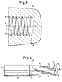
- Drill bits 2 are formed, which are together include an angle ⁇ that is significantly smaller can be as 180 ° and about 120 °.
- Wide flutes 3 separate the cutting edges 2 in Circumferential direction from each other and lead spirally on the shaft not shown in the drawing of the milling cutter upwards to the during the cutting process chips generated during drilling remove.
- the circumferential area of the shaft that between the flutes 3 is undercut Cutting studs 4, which extend in the circumferential direction extend.
- the length of the cutting lugs 4 in the circumferential direction is relatively small.
- the relief grinding of the cutting studs 4 causes that even with the tool rotating do not jam if this per revolution of the Tool raised by the amount of a slope becomes.
- end mill shown in FIG. 2 has instead of the one or two lowest thread lugs a circumferential cutting edge 14, which serves for to provide an undercut 6 (Fig. 3).
- the radially ground chamfer 18 is used for Generation of an edge break in front of the hole Thread milling operation. So that becomes a qualitative high quality burr-free thread guaranteed.
- Fig. 3 is a by a thread mill, such as it is shown in Fig. 2, manufactured threaded blind hole shown, which is formed in a material 5 is and a central axis 8 and an internal thread 7 should have, which in turn on shallow hole end undercut 6 and on opposite thread inlet a broken edge 20 has.
- drilling is as deep as possible this corresponds to the axial length of the edge break 20.
- the thread milling cutter is again along its length Axis 9 is fed against the material 5, the cutting edges 2 remove the material and the chips through the flutes convey outside.
- the tool must have a circular path of at least Cover 360 °; this circular path should but not be much larger, otherwise the Undercut 6 achieved by the peripheral surfaces 14 is long.
- the thread milling cutter can be used as a two, three or Multi-cutter (with four or more cutting edges) trained be, with multi-cutters expedient not all face cutting edges during the drilling process involved; usually only two or three cutting edges are engaged.
- the remaining Cutting edges are set back slightly axially resetting within the perimeter edges 14 must be made so that a qualitative Impairment of the machined thread is excluded.
- 4 is a thread milling cutter with four cutting edges 2 and four flutes 3 shown. In which The tools shown are all four end cutting edges 2 equally wide.
- two of the cutting edges 2, and namely those who are involved in the drilling process Provide recesses 19 which form chip breakers.
- the front teeth 2 are on their peripheral side End with a radially ground chamfer 18 provided that the attachment of an edge break 20 enabled at the beginning of the processing. Moreover is the lifespan of the chamfer 18 Tool increased.
- the tool shown shows how also the circumferential cutting tool shown in FIG. 2 14 to produce the undercut 6 and Cutting studs 4 for milling the internal thread 7, each separated by thread grooves 13 are.
- the tool shank 11 is for clamping of the tool 10 set up in a machine tool and can be a thread, a clamping surface, a slope or other, in the field the usual training for machine tools have to clamp.
- the engagement section 12 faces one the shaft 11 the same or smaller outer diameter on.
- the thread milling cutter can be made of high-speed steel, Hard metal or another suitable Cutting material to be made.
Landscapes
- Engineering & Computer Science (AREA)
- Mechanical Engineering (AREA)
- Milling Processes (AREA)
- Disintegrating Or Milling (AREA)
- Coloring Foods And Improving Nutritive Qualities (AREA)
- Adjustment And Processing Of Grains (AREA)
- Drilling Tools (AREA)
- Sewing Machines And Sewing (AREA)
Description
die Gewindefräserschneiden jeweils bis zu einer Stirnfräserschneide erstrecken, so daß der Gewindeauslauf oder der Gewindefreistich ebenso sauber geschnitten wird wie alle übrigen Abschnitte des hergestellten Innengewindes.
- Fig. 1
- die Spitze des gattungsbildenden Gewindefräsers,
- Fig.2
- die Spitze eines erfindungsgemäßen Gewindefräsers,
- Fig. 3
- den Querschnitt eines mit dem erfindungsgemäßen Gewindefräser hergestellten Gewinde-Sacklochs, und
- Fig. 4
- die Seitenansicht eines erfindungsgemäßen Gewindefräsers.
Claims (6)
- Verfahren zum Einbringen einer Gewinde-Sackbohrung in ein Werkstück mittels eines Gewindefräsers (10) mit einem länglichen Schaft (11), der an seinem Umfang mindestens eine mit Schneidstollen (4) versehene Gewindefräserschneide aufweist und an seinem unteren Ende als Stirnfräser ausgebildet ist, dessen Schneiden (2) zum Schaft (11) hin einen Stirnwinkel (β) einschließen, der größer als 180° ist wobei der Gewindefräser (10)in eine Drehung um die Längsachse (9) des Schaftes (11) versetzt wird,zum Einbringen einer Ausgangsbohrung in Richtung der Längsachse (9) in das Werkstück hinein vorwärtsbewegt wird,nach Erreichen seiner Bohrtiefe unter Beibehaltung seiner Drehung seitlich versetzt wird,unter Beibehaltung seiner Drehung rückwärts bewegt wird, dabei mindestens eine wendelförmige Umlaufbewegung durchführt und hierbei längs der Umfangswand der Ausgangsbohrung mit den Schneidstollen (4) ein Muttergewinde in das Werkstück schneidet, wobei der kleinste Durchmesser des Muttergewindes nicht kleiner ist als der Durchmesser der Ausgangsbohrung, undnach Erreichen seiner größten Bohrtiefe und Beenden seiner Vorwärtsbewegung und vor irgendeiner Rückwärtsbewegung unmittelbar seitlich so lange in das Material (5) des Werkstücks hinein versetzt wird, bis er den Umfang des beliebig großen Muttergewindes erreicht hat.
- Gewindefräser zur Durchführung des Verfahrens nach Anspruch 1, mit einem länglichen Schaft (11), der an seinem Umfang mindestens eine, mit Schneidstollen (4) versehene Gewindefräserschneide aufweist und an seinem unteren Ende als Stirnfräser ausgebildet ist, dessen Schneiden (2) zum Schaft hin zur Bildung einer Hohlspitze am unteren Ende des Gewindefräsers (10) einen Stirnwinkel (β) einschließen, der größer als 180° ist.
- Gewindefräser nach Anspruch 2, dadurch gekennzeichnet, daß die oder jede Gewindefräserschneide am unteren Ende des Gewindefräsers (10) einen Endstollen mit einer länglichen Umfangsschneide (14) aufweist.
- Gewindefräser nach Anspruch 3, dadurch gekennzeichnet, daß am Übergang zwischen Stirnfräserschneide (2) und Umfangsschneide (14) ein radial hinterschliffener Kantenbruch (18) vorgesehen ist.
- Gewindefräser nach einem der Ansprüche 2 bis 4, dadurch gekennzeichnet, daß mindestens zwei Stirnfräserschneiden (2) vorgesehen sind.
- Gewindefräser nach einem der Ansprüche 2 bis 5, dadurch gekennzeichnet, daß bevorzugt bei einem Gewindefräserdurchmesser von mehr als 20 mm mindestens eine der am Bohrvorgang beteiligten Stirnfräserschneiden (2) Spanbrechernuten (19) aufweist.
Applications Claiming Priority (3)
| Application Number | Priority Date | Filing Date | Title |
|---|---|---|---|
| DE888803565U DE8803565U1 (de) | 1988-03-16 | 1988-03-16 | Gewindefraeser |
| DE3808797A DE3808797A1 (de) | 1988-03-16 | 1988-03-16 | Gewindefraeser |
| DE3808797 | 1988-03-16 |
Publications (4)
| Publication Number | Publication Date |
|---|---|
| EP0334002A2 EP0334002A2 (de) | 1989-09-27 |
| EP0334002A3 EP0334002A3 (en) | 1990-10-03 |
| EP0334002B1 EP0334002B1 (de) | 1995-08-30 |
| EP0334002B2 true EP0334002B2 (de) | 2002-09-25 |
Family
ID=39356666
Family Applications (1)
| Application Number | Title | Priority Date | Filing Date |
|---|---|---|---|
| EP89101839A Expired - Lifetime EP0334002B2 (de) | 1988-03-16 | 1989-02-02 | Gewindefräser |
Country Status (5)
| Country | Link |
|---|---|
| US (1) | US4930949A (de) |
| EP (1) | EP0334002B2 (de) |
| AT (1) | ATE127051T1 (de) |
| CA (1) | CA1322264C (de) |
| DE (2) | DE8803565U1 (de) |
Cited By (1)
| Publication number | Priority date | Publication date | Assignee | Title |
|---|---|---|---|---|
| CN103920943A (zh) * | 2013-01-16 | 2014-07-16 | 株洲钻石切削刀具股份有限公司 | 一种螺纹加工铣刀 |
Families Citing this family (20)
| Publication number | Priority date | Publication date | Assignee | Title |
|---|---|---|---|---|
| ATE58662T1 (de) * | 1988-03-30 | 1990-12-15 | Felix Leeb | Vorrichtung und werkzeug zur herstellung aller bekannten gewindearten (ausser saegegewinde) in einem arbeitsgang. |
| DE3939795A1 (de) * | 1989-12-01 | 1991-06-06 | Schmitt M Norbert Dipl Kaufm D | Verfahren zur herstellung einer gewindebohrung |
| US5678962A (en) * | 1994-09-06 | 1997-10-21 | Makino Inc. | Integral boring and threading tool and method |
| US6012882A (en) * | 1995-09-12 | 2000-01-11 | Turchan; Manuel C. | Combined hole making, threading, and chamfering tool with staggered thread cutting teeth |
| DE19548199A1 (de) * | 1995-12-22 | 1997-06-26 | Link Johann & Ernst Gmbh & Co | Verfahren zur Herstellung einer Gewindebohrung sowie Werkzeug zur Durchführung eines solchen Verfahrens |
| US5733078A (en) * | 1996-06-18 | 1998-03-31 | Osg Corporation | Drilling and threading tool |
| DE19739370A1 (de) | 1997-09-09 | 1999-03-11 | Schmitt M Norbert Dipl Kaufm D | Gewindefräsbohr-Werkzeug für Werkstoffe höherer Festigkeit |
| JPH11170114A (ja) * | 1997-12-11 | 1999-06-29 | Honda Motor Co Ltd | ドリル刃付きねじ切りフライス |
| DE19927386A1 (de) * | 1999-06-16 | 2001-01-04 | Fette Wilhelm Gmbh | Verfahren zur Herstellung einer Gewindebohrung und Werkzeug hierfür |
| DE10318203A1 (de) * | 2003-04-22 | 2004-11-11 | Gühring, Jörg, Dr. | Verfahren, Werkzeug und Vorrichtung zur Herstellung von Gewinden |
| DE102005014422B4 (de) * | 2005-03-24 | 2019-10-24 | EMUGE-Werk Richard Glimpel GmbH & Co. KG Fabrik für Präzisionswerkzeuge | Bohrgewindefräser |
| IL167779A (en) * | 2005-03-31 | 2013-09-30 | Hanita Metal Works Ltd | Milling balls |
| US7357606B1 (en) | 2006-02-03 | 2008-04-15 | United States Of America As Represented By The Administrator Of The National Aeronautics And Space Administration | Self-advancing step-tap tool |
| DE102006005887A1 (de) * | 2006-02-09 | 2007-08-16 | Ernst Reime Vertriebs Gmbh | Verfahren zur Herstellung einer Gewindebohrung mit Ansenkung und Bohrer zur Durchführung des Verfahrens |
| US20090074526A1 (en) * | 2007-09-18 | 2009-03-19 | Yg-1 Co., Ltd. | Compound Relief Tap |
| US20100260568A1 (en) * | 2007-10-29 | 2010-10-14 | Osg Corporation | Thread milling cutter |
| JP5756562B2 (ja) * | 2012-03-09 | 2015-07-29 | オーエスジー株式会社 | スパイラルタップ |
| CN104470665A (zh) * | 2012-07-17 | 2015-03-25 | Osg株式会社 | 螺旋丝锥及其制造方法 |
| JP6692932B2 (ja) * | 2017-01-18 | 2020-05-13 | オーエスジー株式会社 | ねじ切りフライス |
| KR200493892Y1 (ko) * | 2019-10-04 | 2021-06-22 | 송태범 | 박판용 스레드밀 |
Citations (1)
| Publication number | Priority date | Publication date | Assignee | Title |
|---|---|---|---|---|
| DE3627798A1 (de) † | 1986-08-16 | 1988-02-18 | Rolf Klenk Gmbh & Co Kg | Verfahren und werkzeug zur herstellung von gewindebohrungen |
Family Cites Families (10)
| Publication number | Priority date | Publication date | Assignee | Title |
|---|---|---|---|---|
| US124570A (en) * | 1872-03-12 | Improvement in combined taps and cutters | ||
| US2557733A (en) * | 1948-04-06 | 1951-06-19 | Walter S Forcier | Self-cutting tap |
| US2684492A (en) * | 1949-10-25 | 1954-07-27 | Gen Electric | Combination drilling and tapping tool |
| GB1500380A (en) * | 1975-05-12 | 1978-02-08 | Hitachi Metals Ltd | Threading tap |
| JPS5524862A (en) * | 1978-08-08 | 1980-02-22 | Yamada Akio | Bit with saw-teethed cutting edge and straight cutting edge |
| US4271554A (en) * | 1979-01-09 | 1981-06-09 | Allen-Stevens Corp. | Combination drill and tap tool |
| JPS624515A (ja) * | 1985-07-01 | 1987-01-10 | Honda Motor Co Ltd | ドリルタツプ |
| DE3786096T2 (de) * | 1986-03-13 | 1993-10-14 | Turchan Manuel C | Methode und Werkzeug zum Gewindeschneidbohren. |
| US4761844A (en) * | 1986-03-17 | 1988-08-09 | Turchan Manuel C | Combined hole making and threading tool |
| US4651374A (en) * | 1986-03-17 | 1987-03-24 | Turchan Manuel C | Combined hole making and threading tool |
-
1988
- 1988-03-16 DE DE888803565U patent/DE8803565U1/de not_active Expired
- 1988-03-16 DE DE3808797A patent/DE3808797A1/de not_active Ceased
-
1989
- 1989-02-02 AT AT89101839T patent/ATE127051T1/de not_active IP Right Cessation
- 1989-02-02 EP EP89101839A patent/EP0334002B2/de not_active Expired - Lifetime
- 1989-02-24 CA CA000592056A patent/CA1322264C/en not_active Expired - Fee Related
- 1989-02-28 US US07/316,818 patent/US4930949A/en not_active Expired - Lifetime
Patent Citations (1)
| Publication number | Priority date | Publication date | Assignee | Title |
|---|---|---|---|---|
| DE3627798A1 (de) † | 1986-08-16 | 1988-02-18 | Rolf Klenk Gmbh & Co Kg | Verfahren und werkzeug zur herstellung von gewindebohrungen |
Cited By (2)
| Publication number | Priority date | Publication date | Assignee | Title |
|---|---|---|---|---|
| CN103920943A (zh) * | 2013-01-16 | 2014-07-16 | 株洲钻石切削刀具股份有限公司 | 一种螺纹加工铣刀 |
| CN103920943B (zh) * | 2013-01-16 | 2016-09-14 | 株洲钻石切削刀具股份有限公司 | 一种螺纹加工铣刀 |
Also Published As
| Publication number | Publication date |
|---|---|
| CA1322264C (en) | 1993-09-21 |
| EP0334002A3 (en) | 1990-10-03 |
| DE8803565U1 (de) | 1988-09-01 |
| EP0334002B1 (de) | 1995-08-30 |
| DE3808797A1 (de) | 1989-10-05 |
| US4930949A (en) | 1990-06-05 |
| ATE127051T1 (de) | 1995-09-15 |
| EP0334002A2 (de) | 1989-09-27 |
Similar Documents
| Publication | Publication Date | Title |
|---|---|---|
| EP0334002B2 (de) | Gewindefräser | |
| EP2830799B1 (de) | Bohrer | |
| DE102004059264B4 (de) | Werkzeug und Verfahren zur Erzeugung eines Gewindes in einem Werkstück | |
| DE102005022503B4 (de) | Werkzeug und Verfahren zur Erzeugung eines Gewindes | |
| DE202022100029U1 (de) | Spiralbohrer mit einer spiralförmigen Stufenbohrspitze | |
| EP2929966B1 (de) | Vollfräswerkzeug zur rotierenden Materialbearbeitung | |
| DE20303656U1 (de) | Stufenbohrer | |
| EP1314506A2 (de) | Gewindeschneidwerkzeug | |
| DE20015550U1 (de) | Stufenbohrer | |
| DE3627798C2 (de) | Verfahren und Kombinationswerkzeug zum Herstellen von Gewindebohrungen | |
| DE3413108A1 (de) | Ringlochschneider | |
| DE3831046A1 (de) | Hohlfraeser zur herstellug von kreisrunden ausnehmungen mit stufenlos veraenderlichem durchmesser | |
| WO1989009108A1 (fr) | Dispositif et outil pour realiser des taraudages sans avant-trous dans un materiau plein | |
| DE3246663A1 (de) | Kombinationswerkzeug zur herstellung einer gewindebohrung | |
| EP3093089A1 (de) | Rotationswerkzeug | |
| DE3629033C2 (de) | ||
| DE29703475U1 (de) | Bohrwerkzeug | |
| DE3044001C2 (de) | ||
| DE202013101404U1 (de) | Bohrwerkzeug | |
| WO2023213816A1 (de) | Stufenbohrer | |
| EP0780182A1 (de) | Verfahren zur Herstellung einer Gewindebohrung sowie Werkzeug zur Durchführung eines solchen Verfahrens | |
| DE19927386A1 (de) | Verfahren zur Herstellung einer Gewindebohrung und Werkzeug hierfür | |
| DE2420204A1 (de) | Hohlbohrwerkzeug zur herstellung von bohrungen, insbesondere langen durchgehenden bohrungen grossen durchmessers | |
| DE102018131237A1 (de) | Stufenbohrer | |
| DE3922707A1 (de) | Verfahren zum herstellen von gewindebohrungen und werkzeug zur ausuebung dieses verfahrens |
Legal Events
| Date | Code | Title | Description |
|---|---|---|---|
| PUAI | Public reference made under article 153(3) epc to a published international application that has entered the european phase |
Free format text: ORIGINAL CODE: 0009012 |
|
| AK | Designated contracting states |
Kind code of ref document: A2 Designated state(s): AT BE CH DE ES FR GB GR IT LI LU NL SE |
|
| PUAL | Search report despatched |
Free format text: ORIGINAL CODE: 0009013 |
|
| AK | Designated contracting states |
Kind code of ref document: A3 Designated state(s): AT BE CH DE ES FR GB GR IT LI LU NL SE |
|
| RHK1 | Main classification (correction) |
Ipc: B23G 1/34 |
|
| 17P | Request for examination filed |
Effective date: 19901105 |
|
| 17Q | First examination report despatched |
Effective date: 19920217 |
|
| GRAA | (expected) grant |
Free format text: ORIGINAL CODE: 0009210 |
|
| AK | Designated contracting states |
Kind code of ref document: B1 Designated state(s): AT BE CH DE ES FR GB GR IT LI LU NL SE |
|
| PG25 | Lapsed in a contracting state [announced via postgrant information from national office to epo] |
Ref country code: BE Effective date: 19950830 Ref country code: GR Free format text: LAPSE BECAUSE OF FAILURE TO SUBMIT A TRANSLATION OF THE DESCRIPTION OR TO PAY THE FEE WITHIN THE PRESCRIBED TIME-LIMIT Effective date: 19950830 Ref country code: ES Free format text: THE PATENT HAS BEEN ANNULLED BY A DECISION OF A NATIONAL AUTHORITY Effective date: 19950830 Ref country code: NL Free format text: LAPSE BECAUSE OF FAILURE TO SUBMIT A TRANSLATION OF THE DESCRIPTION OR TO PAY THE FEE WITHIN THE PRESCRIBED TIME-LIMIT Effective date: 19950830 |
|
| REF | Corresponds to: |
Ref document number: 127051 Country of ref document: AT Date of ref document: 19950915 Kind code of ref document: T |
|
| REF | Corresponds to: |
Ref document number: 58909401 Country of ref document: DE Date of ref document: 19951005 |
|
| ITF | It: translation for a ep patent filed | ||
| PG25 | Lapsed in a contracting state [announced via postgrant information from national office to epo] |
Ref country code: SE Effective date: 19951130 |
|
| GBT | Gb: translation of ep patent filed (gb section 77(6)(a)/1977) |
Effective date: 19951122 |
|
| ET | Fr: translation filed | ||
| NLV1 | Nl: lapsed or annulled due to failure to fulfill the requirements of art. 29p and 29m of the patents act | ||
| PG25 | Lapsed in a contracting state [announced via postgrant information from national office to epo] |
Ref country code: LU Free format text: LAPSE BECAUSE OF NON-PAYMENT OF DUE FEES Effective date: 19960229 |
|
| PLAV | Examination of admissibility of opposition |
Free format text: ORIGINAL CODE: EPIDOS OPEX |
|
| PLBQ | Unpublished change to opponent data |
Free format text: ORIGINAL CODE: EPIDOS OPPO |
|
| PLBI | Opposition filed |
Free format text: ORIGINAL CODE: 0009260 |
|
| PLBQ | Unpublished change to opponent data |
Free format text: ORIGINAL CODE: EPIDOS OPPO |
|
| PLBI | Opposition filed |
Free format text: ORIGINAL CODE: 0009260 |
|
| PLBF | Reply of patent proprietor to notice(s) of opposition |
Free format text: ORIGINAL CODE: EPIDOS OBSO |
|
| 26 | Opposition filed |
Opponent name: JOH. & ERNST LINK GMBH & CO. KG Effective date: 19960523 |
|
| 26 | Opposition filed |
Opponent name: JOH. & ERNST LINK GMBH & CO. KG Effective date: 19960523 Opponent name: TURCHAN, MANUEL Effective date: 19960530 |
|
| PLBF | Reply of patent proprietor to notice(s) of opposition |
Free format text: ORIGINAL CODE: EPIDOS OBSO |
|
| PLBF | Reply of patent proprietor to notice(s) of opposition |
Free format text: ORIGINAL CODE: EPIDOS OBSO |
|
| PLBF | Reply of patent proprietor to notice(s) of opposition |
Free format text: ORIGINAL CODE: EPIDOS OBSO |
|
| PLAW | Interlocutory decision in opposition |
Free format text: ORIGINAL CODE: EPIDOS IDOP |
|
| APAC | Appeal dossier modified |
Free format text: ORIGINAL CODE: EPIDOS NOAPO |
|
| APAE | Appeal reference modified |
Free format text: ORIGINAL CODE: EPIDOS REFNO |
|
| APAC | Appeal dossier modified |
Free format text: ORIGINAL CODE: EPIDOS NOAPO |
|
| REG | Reference to a national code |
Ref country code: GB Ref legal event code: IF02 |
|
| APAC | Appeal dossier modified |
Free format text: ORIGINAL CODE: EPIDOS NOAPO |
|
| PLAW | Interlocutory decision in opposition |
Free format text: ORIGINAL CODE: EPIDOS IDOP |
|
| PUAH | Patent maintained in amended form |
Free format text: ORIGINAL CODE: 0009272 |
|
| STAA | Information on the status of an ep patent application or granted ep patent |
Free format text: STATUS: PATENT MAINTAINED AS AMENDED |
|
| 27A | Patent maintained in amended form |
Effective date: 20020925 |
|
| AK | Designated contracting states |
Kind code of ref document: B2 Designated state(s): AT BE CH DE ES FR GB GR IT LI LU NL SE |
|
| REG | Reference to a national code |
Ref country code: CH Ref legal event code: AEN Free format text: AUFRECHTERHALTUNG DES PATENTES IN GEAENDERTER FORM |
|
| GBTA | Gb: translation of amended ep patent filed (gb section 77(6)(b)/1977) | ||
| ET3 | Fr: translation filed ** decision concerning opposition | ||
| APAH | Appeal reference modified |
Free format text: ORIGINAL CODE: EPIDOSCREFNO |
|
| PGFP | Annual fee paid to national office [announced via postgrant information from national office to epo] |
Ref country code: CH Payment date: 20080129 Year of fee payment: 20 |
|
| PGFP | Annual fee paid to national office [announced via postgrant information from national office to epo] |
Ref country code: IT Payment date: 20080226 Year of fee payment: 20 Ref country code: DE Payment date: 20080131 Year of fee payment: 20 Ref country code: GB Payment date: 20080130 Year of fee payment: 20 |
|
| PGFP | Annual fee paid to national office [announced via postgrant information from national office to epo] |
Ref country code: AT Payment date: 20080213 Year of fee payment: 20 |
|
| PGFP | Annual fee paid to national office [announced via postgrant information from national office to epo] |
Ref country code: FR Payment date: 20080208 Year of fee payment: 20 |
|
| REG | Reference to a national code |
Ref country code: CH Ref legal event code: PL |
|
| REG | Reference to a national code |
Ref country code: GB Ref legal event code: PE20 Expiry date: 20090201 |
|
| PG25 | Lapsed in a contracting state [announced via postgrant information from national office to epo] |
Ref country code: GB Free format text: LAPSE BECAUSE OF EXPIRATION OF PROTECTION Effective date: 20090201 |