EP0334002B2 - Thread milling cutter - Google Patents
Thread milling cutter Download PDFInfo
- Publication number
- EP0334002B2 EP0334002B2 EP89101839A EP89101839A EP0334002B2 EP 0334002 B2 EP0334002 B2 EP 0334002B2 EP 89101839 A EP89101839 A EP 89101839A EP 89101839 A EP89101839 A EP 89101839A EP 0334002 B2 EP0334002 B2 EP 0334002B2
- Authority
- EP
- European Patent Office
- Prior art keywords
- thread
- milling cutter
- thread milling
- cutting
- tool
- Prior art date
- Legal status (The legal status is an assumption and is not a legal conclusion. Google has not performed a legal analysis and makes no representation as to the accuracy of the status listed.)
- Expired - Lifetime
Links
- 238000003801 milling Methods 0.000 title claims abstract description 70
- 238000005520 cutting process Methods 0.000 claims abstract description 50
- 238000000034 method Methods 0.000 claims description 14
- 238000005553 drilling Methods 0.000 claims description 13
- 239000000463 material Substances 0.000 claims description 11
- 230000002093 peripheral effect Effects 0.000 claims description 10
- 230000006735 deficit Effects 0.000 abstract description 2
- 230000015572 biosynthetic process Effects 0.000 abstract 1
- 238000004519 manufacturing process Methods 0.000 description 6
- 238000006073 displacement reaction Methods 0.000 description 3
- 230000004323 axial length Effects 0.000 description 2
- 210000001061 forehead Anatomy 0.000 description 2
- 241001295925 Gegenes Species 0.000 description 1
- 229910000997 High-speed steel Inorganic materials 0.000 description 1
- 229910052782 aluminium Inorganic materials 0.000 description 1
- XAGFODPZIPBFFR-UHFFFAOYSA-N aluminium Chemical compound [Al] XAGFODPZIPBFFR-UHFFFAOYSA-N 0.000 description 1
- 230000009286 beneficial effect Effects 0.000 description 1
- 238000007664 blowing Methods 0.000 description 1
- 238000010276 construction Methods 0.000 description 1
- 230000002996 emotional effect Effects 0.000 description 1
- 210000000887 face Anatomy 0.000 description 1
- 238000000227 grinding Methods 0.000 description 1
- 229910052751 metal Inorganic materials 0.000 description 1
- 239000002184 metal Substances 0.000 description 1
- 230000003287 optical effect Effects 0.000 description 1
- 238000010079 rubber tapping Methods 0.000 description 1
- 230000007704 transition Effects 0.000 description 1
Images

Classifications
-
- B—PERFORMING OPERATIONS; TRANSPORTING
- B23—MACHINE TOOLS; METAL-WORKING NOT OTHERWISE PROVIDED FOR
- B23G—THREAD CUTTING; WORKING OF SCREWS, BOLT HEADS, OR NUTS, IN CONJUNCTION THEREWITH
- B23G5/00—Thread-cutting tools; Die-heads
- B23G5/18—Milling cutters
- B23G5/182—Milling cutters combined with other tools
- B23G5/184—Milling cutters combined with other tools combined with drills
-
- Y—GENERAL TAGGING OF NEW TECHNOLOGICAL DEVELOPMENTS; GENERAL TAGGING OF CROSS-SECTIONAL TECHNOLOGIES SPANNING OVER SEVERAL SECTIONS OF THE IPC; TECHNICAL SUBJECTS COVERED BY FORMER USPC CROSS-REFERENCE ART COLLECTIONS [XRACs] AND DIGESTS
- Y10—TECHNICAL SUBJECTS COVERED BY FORMER USPC
- Y10T—TECHNICAL SUBJECTS COVERED BY FORMER US CLASSIFICATION
- Y10T408/00—Cutting by use of rotating axially moving tool
- Y10T408/89—Tool or Tool with support
- Y10T408/904—Tool or Tool with support with pitch-stabilizing ridge
- Y10T408/9048—Extending outwardly from tool-axis
-
- Y—GENERAL TAGGING OF NEW TECHNOLOGICAL DEVELOPMENTS; GENERAL TAGGING OF CROSS-SECTIONAL TECHNOLOGIES SPANNING OVER SEVERAL SECTIONS OF THE IPC; TECHNICAL SUBJECTS COVERED BY FORMER USPC CROSS-REFERENCE ART COLLECTIONS [XRACs] AND DIGESTS
- Y10—TECHNICAL SUBJECTS COVERED BY FORMER USPC
- Y10T—TECHNICAL SUBJECTS COVERED BY FORMER US CLASSIFICATION
- Y10T409/00—Gear cutting, milling, or planing
- Y10T409/30—Milling
- Y10T409/300056—Thread or helix generating
- Y10T409/30056—Thread or helix generating with planetary cutter
Definitions
- the invention relates to a method for introduction a threaded blind hole using a Thread milling cutter according to claim 1 and a thread milling cutter according to claim 2.
- Such a thread milling cutter is by the US-PS 4 651 374 and is designed like a drill, with a drill tip formed by two cutting edges and four spiral flutes on the outer surface of the tool, one of which two start from the peripheral edges of the cutting edges and the others offset axially backwards leak.
- the spiral spirals separated from the flutes Circumferential areas of the tool with relief, provided tooth-like cutting studs, which run approximately in the circumferential direction of the tool.
- the two drill bits at the top of the Tools are around one from the side of the tool inclined to each other, which can be, for example, 120 °; the two Cutting edges are generators of a conical surface.
- the end facing away from the tip of the drill of the known thread milling cutter preferably has one enlarged diameter and is for Set up in a machine tool.
- thread milling cutter it is the purpose of the well-known thread milling cutter, to be as simple and rational as possible Way to make a threaded blind hole.
- the purpose of the thread milling cutter is initially like a drill is rotated about its longitudinal axis and into the one with the threaded blind hole provided material is lowered until the target Hole depth is reached.
- the threaded blind holes produced in this way also have at the bottom of the borehole the usual, over the lowest thread outgoing drill outlet, so that the blind hole is even deeper than the achievable screw-in depth. But sometimes it would be beneficial if extend the threads to the bottom of the borehole would.
- the production of such a threaded blind hole is extremely complex, must be done with specially ground taps be carried out and will therefore, wherever only possible, avoided, so that Thread sack lock in student work, engineering training is considered a design flaw if not special circumstances such a blind hole construction imperative.
- the Invention based on the object, the aforementioned known thread milling cutter in this regard to further develop that he prefers to mill Burr-free blind holes with the greatest possible screw-in depth as well as with a diameter to allow not just the nominal diameter (Outside diameter of the thread milling cutter plus twice the pitch), but can also be arbitrarily larger, so that it is possible is, with one and the same thread milling cutter threaded blind holes to manufacture the same one Slope, but very different diameters have and preferably a burr-free thread inlet exhibit. It will also be a procedure aimed at by which at least one of the mentioned goals is achievable.
- the tool according to the invention not as the well-known, as a drill, but rather designed as a face milling cutter, the face cutting edges form an angle with each other, which is greater than 180 °.
- the invention Tool can thus be reached after reaching the desired drill hole depth immediately to the side any degree, according to which the Tool travels its circular trajectory and raised by the amount of the slope becomes. It is also possible to order the tool to move a relatively small dimension laterally, in the limit, only by the measure of the pitch.
- the face angle of the face milling cutter is according to the invention more than 180 °, so that the tool according to the invention a flat hollow tip has that for self-centering the Tool contributes.
- the bottom of the borehole thus points a flat, conical elevation, but the when relocating the rotating tool abraded immediately by the face milling cutter and thus this lateral displacement not disabled.
- preferred and special essential embodiment of the invention has the lower peripheral edge of the cutter cutting bevel, which is preferred as radially ground edge break at the transition between a face cutter edge and a peripheral edge is trained.
- the invention expressly does not relate only on the stressed thread milling cutter, but also to the claimed milling process a threaded hole whose diameter is larger is the nominal diameter of the thread milling cutter.
- Chip flutes are like with a flute Drill removed from the borehole.
- the end mill cutters involved in the drilling process at least partially with chip breaker grooves provided to prevent that in the cutting area of the tool jammed a chip and to Run the hole leads.
- the thread milling cutter according to the invention can have more than two end cutting edges and preferably three or four end cutting edges, so that the thread milling cutters each extend up to a face milling cutter edge, so that the thread runout or the thread undercut is cut just as cleanly as all other sections of the internal thread produced.
- the replacement is a circular trajectory of 360 ° to complete Making a thread is sufficient. However, this angle is preferred a little run over to a particularly clean thread to reach.
- the axial length of the thread milling cutter is preferably at least equal to the thread depth of the borehole to be produced.
- the tool according to the invention can also used to produce a multi-start thread become.
- the tool according to the invention cannot only for the production of a blind hole, but like the well-known tool for manufacturing a threaded through hole can be used.
- Drill bits 2 are formed, which are together include an angle ⁇ that is significantly smaller can be as 180 ° and about 120 °.
- Wide flutes 3 separate the cutting edges 2 in Circumferential direction from each other and lead spirally on the shaft not shown in the drawing of the milling cutter upwards to the during the cutting process chips generated during drilling remove.
- the circumferential area of the shaft that between the flutes 3 is undercut Cutting studs 4, which extend in the circumferential direction extend.
- the length of the cutting lugs 4 in the circumferential direction is relatively small.
- the relief grinding of the cutting studs 4 causes that even with the tool rotating do not jam if this per revolution of the Tool raised by the amount of a slope becomes.
- end mill shown in FIG. 2 has instead of the one or two lowest thread lugs a circumferential cutting edge 14, which serves for to provide an undercut 6 (Fig. 3).
- the radially ground chamfer 18 is used for Generation of an edge break in front of the hole Thread milling operation. So that becomes a qualitative high quality burr-free thread guaranteed.
- Fig. 3 is a by a thread mill, such as it is shown in Fig. 2, manufactured threaded blind hole shown, which is formed in a material 5 is and a central axis 8 and an internal thread 7 should have, which in turn on shallow hole end undercut 6 and on opposite thread inlet a broken edge 20 has.
- drilling is as deep as possible this corresponds to the axial length of the edge break 20.
- the thread milling cutter is again along its length Axis 9 is fed against the material 5, the cutting edges 2 remove the material and the chips through the flutes convey outside.
- the tool must have a circular path of at least Cover 360 °; this circular path should but not be much larger, otherwise the Undercut 6 achieved by the peripheral surfaces 14 is long.
- the thread milling cutter can be used as a two, three or Multi-cutter (with four or more cutting edges) trained be, with multi-cutters expedient not all face cutting edges during the drilling process involved; usually only two or three cutting edges are engaged.
- the remaining Cutting edges are set back slightly axially resetting within the perimeter edges 14 must be made so that a qualitative Impairment of the machined thread is excluded.
- 4 is a thread milling cutter with four cutting edges 2 and four flutes 3 shown. In which The tools shown are all four end cutting edges 2 equally wide.
- two of the cutting edges 2, and namely those who are involved in the drilling process Provide recesses 19 which form chip breakers.
- the front teeth 2 are on their peripheral side End with a radially ground chamfer 18 provided that the attachment of an edge break 20 enabled at the beginning of the processing. Moreover is the lifespan of the chamfer 18 Tool increased.
- the tool shown shows how also the circumferential cutting tool shown in FIG. 2 14 to produce the undercut 6 and Cutting studs 4 for milling the internal thread 7, each separated by thread grooves 13 are.
- the tool shank 11 is for clamping of the tool 10 set up in a machine tool and can be a thread, a clamping surface, a slope or other, in the field the usual training for machine tools have to clamp.
- the engagement section 12 faces one the shaft 11 the same or smaller outer diameter on.
- the thread milling cutter can be made of high-speed steel, Hard metal or another suitable Cutting material to be made.
Landscapes
- Engineering & Computer Science (AREA)
- Mechanical Engineering (AREA)
- Milling Processes (AREA)
- Sewing Machines And Sewing (AREA)
- Disintegrating Or Milling (AREA)
- Coloring Foods And Improving Nutritive Qualities (AREA)
- Adjustment And Processing Of Grains (AREA)
- Drilling Tools (AREA)
Abstract
Description
Die Erfindung betrifft ein Verfahren zum Einbringen
einer Gewinde-Sackbohrung mittels einem
Gewindefräser gemäß Anspruch 1 und einen Gewindefräser
gemäß Anspruch 2.The invention relates to a method for introduction
a threaded blind hole using a
Thread milling cutter according to claim 1 and a thread milling cutter
according to
Ein solcher Gewindefräser ist durch die US-PS
4 651 374 bekannt und ist wie ein Bohrer ausgebildet,
mit einer von zwei Schneiden gebildeten Bohrerspitze
und vier spiralig verlaufenden Spannuten
an der Außenfläche des Werkzeugs, von denen
zwei von den Umfangsrändern der Schneiden ausgehen
und die anderen axial nach hinten versetzt
auslaufen. Im Gegensatz zu einem Bohrer sind
jedoch die von den Spannuten getrennten spiraligen
Umfangsbereiche des Werkzeugs mit hinterschliffenen,
zahnartigen Schneidstollen versehen,
die etwa in Umfangsrichtung des Werkzeugs verlaufen.Such a thread milling cutter is by the US-
Die beiden Bohrerschneiden an der Spitze des Werkzeugs sind um einen von der Seite des Werkzeugs her gemessenen Winkel zueinander geneigt, der beispielsweise 120° betragen kann; die beiden Schneidkanten sind Erzeugende einer Kegelfläche.The two drill bits at the top of the Tools are around one from the side of the tool inclined to each other, which can be, for example, 120 °; the two Cutting edges are generators of a conical surface.
Das von der Bohrerspitze abgewandte Ende des bekannten Gewindefräsers weist bevorzugt einen vergrößerten Durchmesser auf und ist zum Einspannen in eine Werkzeugmaschine eingerichtet.The end facing away from the tip of the drill of the known thread milling cutter preferably has one enlarged diameter and is for Set up in a machine tool.
Es ist der Zweck des bekannten Gewindefräsers, auf eine möglichst einfache und rationelle Weise ein Gewinde-Sackloch herzustellen. Zu diesem Zweck wird der Gewindefräser zunächst wie ein Bohrer in Drehung um seine Längsachse versetzt und in das mit dem Gewinde-Sackloch zu versehende Material abgesenkt, bis die angestrebte Bohrlochtiefe erreicht ist.It is the purpose of the well-known thread milling cutter, to be as simple and rational as possible Way to make a threaded blind hole. To this The purpose of the thread milling cutter is initially like a drill is rotated about its longitudinal axis and into the one with the threaded blind hole provided material is lowered until the target Hole depth is reached.
Dann wird das Werkzeug leicht abgehoben, so daß seine Spitze nicht mehr vom kegelig vertieften Bohrlochgrund zentriert ist, und es wird in eine solche Drehung versetzt, daß die Umfangsgeschwindigkeit der erforderlichen Schnittgeschwindigkeit an den Schneidstollen entspricht. Nun wird das Werkzeug unter stets aufrechterhaltener, paralleler Ausrichtung zur Bohrlochachse gegenüber dieser um die Tiefe der zu erzielenden Gewindegänge seitlich versetzt, wonach das Werkzeug mit seiner Mittelachse einer kreisförmigen Bahnkurve folgt, deren Radius der erwähnten seitlichen Versetzung entspricht. Auf diese Weise legt das Werkzeug eine Bahn von mindestens 360° zurück. Gleichzeitig wird das Werkzeug um das Maß der Gewindesteigung gleichmäßig angehoben. Nun ist über die gesamte Bohrlochlänge ein fertiges Sacklochgewinde gefräst. Der Fräser muß jetzt nur wieder auf das Bohrloch zentriert werden und kann dann aus dem Bohrloch herausgezogen werden.Then the tool is lifted off slightly, so that its tip is no longer recessed from the cone Hole center is centered and it will be in a such rotation that the peripheral speed the required cutting speed on the cutting studs. Well now the tool under always maintained, parallel Alignment to the borehole axis opposite this by the depth of the threads to be achieved laterally offset, after which the tool with its central axis is a circular trajectory follows, the radius of which mentioned lateral displacement equivalent. This way the tool attaches a path of at least 360 ° back. At the same time, the tool is around the measure of Thread pitch evenly raised. Now is A finished blind hole thread over the entire length of the borehole milled. The router just has to go again centered on the borehole and can then pulled out of the borehole.
Auf diese Weise ist es mittels einer Spezial-Gewindefräsmaschine bereits gelungen, in Aluminium mit einer einzigen Spindel und somit einem einzigen Gewindefräser pro Minute mehr als 120 Sacklöcher zu bohren und mit einem Innengewinde zu versehen. Der Gewindeeinlauf dieser Sacklöcher weist aber unvermeidlich einen Grat auf, der beim Eindrehen von Gewindebolzen zwischen Außenund Innengewinde geraten kann, das Eindrehen des Gewindebolzens hemmt und zu Schäden am Gewinde führt. Das Entgraten aber ist maschinell meist nicht in befriedigender Weise möglich und geschieht meist von Hand, wodurch der Vorteil des raschen Bohr- und Gewindeschneidevorgangs wieder teilweise zunichte gemacht wird, der durch den bekannten Fräser erreicht wurde.In this way it is using a special thread milling machine already succeeded in aluminum with a single spindle and thus one single thread milling cutter per minute more than 120 Drill blind holes and with an internal thread to provide. The thread inlet of these blind holes but inevitably has a ridge that the Screwing in threaded bolts between the outer and Internal thread can get screwed of the threaded bolt inhibits and damage to the Thread leads. However, deburring is machine mostly not possible in a satisfactory manner and mostly done by hand, which is the advantage of rapid drilling and tapping process again is partially nullified by the known milling cutter was achieved.
Die auf diese Weise hergestellten Gewinde-Sacklöcher haben außerdem am Bohrlochgrund den üblichen, über den untersten Gewindegang hinausreichenden Bohrerauslauf, so daß das Sackloch selbst tiefer ist als die erzielbare Einschraubtiefe. Manchmal wäre es aber vorteilhaft, wenn sich die Gewindegänge bis zum Bohrlochgrund erstrekken würden. Die Herstellung eines solchen Gewinde-Sackloches ist jedoch außerordentlich aufwendig, muß mit speziell geschliffenen Gewindebohrern durchgeführt werden und wird daher, wo immer nur möglich, vermieden, so daß ein solches Gewindesacklock in Studienarbeiten beilngenieursausbildung als Konstruktionsfehler gilt, wenn nicht besondere Umstände eine solche Sacklochkonstruktion zwingend erfordern.The threaded blind holes produced in this way also have at the bottom of the borehole the usual, over the lowest thread outgoing drill outlet, so that the blind hole is even deeper than the achievable screw-in depth. But sometimes it would be beneficial if extend the threads to the bottom of the borehole would. The production of such a threaded blind hole is extremely complex, must be done with specially ground taps be carried out and will therefore, wherever only possible, avoided, so that Thread sack lock in student work, engineering training is considered a design flaw if not special circumstances such a blind hole construction imperative.
An eine Serienfertigung solcher Sacklöcker und gar mit der oben beschriebenen Fertigungsgeschwindigkeit ist nicht zu denken.A series production of such bag-holes and even with the manufacturing speed described above is unthinkable.
Ein weiterer Nachteil der bekannten Gewindefräser liegt darin, daß man praktisch für jeden Gewinde-Nenndurchmesser ein eigenes Werkzeug benötigt. Dies erfordert aber gerade bei Feingewindebohrungen mit verhältnismäßig großem Durchmesser die Bereitstellung einer großen Anzahl teuerer Gewindefräser.Another disadvantage of the known thread milling cutter lies in the fact that one is practically for everyone Thread nominal diameter a separate tool needed. However, this requires especially with fine-thread bores with a relatively large diameter the provision of a large number expensive thread milling cutter.
Ausgehend von dieser Problemlage liegt der Erfindung die Aufgabe zugrunde, den eingangs genannten, bekannten Gewindefräser dahingehend weiterzubilden, daß er zum Fräsen von bevorzugt gratfreien Sacklöchern mit größtmöglicher Einschraubtiefe sowie mit einem Durchmesser zu ermöglichen, der nicht nur dem Nenndurchmesser (Außendurchmesser des Gewindefräsers zuzüglich der zweifachen Ganghöhe) entspricht, sondern auch beliebig größer sein kann, so daß es möglich ist, mit ein und demselben Gewindefräser Gewinde-Sacklöcher herzustellen, die zwar die gleiche Steigung, aber stark unterschiedliche Durchmesser aufweisen sowie bevorzugt einen gratfreien Gewindeeinlauf aufweisen. Es wird auch ein Verfahren angestrebt, durch welches mindestens eines der genannten Ziele erreichbar ist.Based on this problem, the Invention based on the object, the aforementioned known thread milling cutter in this regard to further develop that he prefers to mill Burr-free blind holes with the greatest possible screw-in depth as well as with a diameter to allow not just the nominal diameter (Outside diameter of the thread milling cutter plus twice the pitch), but can also be arbitrarily larger, so that it is possible is, with one and the same thread milling cutter threaded blind holes to manufacture the same one Slope, but very different diameters have and preferably a burr-free thread inlet exhibit. It will also be a procedure aimed at by which at least one of the mentioned goals is achievable.
Diese Aufgabe wird durch die Merkmale der
Ansprüche 1 und 2 gelöst.This task is characterized by the characteristics of
Hierbei ist das erfindungsgemäße Werkzeug nicht, wie das bekannte, als Bohrer, sondern vielmehr als Stirnfräser ausgebildet, wobei die Stirnschneiden miteinander einen Winkel einschließen, der größer als 180° ist beträgt. Das erfindungsgemäße Werkzeug kann somit nach Erreichen der gewünschten Bohrlochtiefe unmittelbar seitlich um ein beliebiges Maß versetzt werden, wonach das Werkzeug seine kreisförmige Bahnkurve zurücklegt und hierbei um das Maß der Steigung angehoben wird. Es ist auch möglich, das Werkzeug um ein verhältnismäßig geringes Maß seitlich zu versetzen, im Grenzfall nur um das Maß der Ganghöhe.Here is the tool according to the invention not as the well-known, as a drill, but rather designed as a face milling cutter, the face cutting edges form an angle with each other, which is greater than 180 °. The invention Tool can thus be reached after reaching the desired drill hole depth immediately to the side any degree, according to which the Tool travels its circular trajectory and raised by the amount of the slope becomes. It is also possible to order the tool to move a relatively small dimension laterally, in the limit, only by the measure of the pitch.
Beim Fräsen wird der in einem einzigen Umlauf erzielbare Gewindedurchmesser lediglich dadurch beschränkt, daß die seitliche Versetzung von Gewindfräserachse und Bohrlochachse nicht mehr als höchstens den Außendurchmesser des Gewindefräsers betragen darf, da sonst kein Bohrloch, sondern eine Kreisnut gefräst wird. Grundsätzlich ist es aber möglich, durch mehrere Werkzeugumläufe letztlich ein Gewinde-Sackloch mit praktisch unbegrenztem Durchmesser zu fräsen. Dies ist besonders für die optische und feinmechanische Industrie wichtig, in der präzise Fein-Innengewinde mit verhältnismäßig großem Durchmesser hergestellt werden müssen.When milling, this is done in a single pass achievable thread diameter only because of this limited that the lateral displacement of Thread mill axis and borehole axis no longer than at most the outside diameter of the thread milling cutter may be, otherwise there is no borehole, but a circular groove is milled. in principle it is possible, however, through several tool revolutions ultimately a threaded blind hole with practical mill unlimited diameter. This is special for the optical and precision engineering industry important in the precise fine internal thread manufactured with a relatively large diameter Need to become.
Der Stirnwinkel der Stirnfräserschneiden beträgt gemäß der Erfindung mehr als 180°, so daß das erfindungsgemäße Werkzeug eine flache Hohlspitze aufweist, die zur Selbstzentrierung des Werkzeuges beiträgt. Der Bohrlochgrund weist somit eine flache, kegelige Erhebung auf, die aber beim seitlichen Versetzen des rotierenden Werkzeugs durch die Stirnfräserschneiden sofort abgetragen wird und somit diese seitliche Versetzung nicht behindert.The face angle of the face milling cutter is according to the invention more than 180 °, so that the tool according to the invention a flat hollow tip has that for self-centering the Tool contributes. The bottom of the borehole thus points a flat, conical elevation, but the when relocating the rotating tool abraded immediately by the face milling cutter and thus this lateral displacement not disabled.
Es ist grundsätzlich möglich, mit dem erfindungsgemäßen Werkzeug ein Gewinde zu fräsen, dessen Gang sich bis zum flachen Bohrlochgrund erstreckt. Da sich am Bohrlochgrund aber selbst nach dem Ausblasen mit Preßluft Schmutz ansammeln kann, ist es gemäß einer bevorzugten Ausgestaltung der Erfindung von Vorteil, an dem der Werkzeugspitze zugewandten Ende der Gewindefräserschneiden anstelle eines zahnartigen Schneidstollens eine längliche Umfangsschneide vorzusehen, deren Länge bevorzugt das ein- bis zweifache der Gewindesteigung beträgt. Durch diese Umfangsschneiden wird am Bohrlochgrund eine einen Freistich bildende Umfangsnut gebildet, in die der hergestellte Gewindegang ausläuft. Somit ist es möglich, eine Schraube bis auf den Bohrungsgrund einzudrehen.It is basically possible with the invention Tool to mill a thread, whose passage extends to the flat bottom of the borehole extends. Because at the bottom of the borehole itself After blowing out, collect dirt with compressed air can, it is according to a preferred embodiment the invention of advantage on which the End of the thread milling cutter facing the tool tip instead of a tooth-like Cutting cleats an elongated circumferential cutting edge to provide, the length of which preferably the one to is twice the thread pitch. Through this Circumferential cutting becomes one at the bottom of the borehole a circumferential groove forming an undercut, in which the manufactured thread ends. Consequently it is possible to screw one screw down to the bottom of the hole screwed in.
Gemäß einer weiteren, bevorzugten und besonders wesentlichen Ausgestaltung der Erfindung weist die untere Umfangskante des Fräsers eine schneidende Abschrägung auf, die bevorzugt als radial hinterschliffener Kantenbruch am übergang zwischen einer Stirnfräserschneide und einer Umfangsschneide ausgebildet ist.According to another, preferred and special essential embodiment of the invention has the lower peripheral edge of the cutter cutting bevel, which is preferred as radially ground edge break at the transition between a face cutter edge and a peripheral edge is trained.
Mittels dieser Ausbildung ist es möglich, in jene Werkstückoberfläche, in welche ein Gewinde-Sackloch eingebracht werden soll, zunächst eine angesenkte Vertiefung einzufräsen, deren Durchmesser so auf das herzustellende Innengewinde abgestimmt ist, daß dieses in die Ansenkung einläuft. Hierbei wird der Fräser außermittig eingestellt und durchläuft eine Kreisbahn. Nachfolgend wird auf die oben beschriebene Weise das Sackloch gebohrt und das Gewinde gefräst. Wie sich gezeigt hat, wird so das Auftreten eines Grates am Gewindeeinlauf verhindert.With this training it is possible to the workpiece surface in which a threaded blind hole should be introduced, first one countersinked recess, its diameter so on the internal thread to be produced is agreed that this runs into the countersink. Here, the milling cutter is set off-center and runs through a circular path. Below is the blind hole in the manner described above drilled and the thread milled. As shown has a burr on the thread inlet prevented.
Es ist grundsätzlich auch möglich, mit dem weitergebildeten erfindungsgemäßen Fräser das hergestellte Gewindeloch nachträglich am Einlauf anzusenken, doch wird bei diesem Verfahren ein kleiner Grat stets unvermeidbar sein.In principle, it is also possible to use the further developed milling cutter according to the invention manufactured threaded hole at the inlet lower, but with this procedure one small ridges are always inevitable.
Die Erfindung bezieht sich ausdrücklich nicht nur auf den beanspruchten Gewindefräser, sondern auch auf das beanspruchte Verfahren zum Fräsen einer Gewindebohrung, deren Durchmesser grösser ist als der Nenndurchmesser des Gewindefräsers.The invention expressly does not relate only on the stressed thread milling cutter, but also to the claimed milling process a threaded hole whose diameter is larger is the nominal diameter of the thread milling cutter.
Die von den Stirnfräserschneiden gelösten Späne werden durch Spannuten wie bei einem Bohrer aus dem Bohrloch abgeführt. Gemäß einer bevorzugten Ausgestaltung der Erfindung sind aber die am Bohrvorgang beteiligten Stirnfräserschneiden mindestens teilweise mit Spanbrechernuten versehen, um zu verhindern, daß sich im Schnittbereich des Werkzeugs ein Span verklemmt und zum Verlaufen der Bohrung führt.The loosened from the face milling cutter Chip flutes are like with a flute Drill removed from the borehole. According to one are preferred embodiment of the invention the end mill cutters involved in the drilling process at least partially with chip breaker grooves provided to prevent that in the cutting area of the tool jammed a chip and to Run the hole leads.
Der in der Zeichnung der US-PS 4 651 374 gezeigte Gewindefräser weist ferner mehr Spannuten und somit Gewindefräserschneiden als stirnseitige Bohrerschneiden auf. Aus diesem Grund müssen die nicht in einer Bohrerschneide auslaufenden Gewindefräserschneiden gegenüber der Werkzeugspitze zurückversetzt sein, wobei nur jene Gewindefräserschneiden den unteren Gewindeauslauf schneiden können, die in Bohrerschneiden einmünden. Hierdurch wird der Gekindeauslauf unsauber.The one in the drawing of U.S. Patent 4,651,374 The thread milling cutter shown also has more flutes and thus thread milling cutter as the front Drill cutting on. For this reason that do not end in a cutting edge Thread milling cutter opposite the tool tip be set back using only those thread milling cutters the lower thread runout can cut, which open into drill bits. This makes the child's runout unclean.
Der erfindungsgemäße Gewindefräser dagegen
kann gemäß einer weiteren, bevorzugten Ausgestaltung
mehr als zwei Stirnschneiden und vorzugsweise
drei oder vier Stirnschneiden aufweisen, so
daß sich
die Gewindefräserschneiden jeweils bis zu einer
Stirnfräserschneide erstrecken, so daß der Gewindeauslauf
oder der Gewindefreistich ebenso sauber
geschnitten wird wie alle übrigen Abschnitte des
hergestellten Innengewindes.In contrast, according to a further preferred embodiment, the thread milling cutter according to the invention can have more than two end cutting edges and preferably three or four end cutting edges, so that
the thread milling cutters each extend up to a face milling cutter edge, so that the thread runout or the thread undercut is cut just as cleanly as all other sections of the internal thread produced.
Wie oben beschrieben, ist das Zurücklegen einer kreisförmigen Bahnkurve von 360 ° zum vollständigen Herstellens eines Gewindes ausreichend. Bevorzugt wird man diesen Winkel jedoch ein wenig überfahren, um eine besonders saubere Gewindeausführung zu erreichen.As described above, the replacement is a circular trajectory of 360 ° to complete Making a thread is sufficient. However, this angle is preferred a little run over to a particularly clean thread to reach.
Die axiale Länge der Gewindefräserschneiden ist bevorzugt mindestens gleich der Gewindetiefe des herzustellenden Bohrlochs.The axial length of the thread milling cutter is preferably at least equal to the thread depth of the borehole to be produced.
Das erfindungsgemäße Werkzeug kann auch zur Herstellung eines mehrgängigen Gewindes verwendet werden.The tool according to the invention can also used to produce a multi-start thread become.
Das erfindungsgemäße Werkzeug kann nicht nur zur Herstellung einer Sackbohrung, sondern wie das bekannte Werkzeug auch zum Herstellen einer Gewinde-Durchgangsbohrung verwendet werden.The tool according to the invention cannot only for the production of a blind hole, but like the well-known tool for manufacturing a threaded through hole can be used.
Der Gegenstand der Erfindung wird anhand der beigefügten, schematischen Zeichnung beispielsweise noch näher erläutert; in dieser zeigt:
- Fig. 1
- die Spitze des gattungsbildenden Gewindefräsers,
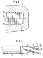
- Fig.2
- die Spitze eines erfindungsgemäßen Gewindefräsers,
- Fig. 3
- den Querschnitt eines mit dem erfindungsgemäßen Gewindefräser hergestellten Gewinde-Sacklochs, und
- Fig. 4
- die Seitenansicht eines erfindungsgemäßen Gewindefräsers.
- Fig. 1
- the tip of the generic thread milling cutter,
- Fig.2
- the tip of a thread milling cutter according to the invention,
- Fig. 3
- the cross section of a threaded blind hole produced with the thread milling cutter according to the invention, and
- Fig. 4
- the side view of a thread milling cutter according to the invention.
In Fig. 1 ist ein bekannter Gewindefräser 1
dargestellt, mit einer Bohrerspitze, die von zwei
Bohrerschneiden 2 gebildet sind, die miteinander
einen Winkel β einschließen, der deutlich kleiner ist
als 180° und etwa 120° betragen kann.1 is a known thread milling cutter 1
shown with a drill tip made by two
Breite Spannuten 3 trennen die Schneiden 2 in
Umfangsrichtung voneinander und führen spiralig
an dem in der Zeichnung nicht dargestellten Schaft
des Fräsers nach oben, um die beim Schnittvorgang
während des Bohrens anfallenden Späne zu
entfernen.
Der Umfangsbereich des Schaftes, der zwischen
den Spannuten 3 liegt, weist hinterschnittene
Schneidstollen 4 auf, die sich in Umfangsrichtung
erstrecken. Die Länge der Schneidstollen 4 in Umfangsrichtung
ist verhältnismäßig gering.The circumferential area of the shaft that between
the
Der Hinterschliff der Schneidstollen 4 bewirkt,
daß diese bei rotierendem Werkzeug selbst dann
nicht klemmen, wenn dieses pro Umdrehung des
Werkzeugs um das Maß einer Steigung angehoben
wird.The relief grinding of the cutting
Bei der in Fig. 2 gezeigten Ausführungsform
der Erfindung weist der gezeigte Gewindefräser 10
eine flache Hohlspitze auf, wobei der zwischen den
Stirnfräserschneiden 2 gebildete Winkel β ein wenig
größer ist als 180°.In the embodiment shown in Fig. 2
According to the invention, the
Ferner weist der in Fig. 2 gezeigte Stirnfräser
anstelle der ein bis zwei untersten Gewindestollen
eine Umfangsschneide 14 auf, die dazu dient, für
einen Freistich 6 (Fig. 3) zu sorgen.Furthermore, the end mill shown in FIG. 2 has
instead of the one or two lowest thread lugs
a
Die radial hinterschliffene Fase 18 dient zur
Erzeugung eines Kantenbruches vor dem Bohrund
Gewindefräsvorgang. Damit wird ein qualitativ
hochwertiges gratfreies Gewinde garantiert.The
In Fig. 3 ist ein durch einen Gewindefräser, wie
er in Fig. 2 gezeigt ist, hergestelltes Gewinde-Sackloch
gezeigt, das in einem Material 5 ausgebildet
ist und eine Mittelachse 8 sowie ein Innengewinde
7 aufweisen soll, welches seinerseits am
flachen Bohrlochende einen Freistich 6 und am
entgegengesetzten Gewindeeinlauf einen Kantenbruch
20 aufweist.In Fig. 3 is a by a thread mill, such as
it is shown in Fig. 2, manufactured threaded blind hole
shown, which is formed in a material 5
is and a
Das in Fig. 3 gezeigte Gewinde-Sackloch wird
durch ein Werkzeug der Fig. 2 auf die folgende
Weise hergestellt:
Zunächst wird maximal so tief gebohrt, wie
dies der axialen Länge des Kantenbruches 20 entspricht.First of all, drilling is as deep as possible
this corresponds to the axial length of the
Nun wird das Werkzeug mit seiner Achse 9
radial soweit versetzt, daß der gewünschte Durchmesser
des Kantenbruches 20 entsteht. Eine Kreisbewegung
um 360° reicht aus, um den Kantenbruch
20 zu erzeugen.Now the tool with its axis 9
radially offset so far that the desired diameter
the
Danach wird das Werkzeug wieder auf die
Bohrlochachse 8 gefahren.Then the tool is put back on the
Nun beginnt der eigentliche Bohrvorgang.Now the actual drilling process begins.
Dem Gewindefräser wird erneut längs seiner
Achse 9 gegen das Material 5 ein Vorschub verliehen,
wobei die Stirnschneiden 2 das Material abtragen
und die Späne durch die Spannuten nach
außen befördern.The thread milling cutter is again along its length
Axis 9 is fed against the material 5,
the
Bei Erreichen der vorgesehenen Bohrtiefe ist
der Bohrlochgrund bei Verwendung des Werkzeugs
der Fig. 2 mit einer leichten kegeligen Erhebung
versehen.When the intended drilling depth is reached
the bottom of the borehole when using the
Nun wird die Drehung des Werkzeugs beibehalten
oder so verändert, daß die optimale Schnittgeschwindigkeit
der Schneidstollen 4 erreicht wird.Now the rotation of the tool is kept
or changed so that the optimal cutting speed
the
Dann wird das Werkzeug mit seiner Achse 9
senkrecht zur Bohrlochachse 8 gegenüber dieser
um ein solches Maß versetzt, daß das Zweifache
dieses Maßes zuzüglich dem Werkzeug-Außendurchmesser
etwa dem Gewinde-Nenndurchmesser
entspricht. Hierbei arbeiten sich die Schneidstollen
4 und die Umfangsschneiden 14 in das
Material 5 hinein.Then the tool with its axis 9
perpendicular to the
Ist der gewünschte Abstand zwischen der
Bohrlochachse 8 und der Werkzeugachse 9 erreicht,
dann wird die Werkzeugachse 9 auf einer
kreisförmigen Bahnkurve über mindestens 360°
bewegt; gleichzeitig wird das Werkzeug 10 um das
Maß der Steigung angehoben. Hierbei wird das
Innengewinde 7 mit dem gewünschten Durchmesser
gefräst.Is the desired distance between the
Das Werkzeug muß eine Kreisbahn von mindestens
360° zurücklegen; diese Kreisbahn sollte
jedoch nicht wesentlich größer sein, da sonst der
von den Umfangsflächen 14 erzielte Freistich 6 zu
lang ist.The tool must have a circular path of at least
Cover 360 °; this circular path should
but not be much larger, otherwise the
Undercut 6 achieved by the
Der Gewindefräser kann als Zwei-, Drei- oder Mehrschneider (mit vier oder mehr Schneiden) ausgebildet sein, wobei bei Mehrschneidern zweckmäßigerweise nicht alle Stirnschneiden am Bohrvorgang beteiligt sind; in der Regel sollen nur zwei oder drei Schneiden in Eingriff stehen. Die übrigen Schneiden sind axial leicht zurückgesetzt, wobei das Zurücksetzen innerhalb der Umfangsschneiden 14 vorgenommen werden muß, so daß eine qualitative Beeinträchtigung des bearbeiteten Gewindes ausgeschlossen ist.The thread milling cutter can be used as a two, three or Multi-cutter (with four or more cutting edges) trained be, with multi-cutters expedient not all face cutting edges during the drilling process involved; usually only two or three cutting edges are engaged. The remaining Cutting edges are set back slightly axially resetting within the perimeter edges 14 must be made so that a qualitative Impairment of the machined thread is excluded.
In Fig. 4 ist ein Gewindefräser mit vier Schneiden
2 und vier Spannuten 3 gezeigt. Bei dem
gezeigten Werkzeug sind alle vier Stirnschneiden 2
gleich breit.4 is a thread milling cutter with four
Es ist jedoch auch möglich, nur zwei der Stirnschneiden
2 so auszubilden, daß sie beim Bohrvorgang
schneiden, und die beiden anderen Stirnschneiden
axial ein wenig zurückzuversetzen. In
diesem Fall ist es zweckmäßig, jene Spannuten 3,
die den jeweils beim Bohrvorgang schneidenden
Stirnschneiden 2 zugeordnet sind, breiter auszubilden
als die anderen Spannuten 3, die lediglich die
beim Gewindefräsvorgang anfallenden Späne abzuführen
haben.However, it is also possible to use only two of the
Ferner sind zwei der Stirnschneiden 2, und
zwar jene, die am Bohrvorgang beteiligt sind, mit
Aussparungen 19 versehen, die Spanbrecher bilden.Furthermore, two of the
Die Stirnzähne 2 sind an ihrem umfangsseitigen
Ende mit einer radial hinterschliffenen Fase 18
versehen, die das Anbringen eines Kantenbruches
20 zu Beginn der Bearbeitung ermöglicht. Außerdem
wird durch die Fase 18 die Lebensdauer des
Werkzeugs erhöht.The
Im übrigen weist das gezeigte Werkzeug wie
auch das in Fig. 2 gezeigte Werkzeug Umfangsschneiden
14 zum Erzeugen des Freistiches 6 sowie
Schneidstollen 4 zum Fräsen des Innengewindes
7 auf, die jeweils von Gewinderillen 13 getrennt
sind.Otherwise, the tool shown shows how
also the circumferential cutting tool shown in FIG. 2
14 to produce the undercut 6 and
Der Werkzeugschaft 11 ist zum Einspannen
des Werkzeugs 10 in eine Werkzeugmaschine eingerichtet
und kann ein Gewinde, eine Spannfläche,
eine Spannschräge oder sonstige, auf dem Gebiet
der Werkzeugmaschinen übliche Ausbildungen
zum Einspannen aufweisen.The
Der Eingriffsabschnitt 12 weist einen gegenüber
dem Schaft 11 gleichen oder kleineren Außendurchmesser
auf.The
Der Gewindefräser kann aus Schnellarbeitsstahl, Hartmetall oder einem anderen, geeigneten Schneidstoff hergestellt sein.The thread milling cutter can be made of high-speed steel, Hard metal or another suitable Cutting material to be made.
Claims (6)
- Process for inserting a threaded drill-hole in a workpiece by means of a thread milling cutter (10) with a long shaft (11), which possesses at least one thread cutting blade provided with cutting flutes (4) on its periphery and which at its lower end is designed as a face milling cutter, the blades (2) of which enclose a transverse angle (β) to the shaft (11) of greater than 180°, in which the thread milling cutter (10)is rotated around the longitudinal axis (9) of the shaft (11),is moved forwards into the workpiece in the direction of the longitudinal axis (9) in order to insert an initial drill hole,after reaching its drilling depth is moved sideways whilst maintaining its rotation,is moved backwards while still maintaining its rotation, and in the process carries out at least one spiral revolution thereby cutting a female thread in the workpiece around the peripheral wall of the initial drill hole with the cutting flutes (4), whereby the smallest diameter of the female thread is not smaller than the diameter of the initial drill hole, andafter reaching its greatest drilling depth and completing its forward movement and before any backward movement is moved immediately sideways into the material (5) of the workpiece, until it has reached the desired circumference of the female thread.
- Thread milling cutter for carrying out the process according to Claim 1, with a long shaft (11), which on its periphery possesses at least one thread cutting blade provided with cutting flutes (4) and which at its lower end is designed as a face milling cutter, the blades (2) of which enclose a transverse angle (β) to the shaft greater than 180°, thereby forming a hollow tip at the lower end of the thread milling cutter (10).
- Thread milling cutter according to Claim 2, characterized in that the one or more thread cutting blades possesses an end flute with a longitudinal peripheral blade (14) at the lower end of the thread milling cutter (10).
- Thread milling cutter according to Claim 3, characterized in that a radially relief-ground chamfer (18) is provided at the junction between the face milling blade (2) and the peripheral blade (14).
- Thread milling cutter according to one of Claims 2 to 4, characterized in that at least two face milling blades (2) are provided
- Thread milling cutter according to one of Claims 2 to 5, characterized in that for a thread milling cutter diameter of more than 20 mm, preferably at least one of the face milling blades (2) involved in the drilling process possesses chip breaking grooves (19).
Applications Claiming Priority (3)
| Application Number | Priority Date | Filing Date | Title |
|---|---|---|---|
| DE3808797 | 1988-03-16 | ||
| DE888803565U DE8803565U1 (en) | 1988-03-16 | 1988-03-16 | THREAD MILLING |
| DE3808797A DE3808797A1 (en) | 1988-03-16 | 1988-03-16 | THREAD MILLING |
Publications (4)
| Publication Number | Publication Date |
|---|---|
| EP0334002A2 EP0334002A2 (en) | 1989-09-27 |
| EP0334002A3 EP0334002A3 (en) | 1990-10-03 |
| EP0334002B1 EP0334002B1 (en) | 1995-08-30 |
| EP0334002B2 true EP0334002B2 (en) | 2002-09-25 |
Family
ID=39356666
Family Applications (1)
| Application Number | Title | Priority Date | Filing Date |
|---|---|---|---|
| EP89101839A Expired - Lifetime EP0334002B2 (en) | 1988-03-16 | 1989-02-02 | Thread milling cutter |
Country Status (5)
| Country | Link |
|---|---|
| US (1) | US4930949A (en) |
| EP (1) | EP0334002B2 (en) |
| AT (1) | ATE127051T1 (en) |
| CA (1) | CA1322264C (en) |
| DE (2) | DE3808797A1 (en) |
Cited By (1)
| Publication number | Priority date | Publication date | Assignee | Title |
|---|---|---|---|---|
| CN103920943A (en) * | 2013-01-16 | 2014-07-16 | 株洲钻石切削刀具股份有限公司 | Thread machining milling cutter |
Families Citing this family (20)
| Publication number | Priority date | Publication date | Assignee | Title |
|---|---|---|---|---|
| ATE58662T1 (en) * | 1988-03-30 | 1990-12-15 | Felix Leeb | DEVICE AND TOOL FOR MANUFACTURING ALL KNOWN TYPES OF THREAD (EXCEPT SAW THREADS) IN ONE OPERATION. |
| DE3939795A1 (en) * | 1989-12-01 | 1991-06-06 | Schmitt M Norbert Dipl Kaufm D | METHOD FOR PRODUCING A THREADED HOLE |
| US5678962A (en) * | 1994-09-06 | 1997-10-21 | Makino Inc. | Integral boring and threading tool and method |
| US6012882A (en) * | 1995-09-12 | 2000-01-11 | Turchan; Manuel C. | Combined hole making, threading, and chamfering tool with staggered thread cutting teeth |
| DE19548199A1 (en) * | 1995-12-22 | 1997-06-26 | Link Johann & Ernst Gmbh & Co | Process for producing a threaded bore and tool for carrying out such a process |
| US5733078A (en) * | 1996-06-18 | 1998-03-31 | Osg Corporation | Drilling and threading tool |
| DE19739370A1 (en) | 1997-09-09 | 1999-03-11 | Schmitt M Norbert Dipl Kaufm D | Thread cutting drilling tool for high strength material |
| JPH11170114A (en) * | 1997-12-11 | 1999-06-29 | Honda Motor Co Ltd | Thread milling cutter with drill blade |
| DE19927386A1 (en) * | 1999-06-16 | 2001-01-04 | Fette Wilhelm Gmbh | Threaded boring producing process, involving making core boring using boring milling head of diameter greater than that of shaft region with milling thread cutter |
| DE10318203A1 (en) * | 2003-04-22 | 2004-11-11 | Gühring, Jörg, Dr. | Method, tool and device for producing threads |
| DE102005014422B4 (en) * | 2005-03-24 | 2019-10-24 | EMUGE-Werk Richard Glimpel GmbH & Co. KG Fabrik für Präzisionswerkzeuge | Drill |
| IL167779A (en) * | 2005-03-31 | 2013-09-30 | Hanita Metal Works Ltd | Orbital end mill |
| US7357606B1 (en) | 2006-02-03 | 2008-04-15 | United States Of America As Represented By The Administrator Of The National Aeronautics And Space Administration | Self-advancing step-tap tool |
| DE102006005887A1 (en) * | 2006-02-09 | 2007-08-16 | Ernst Reime Vertriebs Gmbh | Method for producing a countersunk bore and drill bit for carrying out the method |
| US20090074526A1 (en) * | 2007-09-18 | 2009-03-19 | Yg-1 Co., Ltd. | Compound Relief Tap |
| DE112007003696B4 (en) * | 2007-10-29 | 2024-02-01 | Osg Corp. | Thread milling cutter |
| JP5756562B2 (en) * | 2012-03-09 | 2015-07-29 | オーエスジー株式会社 | Spiral tap |
| WO2014013549A1 (en) * | 2012-07-17 | 2014-01-23 | オーエスジー株式会社 | Spiral tap and manufacturing method therefor |
| CN109963678B (en) * | 2017-01-18 | 2021-10-22 | Osg株式会社 | thread milling cutter |
| KR200493892Y1 (en) * | 2019-10-04 | 2021-06-22 | 송태범 | Thread mill for the sheet |
Citations (1)
| Publication number | Priority date | Publication date | Assignee | Title |
|---|---|---|---|---|
| DE3627798A1 (en) † | 1986-08-16 | 1988-02-18 | Rolf Klenk Gmbh & Co Kg | Method and tool for making tapped holes |
Family Cites Families (10)
| Publication number | Priority date | Publication date | Assignee | Title |
|---|---|---|---|---|
| US124570A (en) * | 1872-03-12 | Improvement in combined taps and cutters | ||
| US2557733A (en) * | 1948-04-06 | 1951-06-19 | Walter S Forcier | Self-cutting tap |
| US2684492A (en) * | 1949-10-25 | 1954-07-27 | Gen Electric | Combination drilling and tapping tool |
| GB1500380A (en) * | 1975-05-12 | 1978-02-08 | Hitachi Metals Ltd | Threading tap |
| JPS5524862A (en) * | 1978-08-08 | 1980-02-22 | Yamada Akio | Bit with saw-teethed cutting edge and straight cutting edge |
| US4271554A (en) * | 1979-01-09 | 1981-06-09 | Allen-Stevens Corp. | Combination drill and tap tool |
| JPS624515A (en) * | 1985-07-01 | 1987-01-10 | Honda Motor Co Ltd | drill tap |
| EP0237035B1 (en) * | 1986-03-13 | 1993-06-09 | Turchan, Manuel C. | Method of and tool for thread mill drilling |
| US4761844A (en) * | 1986-03-17 | 1988-08-09 | Turchan Manuel C | Combined hole making and threading tool |
| US4651374A (en) * | 1986-03-17 | 1987-03-24 | Turchan Manuel C | Combined hole making and threading tool |
-
1988
- 1988-03-16 DE DE3808797A patent/DE3808797A1/en not_active Ceased
- 1988-03-16 DE DE888803565U patent/DE8803565U1/en not_active Expired
-
1989
- 1989-02-02 EP EP89101839A patent/EP0334002B2/en not_active Expired - Lifetime
- 1989-02-02 AT AT89101839T patent/ATE127051T1/en not_active IP Right Cessation
- 1989-02-24 CA CA000592056A patent/CA1322264C/en not_active Expired - Fee Related
- 1989-02-28 US US07/316,818 patent/US4930949A/en not_active Expired - Lifetime
Patent Citations (1)
| Publication number | Priority date | Publication date | Assignee | Title |
|---|---|---|---|---|
| DE3627798A1 (en) † | 1986-08-16 | 1988-02-18 | Rolf Klenk Gmbh & Co Kg | Method and tool for making tapped holes |
Cited By (2)
| Publication number | Priority date | Publication date | Assignee | Title |
|---|---|---|---|---|
| CN103920943A (en) * | 2013-01-16 | 2014-07-16 | 株洲钻石切削刀具股份有限公司 | Thread machining milling cutter |
| CN103920943B (en) * | 2013-01-16 | 2016-09-14 | 株洲钻石切削刀具股份有限公司 | A kind of screw thread process milling cutter |
Also Published As
| Publication number | Publication date |
|---|---|
| US4930949A (en) | 1990-06-05 |
| EP0334002A2 (en) | 1989-09-27 |
| DE3808797A1 (en) | 1989-10-05 |
| CA1322264C (en) | 1993-09-21 |
| DE8803565U1 (en) | 1988-09-01 |
| EP0334002B1 (en) | 1995-08-30 |
| EP0334002A3 (en) | 1990-10-03 |
| ATE127051T1 (en) | 1995-09-15 |
Similar Documents
| Publication | Publication Date | Title |
|---|---|---|
| EP0334002B2 (en) | Thread milling cutter | |
| EP2830799B1 (en) | Drill bit | |
| DE102004059264B4 (en) | Tool and method for creating a thread in a workpiece | |
| DE102005022503B4 (en) | Tool and method for producing a thread | |
| DE202022100029U1 (en) | Twist drills with a spiral stepped drill bit | |
| EP2929966B1 (en) | Solid milling tool for machining of materials | |
| DE20303656U1 (en) | Conical drill bit adjacent step-graduated sections linked by conical transition zones | |
| EP1314506A2 (en) | Thread cutting tool | |
| DE20015550U1 (en) | Step drill | |
| DE3627798C2 (en) | Method and combination tool for making tapped holes | |
| DE3413108A1 (en) | RING HOLE CUTTER | |
| DE3831046A1 (en) | CAVES FOR THE PRODUCTION OF CIRCULAR ROUND EXCLUSIONS WITH CONTINUOUSLY VARIABLE DIAMETERS | |
| WO1989009108A1 (en) | Device and tool for producing internal screw threads without pilot drilling in a solid material | |
| DE3246663A1 (en) | Combination tool for producing a tapped hole | |
| EP3093089A1 (en) | Rotary tool | |
| DE3629033C2 (en) | ||
| DE29703475U1 (en) | Drilling tool | |
| DE3044001C2 (en) | ||
| DE202013101404U1 (en) | drilling | |
| WO2023213816A1 (en) | Step drill | |
| EP0780182A1 (en) | Method to form an internal thread and tool therefor | |
| DE19927386A1 (en) | Threaded boring producing process, involving making core boring using boring milling head of diameter greater than that of shaft region with milling thread cutter | |
| DE2420204A1 (en) | Large diameter hollow boring tool - leaves inner core during cutting process | |
| DE102018131237A1 (en) | Step drill | |
| DE3922707A1 (en) | Method of producing tapped holes and tool for carrying out this method |
Legal Events
| Date | Code | Title | Description |
|---|---|---|---|
| PUAI | Public reference made under article 153(3) epc to a published international application that has entered the european phase |
Free format text: ORIGINAL CODE: 0009012 |
|
| AK | Designated contracting states |
Kind code of ref document: A2 Designated state(s): AT BE CH DE ES FR GB GR IT LI LU NL SE |
|
| PUAL | Search report despatched |
Free format text: ORIGINAL CODE: 0009013 |
|
| AK | Designated contracting states |
Kind code of ref document: A3 Designated state(s): AT BE CH DE ES FR GB GR IT LI LU NL SE |
|
| RHK1 | Main classification (correction) |
Ipc: B23G 1/34 |
|
| 17P | Request for examination filed |
Effective date: 19901105 |
|
| 17Q | First examination report despatched |
Effective date: 19920217 |
|
| GRAA | (expected) grant |
Free format text: ORIGINAL CODE: 0009210 |
|
| AK | Designated contracting states |
Kind code of ref document: B1 Designated state(s): AT BE CH DE ES FR GB GR IT LI LU NL SE |
|
| PG25 | Lapsed in a contracting state [announced via postgrant information from national office to epo] |
Ref country code: BE Effective date: 19950830 Ref country code: GR Free format text: LAPSE BECAUSE OF FAILURE TO SUBMIT A TRANSLATION OF THE DESCRIPTION OR TO PAY THE FEE WITHIN THE PRESCRIBED TIME-LIMIT Effective date: 19950830 Ref country code: ES Free format text: THE PATENT HAS BEEN ANNULLED BY A DECISION OF A NATIONAL AUTHORITY Effective date: 19950830 Ref country code: NL Free format text: LAPSE BECAUSE OF FAILURE TO SUBMIT A TRANSLATION OF THE DESCRIPTION OR TO PAY THE FEE WITHIN THE PRESCRIBED TIME-LIMIT Effective date: 19950830 |
|
| REF | Corresponds to: |
Ref document number: 127051 Country of ref document: AT Date of ref document: 19950915 Kind code of ref document: T |
|
| REF | Corresponds to: |
Ref document number: 58909401 Country of ref document: DE Date of ref document: 19951005 |
|
| ITF | It: translation for a ep patent filed | ||
| PG25 | Lapsed in a contracting state [announced via postgrant information from national office to epo] |
Ref country code: SE Effective date: 19951130 |
|
| GBT | Gb: translation of ep patent filed (gb section 77(6)(a)/1977) |
Effective date: 19951122 |
|
| ET | Fr: translation filed | ||
| NLV1 | Nl: lapsed or annulled due to failure to fulfill the requirements of art. 29p and 29m of the patents act | ||
| PG25 | Lapsed in a contracting state [announced via postgrant information from national office to epo] |
Ref country code: LU Free format text: LAPSE BECAUSE OF NON-PAYMENT OF DUE FEES Effective date: 19960229 |
|
| PLAV | Examination of admissibility of opposition |
Free format text: ORIGINAL CODE: EPIDOS OPEX |
|
| PLBQ | Unpublished change to opponent data |
Free format text: ORIGINAL CODE: EPIDOS OPPO |
|
| PLBI | Opposition filed |
Free format text: ORIGINAL CODE: 0009260 |
|
| PLBQ | Unpublished change to opponent data |
Free format text: ORIGINAL CODE: EPIDOS OPPO |
|
| PLBI | Opposition filed |
Free format text: ORIGINAL CODE: 0009260 |
|
| PLBF | Reply of patent proprietor to notice(s) of opposition |
Free format text: ORIGINAL CODE: EPIDOS OBSO |
|
| 26 | Opposition filed |
Opponent name: JOH. & ERNST LINK GMBH & CO. KG Effective date: 19960523 |
|
| 26 | Opposition filed |
Opponent name: JOH. & ERNST LINK GMBH & CO. KG Effective date: 19960523 Opponent name: TURCHAN, MANUEL Effective date: 19960530 |
|
| PLBF | Reply of patent proprietor to notice(s) of opposition |
Free format text: ORIGINAL CODE: EPIDOS OBSO |
|
| PLBF | Reply of patent proprietor to notice(s) of opposition |
Free format text: ORIGINAL CODE: EPIDOS OBSO |
|
| PLBF | Reply of patent proprietor to notice(s) of opposition |
Free format text: ORIGINAL CODE: EPIDOS OBSO |
|
| PLAW | Interlocutory decision in opposition |
Free format text: ORIGINAL CODE: EPIDOS IDOP |
|
| APAC | Appeal dossier modified |
Free format text: ORIGINAL CODE: EPIDOS NOAPO |
|
| APAE | Appeal reference modified |
Free format text: ORIGINAL CODE: EPIDOS REFNO |
|
| APAC | Appeal dossier modified |
Free format text: ORIGINAL CODE: EPIDOS NOAPO |
|
| REG | Reference to a national code |
Ref country code: GB Ref legal event code: IF02 |
|
| APAC | Appeal dossier modified |
Free format text: ORIGINAL CODE: EPIDOS NOAPO |
|
| PLAW | Interlocutory decision in opposition |
Free format text: ORIGINAL CODE: EPIDOS IDOP |
|
| PUAH | Patent maintained in amended form |
Free format text: ORIGINAL CODE: 0009272 |
|
| STAA | Information on the status of an ep patent application or granted ep patent |
Free format text: STATUS: PATENT MAINTAINED AS AMENDED |
|
| 27A | Patent maintained in amended form |
Effective date: 20020925 |
|
| AK | Designated contracting states |
Kind code of ref document: B2 Designated state(s): AT BE CH DE ES FR GB GR IT LI LU NL SE |
|
| REG | Reference to a national code |
Ref country code: CH Ref legal event code: AEN Free format text: AUFRECHTERHALTUNG DES PATENTES IN GEAENDERTER FORM |
|
| GBTA | Gb: translation of amended ep patent filed (gb section 77(6)(b)/1977) | ||
| ET3 | Fr: translation filed ** decision concerning opposition | ||
| APAH | Appeal reference modified |
Free format text: ORIGINAL CODE: EPIDOSCREFNO |
|
| PGFP | Annual fee paid to national office [announced via postgrant information from national office to epo] |
Ref country code: CH Payment date: 20080129 Year of fee payment: 20 |
|
| PGFP | Annual fee paid to national office [announced via postgrant information from national office to epo] |
Ref country code: IT Payment date: 20080226 Year of fee payment: 20 Ref country code: DE Payment date: 20080131 Year of fee payment: 20 Ref country code: GB Payment date: 20080130 Year of fee payment: 20 |
|
| PGFP | Annual fee paid to national office [announced via postgrant information from national office to epo] |
Ref country code: AT Payment date: 20080213 Year of fee payment: 20 |
|
| PGFP | Annual fee paid to national office [announced via postgrant information from national office to epo] |
Ref country code: FR Payment date: 20080208 Year of fee payment: 20 |
|
| REG | Reference to a national code |
Ref country code: CH Ref legal event code: PL |
|
| REG | Reference to a national code |
Ref country code: GB Ref legal event code: PE20 Expiry date: 20090201 |
|
| PG25 | Lapsed in a contracting state [announced via postgrant information from national office to epo] |
Ref country code: GB Free format text: LAPSE BECAUSE OF EXPIRATION OF PROTECTION Effective date: 20090201 |