EP0333771B1 - Personenalarmanlage - Google Patents
Personenalarmanlage Download PDFInfo
- Publication number
- EP0333771B1 EP0333771B1 EP88900842A EP88900842A EP0333771B1 EP 0333771 B1 EP0333771 B1 EP 0333771B1 EP 88900842 A EP88900842 A EP 88900842A EP 88900842 A EP88900842 A EP 88900842A EP 0333771 B1 EP0333771 B1 EP 0333771B1
- Authority
- EP
- European Patent Office
- Prior art keywords
- alarm
- infra
- infra red
- red
- transmitter
- Prior art date
- Legal status (The legal status is an assumption and is not a legal conclusion. Google has not performed a legal analysis and makes no representation as to the accuracy of the status listed.)
- Expired - Lifetime
Links
- 230000001960 triggered effect Effects 0.000 claims description 3
- 238000001514 detection method Methods 0.000 claims description 2
- 230000005855 radiation Effects 0.000 claims description 2
- 230000005540 biological transmission Effects 0.000 claims 1
- 230000000694 effects Effects 0.000 claims 1
- 238000012544 monitoring process Methods 0.000 abstract description 7
- 238000012360 testing method Methods 0.000 description 12
- 238000010586 diagram Methods 0.000 description 9
- 238000009434 installation Methods 0.000 description 7
- 230000007257 malfunction Effects 0.000 description 2
- 208000032365 Electromagnetic interference Diseases 0.000 description 1
- 230000004913 activation Effects 0.000 description 1
- 230000003466 anti-cipated effect Effects 0.000 description 1
- 238000004891 communication Methods 0.000 description 1
- 239000013078 crystal Substances 0.000 description 1
- 238000013461 design Methods 0.000 description 1
- 238000009429 electrical wiring Methods 0.000 description 1
- 238000000034 method Methods 0.000 description 1
- 230000010355 oscillation Effects 0.000 description 1
- 230000001360 synchronised effect Effects 0.000 description 1
Images


Classifications
-
- G—PHYSICS
- G08—SIGNALLING
- G08B—SIGNALLING OR CALLING SYSTEMS; ORDER TELEGRAPHS; ALARM SYSTEMS
- G08B1/00—Systems for signalling characterised solely by the form of transmission of the signal
- G08B1/08—Systems for signalling characterised solely by the form of transmission of the signal using electric transmission ; transformation of alarm signals to electrical signals from a different medium, e.g. transmission of an electric alarm signal upon detection of an audible alarm signal
-
- G—PHYSICS
- G08—SIGNALLING
- G08B—SIGNALLING OR CALLING SYSTEMS; ORDER TELEGRAPHS; ALARM SYSTEMS
- G08B21/00—Alarms responsive to a single specified undesired or abnormal condition and not otherwise provided for
- G08B21/02—Alarms for ensuring the safety of persons
- G08B21/0297—Robbery alarms, e.g. hold-up alarms, bag snatching alarms
-
- G—PHYSICS
- G08—SIGNALLING
- G08B—SIGNALLING OR CALLING SYSTEMS; ORDER TELEGRAPHS; ALARM SYSTEMS
- G08B25/00—Alarm systems in which the location of the alarm condition is signalled to a central station, e.g. fire or police telegraphic systems
- G08B25/009—Signalling of the alarm condition to a substation whose identity is signalled to a central station, e.g. relaying alarm signals in order to extend communication range
-
- G—PHYSICS
- G08—SIGNALLING
- G08B—SIGNALLING OR CALLING SYSTEMS; ORDER TELEGRAPHS; ALARM SYSTEMS
- G08B29/00—Checking or monitoring of signalling or alarm systems; Prevention or correction of operating errors, e.g. preventing unauthorised operation
- G08B29/12—Checking intermittently signalling or alarm systems
- G08B29/14—Checking intermittently signalling or alarm systems checking the detection circuits
Definitions
- This invention relates to a personal alarm system which comprises a portable transmitter unit to be worn about the person, or hand carried, and which is operable in an emergency to transmit an alarm signal which is to be received and processed by a central receiving station so that appropriate action can be initiated in response thereto.
- ultrasonic personal alarm transmitter units which issue ultrasonic signals to be received by a dedicated ultrasonic receiver at each location which is to be monitored (which then re-transmits to the central station), but ultrasonic units rely upon crystal devices, which are not robust, and in fact are rather fragile, so that this can cause problems with regard to reliability.
- ultrasonic transmitters it is a feature of existing ultrasonic transmitters that they cannot readily be tested as to their current state of serviceability while in use, and there is therefore a risk that emergency signals may fail to be issued and/or received.
- radio transmitter units are not suitable for use in situations in which the users may be located in any one of a number of different locations when the emergency call has been made.
- a personal alarm system is described in German patent application no DEA3210002.
- the system comprises an infra red receiver positioned in for example a ward in a hospital which receives infra red signals which are transmitted from portable infra red transmitters carried by for example nurses or doctors.
- the present invention has been developed primarily in connection with a personal alarm system which is able to indicate the location at which an emergency call has been made, and using means which are more reliable than ultrasonic transmitter/receiver units of existing systems.
- the personal alarm system may be used to particular advantage in hospitals, especially hospital casualty departments, and in institutions for mentally disturbed or handicapped patients, where attacks on medical staff are quite frequent, and in which it is important for the member of staff to be able easily to issue an emergency call which will be picked-up by a suitable receiver at each of any desired monitoring locations, and for the call to be re-transmitted to the central station in a form which will indicate immediately the location from which the call has been made, so that immediate help can be directed to any person under attack.
- the personal alarm system is used in conjunction with a signal receiving system which comprises one or more of said infra-red receivers, each to be located at a respective one of a plurality of desired monitoring locations, and master receiving equipment to be located at a central or control receiving station to receive warning signals re-transmitted from any one of the infra-red receivers.
- a signal receiving system which comprises one or more of said infra-red receivers, each to be located at a respective one of a plurality of desired monitoring locations, and master receiving equipment to be located at a central or control receiving station to receive warning signals re-transmitted from any one of the infra-red receivers.
- the infra-red receivers are each wired to a central alarm panel which is able to identify the location of an active transmitter.
- each transmitter unit By arranging for each transmitter unit to issue pulsed infra-red signals, it is possible to design the transmitter unit and the corresponding infra-red receiver unit so that a predetermined pulse pattern can be readily detected and then recognised, and this will overcome, or at least minimise the risk of any spurious infra-red signals from triggering an alarm signal to the central control station.
- a test facility is provided which, by incorporating a low-power transmitter circuit within each receiver unit, enables a complete test of the installation to be activated from the central alarm panel.
- all wiring associated with the installation is monitored continuously, creating an alarm condition if a wiring fault or break is detected.
- a portable infra-red transmitter unit is designated generally by reference 10 and forms part of a personal alarm system, the unit 10 being designed so as to be capable of being worn about the person, or hand carried, according to preference of the user.
- the transmitter unit 10 is electrically operable, having a battery compartment, so that in an emergency it can transmit an alarm signal which is received initially by any one of a plurality of dedicated receivers arranged at a number of monitoring locations likely to be visited by the user, and then retransmitted to a central receiving station so that appropriate action can be initiated in response thereto.
- any incoming warning signal will be monitored in such a way as to determine the location from which the emergency call has been made by the user with his own personal portable transmitter unit.
- the transmitter unit 10 is designed as a compact, lightweight and impact-resistant unit, having a housing 11 designed to hang freely from a belt or key-ring, by means of a spring-retained pin 12.
- the transmitter unit 10 is activated by withdrawing the housing 11 from the retaining pin 12, and by this action it is ensured that the infra-red beam which is emitted, as shown by beam profile 13 in Figure 1, is unimpeded by any articles of clothing.
- the housing 11 incorporates a battery compartment 14 in which a standard miniature 12 volt battery (VR22) is housed in an anti-vibration manner.
- the forward end of the housing 11 is provided with an LED array of infra-red emitters and an infra-red window, shown schematically by reference 15.
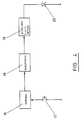
- the electronic components mounted within the housing 11 are shown in the block circuit diagram of Figure 4.
- the electronic components include an astable multivibrator circuit 16 triggered into operation by an activation switch 17, a monostable multivibrator circuit 18, an infra-red LED driver 19 and an infra-red LED array 20.
- the astable and monostable multivibrator circuits 16 and 18 are arranged to produce a continuous train of five microsecond pulses at 4.67 millisecond intervals.
- the pulse train is then fed to driver 19, which is a MOSFET driver, and then to the LED array 20, which comprises a series-parallel combination of high-power infra-red emitters. Therefore, upon emergency operation of the transmitter units 10, a pulsed infra-red output of predetermined pattern can be transmitted, and which can be recognised and received by any one of the infra-red receiver units arranged at the various monitoring locations as required.
- the infra-red receiver comprises a photo diode 21 forming an input to the receiver, for receiving pulsed infra-red signals from any one of the infra-red transmitter units, an infra-red detector and AMP 22, a hit detector 23, a hit counter 24, a comparator 25, a window counter 26, a window generator 27, a window reset 28, a master reset 29, a window synch 30, a time out error 31, an alarm latch 32, a monitoring oscillator 33, an alarm 34, and a test pulse generator 35.
- the window generator 27 comprises an oscillator and multi-stage counter, the generated output being an initial delay of 4.6 milliseconds, followed by a window pulse of 148 microseconds. Transmitter pulses fall within successive windows, each window being triggered by the previously received pulse, via the window reset 28. This synchronisation technique effectively discriminates against any other sources of infra-red radiation which could give rise to spurious signals.
- the window counter 26 is incremented whenever a window is generated.
- the hit detector 23 passes pulses which arrive within a time window through to the pulse hit counter 24.
- the alarm latch 32 is set when the hit counter reaches a pre-set number, and the alarm signal from alarm 34 remains active until manually reset from the central alarm panel at the control station.
- the count comparator 25 notifies the master reset circuit 29 of any discrepancy between the window and hit counters i.e. when no infra-red pulse is received during a time window.
- the master reset circuit 29 causes a reset of the hit counter 24 and the window counter 26 and initiates the start of the next time window, via the window reset 28.
- the window synchronisation circuit synchronises the generation of time windows to an incoming pulse train, and this circuit is active immediately following a window comparator pulse i.e. following a "miss" in any time window.
- the time-out error circuit 31 ensures that a system master reset pulse will be generated, even in the event of a temporary receiver malfunction. Such malfunctions, although rare, may be caused by electro-magnetic interference or electrical noise in the installation.
- FIG. 6 shows three modes of operation, illustrated in the timing diagrams of Figure 6.
- the diagrams illustrate the pulse characteristics, via lines 1 to 7, in which line 1 is the window generator, line 2 is the infra-red detector, line 3 is the comparator, line 4 is the master reset, line 5 is the window reset, line 6 is the window synch, and line 7 is the alarm latch.
- the three possible modes of operation which are normally possible are as follows:
- the hit detector latch is enabled as each generated window opens.
- a pulse from an active transmitter sets the latch and fires a monostable.
- the monostable pulse thereby formed then increments the hit counter, causing a window generator reset and disables the hit detactor latch.
- the window delay period therefore, incoming infra-red pulses are rejected.
- the next window opens, incrementing the window counter and re-enabling the hit detector latch.
- the anticipated transmitter pulse now sets the latch and refires the monostable, which again increments the hit counter and initiates another timing cycle. With successive transmitter pulses, the hit and window counters increment in steps.
- the alarm latch is set when the hit counter has accumulated a preset number of counts.
- a window opens and closes without receiving an input pulse, a discrepancy occurs between the hit and window counters.
- the comparator which is sampled at the end of each window cycle, becomes active and generates a master reset pulse. This resets the hit and window counters and also resets the window generator. In the absence of infra-red signals, the circuit will continue to produce empty timing windows and master reset pulses.
- an input latch in the window synchronisation circuit is enabled by the active comparator. If an infra-red pulse arrives during the window delay period, this latch is set and a master reset is generated. Hence, if the pulse is the first of a train of transmitter pulses, the window generator will be correctly synchronised to the transmitter frequency.
- the system incorporates test facilities, to enable continuous reassurance of safe operation of the system is available.
- each receiver has a test circuitry arranged to generate a low power infra-red pulse train at an identical frequency to that of one of the transmitter units.
- the circuit can be activated from the central alarm panel, so that all receivers in the installation are tested simultaneously. By simulating an active transmitter, the facility provides a complete test of each receiver unit.
- a test unit based on a modified receiver circuit, is used to test the output power and pulse repetition frequency of each transmitter unit, before issue to personnel.
- the infra-red receiver units receive and recognise pulsed infra-red input signals, derived from operation on emergency call of any one of the infra-red transmitter units, and then re-transmits the emergency call via direct electrical wiring to a central control panel at the control or master station.
- each receiver unit transmits an oscillating electrical signal, which is inhibited by the alarm latch, via the alarm signal cable to the central control panel. If the oscillations cease, the central control panel signals an alarm/fault condition.
- This system provides a continuous monitoring of the integrity if both the power and the signal cabling of the installation.
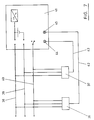
- FIG. 7 of the drawings shows the installation requirements for connection of the infra-red receivers via direct wiring to the central control panel.
- two receiver units only are shown, comprising receiver 36 and receiver 37, and these are connected to low voltage supply and return cables 38 and 39, the installation operating under 13.5 volts supply.
- a test/reset cable daisy chain 40 also extends to all of the receiver units.
- a single cable from each receiver carries an alarm/monitor signal to the central alarm panel 41, and as shown cable 42 connects receiver 36 to an input indication point 43 on the control panel, at which an alarm or fault indication can be given, depending upon whether the test facility is being operated, or a genuine alarm call has been made from a transmitter unit having its infra-red output accessible to the input of any one of the receiver unit(s) at receiver 36.
- cable 43 connects receiver 37 to an alarm/fault indication point 44 on the control panel.
- the system specification of a preferred embodiment is as follows: 1. Transmitter Pulse repetition frequency 214 Hz Pulse width 5 ⁇ s Peak wavelength emission 950 nm Size - length 75 mm - diameter 26 mm Weight (including battery) 60 g Battery type VR-22 or equivalent Battery life (continuous) 45 minutes approx Infra-red beam profile 80% power in ⁇ 16° 2. Receiver Range (line of sight) 20 metres minimum Power consumption (including indicator led) 100 mA approx at 12V
Landscapes
- Physics & Mathematics (AREA)
- General Physics & Mathematics (AREA)
- Business, Economics & Management (AREA)
- Emergency Management (AREA)
- Engineering & Computer Science (AREA)
- Computer Security & Cryptography (AREA)
- Alarm Systems (AREA)
Claims (4)
- Personenalarmanlage mit einer Mehrzahl tragbarer Sendeeinheiten (10), von denen jede an einem Benutzer getragen oder von diesem in der Hand gehalten und von dem Benutzer an irgend einem bestimmten Ort elektrisch so betätigt werden kann, daß sie in einem Notfall ein Alarmsignal überträgt, welches von einer zentralen Empfangsstation (41) empfangen werden kann, derart, daß als Reaktion hierauf eine entsprechende Maßnahme eingeleitet werden kann, wobei die Sendeeinheit (10) eine Einrichtung (15) enthält, welche gepulste Infrarot-Alarmsignale überträgt, die von einem Infrarot-Signalempfänger an dem genannten Ort überwacht und zu der zentralen Enpfangsstation (41) als ein Warnsignal weiterübertragen werden, welches den Ort anzeigt, an dem der Benutzer den Notruf abgegeben hat,
dadurch gekennzeichnet, daß jede Sendeeinheit ein Signal aussendet, welches einen Code aufweist, der im wesentlichen identisch mit demjenigen ist, der von den anderen Sendeeinheiten (10) ausgesandt wird, und daß der Infrarot-Empfänger (36, 37) eine Diskriminationseinrichtung umfaßt, welche zwischen unechten Infrarot-Signalen und solchen Signalen unterscheidet, die von jeder der Sendeeinheiten (10) übertragen werden, wobei die Diskriminationseinrichtung bei der Erfassung eines ersten Infrarot-Strahlungsimpulses getriggert wird und darauf folgend detektiert, wenn eine Folge von Impulsen ausgesandt worden ist, in welcher jeder einzelne Impuls in bestimmten Zeitintervallen nach dem ersten Impuls auftritt, wobei unechte Impulse, die zu anderen Zeitintervallen ausgesandt wurden, von der Anlage nicht erfaßt werden und auf diese keinen Einfluß haben. - Alarmanlage nach Anspruch 1, dadurch gekennzeichnet, daß die Infrarot-Empfänger (36, 37) durch elektrische Leitungen (38, 39, 40, 42, 43) mit einer zentralen Alarmtafel (41) verbunden sind.
- Alarmanlage nach der Anspruch 1 oder 2, dadurch gekennzeichnet, daß die Sendeeinheit (10) so eingerichtet ist, daß sie eine gepulste Folge von Infrarotsignalen überträgt.
- Alarmanlage nach einem der Ansprüche 1-3, dadurch gekennzeichnet, daß die Sendeeinheit (10) ein Gehäuse (11) umfaßt, welches einen federbelasteten Haltestift (12) aufweist, mit welchem die Einheit (10) am Benutzer befestigt wird und deren Loslassen dazu führt, daß die Einheit automatisch in Funktion getriggert wird und in einem Notfalls gepulste Infrarotsignale aussendet.
Priority Applications (1)
| Application Number | Priority Date | Filing Date | Title |
|---|---|---|---|
| AT88900842T ATE94671T1 (de) | 1987-01-20 | 1988-01-20 | Personenalarmanlage. |
Applications Claiming Priority (2)
| Application Number | Priority Date | Filing Date | Title |
|---|---|---|---|
| GB878701202A GB8701202D0 (en) | 1987-01-20 | 1987-01-20 | Infra-red personal attack alarm system |
| GB8701202 | 1987-01-20 |
Publications (2)
| Publication Number | Publication Date |
|---|---|
| EP0333771A1 EP0333771A1 (de) | 1989-09-27 |
| EP0333771B1 true EP0333771B1 (de) | 1993-09-15 |
Family
ID=10610943
Family Applications (1)
| Application Number | Title | Priority Date | Filing Date |
|---|---|---|---|
| EP88900842A Expired - Lifetime EP0333771B1 (de) | 1987-01-20 | 1988-01-20 | Personenalarmanlage |
Country Status (6)
| Country | Link |
|---|---|
| US (1) | US5003294A (de) |
| EP (1) | EP0333771B1 (de) |
| JP (1) | JPH03500938A (de) |
| DE (1) | DE3884185D1 (de) |
| GB (2) | GB8701202D0 (de) |
| WO (1) | WO1988005580A1 (de) |
Families Citing this family (18)
| Publication number | Priority date | Publication date | Assignee | Title |
|---|---|---|---|---|
| GB8906213D0 (en) * | 1989-03-17 | 1989-05-04 | Advanced Technology Ind Ltd | Locating system |
| FR2648257B1 (fr) * | 1989-06-12 | 1992-09-18 | Commissariat Energie Atomique | Systeme de surveillance de personnes isolees |
| FR2660778B1 (fr) * | 1990-04-04 | 1995-04-07 | Commissariat Energie Atomique | Dispositif detecteur de mouvements et systeme de surveillance de personnes le mettant en óoeuvre. |
| GB2248710B (en) * | 1990-04-21 | 1994-05-04 | Basil Bharat Doobay | Addressable panic alarm system |
| GB9205269D0 (en) * | 1992-03-11 | 1992-04-22 | Olivetti Res Ltd | Tracking and/or identification system |
| AU2322192A (en) * | 1992-03-24 | 1993-10-21 | A & H International, Inc. | Child monitoring apparatus |
| US5531344A (en) * | 1994-11-14 | 1996-07-02 | Winner International Royalty Corporation | Actuator for a personal protective spray canister |
| GB2302194A (en) * | 1995-01-11 | 1997-01-08 | Peter Anthony Turner | Retrofit conversion kit for pullcord systems |
| JPH10254524A (ja) * | 1997-03-10 | 1998-09-25 | Fanuc Ltd | 機械の制御装置におけるユニット間通信方法 |
| FR2833117B1 (fr) * | 2001-12-03 | 2005-05-27 | Jeannine Nicolas | Appareil de controle pour emetteur d'ondes infrarouges |
| GB2400476B (en) * | 2002-12-20 | 2006-06-21 | Christopher Mark Skelton | Improvements to infra-red remote control receiver emmiter + distribution systems |
| US7095179B2 (en) * | 2004-02-22 | 2006-08-22 | Zond, Inc. | Methods and apparatus for generating strongly-ionized plasmas with ionizational instabilities |
| US7783278B2 (en) | 2006-03-15 | 2010-08-24 | Koninklijke Philips Electronics N.V. | Installation of a personal emergency response system |
| US8451984B2 (en) * | 2008-07-25 | 2013-05-28 | Ethan Allen Walker, III | Remotely actuated two-way speakerphone for use with call-for-help systems |
| DK176840B1 (en) | 2009-04-24 | 2009-11-30 | Bentlis Aps | Personal assault alarm |
| GB2548612B (en) * | 2016-03-23 | 2021-12-08 | Jean Elliott Stella | Personal security alarm |
| CN109448316A (zh) * | 2018-12-23 | 2019-03-08 | 广东腾晟信息科技有限公司 | 一种人群密度识别的设备及报警系统 |
| CN110223479A (zh) * | 2019-05-14 | 2019-09-10 | 鹤壁职业技术学院 | 一种多人旅游管理定位防走失装置 |
Family Cites Families (14)
| Publication number | Priority date | Publication date | Assignee | Title |
|---|---|---|---|---|
| US3750131A (en) * | 1971-08-06 | 1973-07-31 | Nasa | Silent emergency alarm system for schools and the like |
| SE382271C (sv) * | 1974-02-13 | 1979-03-05 | Innovationsteknik Inst Ab | Sett att alarmera vid forsok till ran, overfall, etc, jemte larmanleggning for utovande av settet |
| US3928849A (en) * | 1974-12-17 | 1975-12-23 | Us Energy | Intrusion detector self-test system |
| DE2712690C2 (de) * | 1977-03-23 | 1986-06-05 | Licentia Patent-Verwaltungs-Gmbh, 6000 Frankfurt | Einrichtung zur drahtlosen Übermittlung eines kodierten Notrufes |
| US4158197A (en) * | 1977-10-21 | 1979-06-12 | Mitsuhiro Takagaki | Pendant with an alarm built in |
| FR2420008A1 (fr) * | 1978-03-17 | 1979-10-12 | Neiman Sa | Dispositif de commande d'une serrure de vehicule automobile |
| SE413209B (sv) * | 1978-09-15 | 1980-04-28 | Ericsson Telefon Ab L M | Anleggning for overforing av larm, foretredesvis vid overfall pa person, och lokalisering av larmgivare |
| NO802577L (no) * | 1980-07-04 | 1982-01-05 | Leonhard Oswald | Anordning for paakalling av personale, saerlig i bevertningssteder |
| US4602357A (en) * | 1982-02-12 | 1986-07-22 | Ensco Inc. | Coded acoustic alarm transmitter/receiver system |
| DE3210002A1 (de) * | 1982-03-19 | 1983-09-22 | Alois Zettler Elektrotechnische Fabrik GmbH, 8000 München | Anwesenheitsanzeige |
| US4535324A (en) * | 1982-07-12 | 1985-08-13 | Mark Levental | Remote activated alarm triggering device |
| DE3334820A1 (de) * | 1983-09-26 | 1985-04-04 | Siemens AG, 1000 Berlin und 8000 München | Meldeanlage mit drahtloser signaluebertragung zwischen einer batteriebetriebenen unterstation und einer netzbetriebenen hauptstation |
| DE3507453A1 (de) * | 1985-03-02 | 1986-09-04 | Franz 8939 Bad Wörishofen Eller | Alarmgeraet fuer personenschutz |
| US4764757A (en) * | 1987-03-12 | 1988-08-16 | Demarco Frank G | Security detection and location system with independent local alarm and communications circuits |
-
1987
- 1987-01-20 GB GB878701202A patent/GB8701202D0/en active Pending
-
1988
- 1988-01-20 DE DE88900842T patent/DE3884185D1/de not_active Expired - Lifetime
- 1988-01-20 GB GB8801252A patent/GB2199972B/en not_active Expired - Lifetime
- 1988-01-20 WO PCT/GB1988/000038 patent/WO1988005580A1/en not_active Ceased
- 1988-01-20 US US07/391,533 patent/US5003294A/en not_active Expired - Lifetime
- 1988-01-20 EP EP88900842A patent/EP0333771B1/de not_active Expired - Lifetime
- 1988-01-20 JP JP63501051A patent/JPH03500938A/ja active Pending
Also Published As
| Publication number | Publication date |
|---|---|
| GB2199972A (en) | 1988-07-20 |
| DE3884185D1 (de) | 1993-10-21 |
| GB8801252D0 (en) | 1988-02-17 |
| GB8701202D0 (en) | 1987-02-25 |
| EP0333771A1 (de) | 1989-09-27 |
| GB2199972B (en) | 1990-07-11 |
| WO1988005580A1 (en) | 1988-07-28 |
| JPH03500938A (ja) | 1991-02-28 |
| US5003294A (en) | 1991-03-26 |
Similar Documents
| Publication | Publication Date | Title |
|---|---|---|
| EP0333771B1 (de) | Personenalarmanlage | |
| US4363031A (en) | Wireless alarm system | |
| US6104295A (en) | Electronic band tag and method of storing ID information therein | |
| US5621384A (en) | Infrared communicating device | |
| EP1074010B1 (de) | Verfahren und system zur ortung von gegenständen oder personen in einer lokalisierungsumgebung | |
| CA2107610C (en) | Personnel and equipment locator system | |
| US4906972A (en) | Communication system for hazardous areas | |
| US4853692A (en) | Infant security system | |
| AU2004222926B2 (en) | Methods and systems for locating subjects and providing event notification within a tracking environment and badge for use therein | |
| CA2022794C (en) | Infrared personnel locator system | |
| US4196425A (en) | Patient activity monitoring system | |
| US4612535A (en) | Add-on alert system | |
| US20080061962A1 (en) | Automated accountability locating system | |
| HUT70721A (en) | Tracking and/or identification system | |
| US4100536A (en) | Bio-alarm security system | |
| WO2001089369A2 (en) | Medical emergency response and locating system | |
| JPH06124375A (ja) | 電子監視システム | |
| US5821855A (en) | Recognition responsive security system | |
| GB2535649A (en) | Human sensing toilet occupancy detection alarm | |
| KR100458439B1 (ko) | 의료용 응급호출시스템 및 응급호출방법 | |
| JP6580688B2 (ja) | 建物監視システム | |
| EP0402129A2 (de) | Standortidentifizierungssystem | |
| JP2891950B2 (ja) | 火災報知器用点検通報装置 | |
| GB2276264A (en) | Method and apparatus for control of a fire alarm device | |
| EP0305080A2 (de) | Tragbares Gerät zur kontinuierlichen Überwachung der peripherischen Blutströmung |
Legal Events
| Date | Code | Title | Description |
|---|---|---|---|
| PUAI | Public reference made under article 153(3) epc to a published international application that has entered the european phase |
Free format text: ORIGINAL CODE: 0009012 |
|
| 17P | Request for examination filed |
Effective date: 19890712 |
|
| AK | Designated contracting states |
Kind code of ref document: A1 Designated state(s): AT BE CH DE FR IT LI LU NL SE |
|
| 17Q | First examination report despatched |
Effective date: 19910619 |
|
| GRAA | (expected) grant |
Free format text: ORIGINAL CODE: 0009210 |
|
| AK | Designated contracting states |
Kind code of ref document: B1 Designated state(s): AT BE CH DE FR IT LI LU NL SE |
|
| PG25 | Lapsed in a contracting state [announced via postgrant information from national office to epo] |
Ref country code: IT Free format text: LAPSE BECAUSE OF FAILURE TO SUBMIT A TRANSLATION OF THE DESCRIPTION OR TO PAY THE FEE WITHIN THE PRE;WARNING: LAPSES OF ITALIAN PATENTS WITH EFFECTIVE DATE BEFORE 2007 MAY HAVE OCCURRED AT ANY TIME BEFORE 2007. THE CORRECT EFFECTIVE DATE MAY BE DIFFERENT FROM THE ONE RECORDED.SCRIBED TIME-LIMIT Effective date: 19930915 Ref country code: AT Effective date: 19930915 Ref country code: LI Effective date: 19930915 Ref country code: FR Effective date: 19930915 Ref country code: DE Effective date: 19930915 Ref country code: BE Effective date: 19930915 Ref country code: CH Effective date: 19930915 Ref country code: SE Effective date: 19930915 Ref country code: NL Effective date: 19930915 |
|
| REF | Corresponds to: |
Ref document number: 94671 Country of ref document: AT Date of ref document: 19931015 Kind code of ref document: T |
|
| REF | Corresponds to: |
Ref document number: 3884185 Country of ref document: DE Date of ref document: 19931021 |
|
| REG | Reference to a national code |
Ref country code: CH Ref legal event code: PL |
|
| PG25 | Lapsed in a contracting state [announced via postgrant information from national office to epo] |
Ref country code: LU Free format text: LAPSE BECAUSE OF NON-PAYMENT OF DUE FEES Effective date: 19940131 |
|
| EN | Fr: translation not filed | ||
| NLV1 | Nl: lapsed or annulled due to failure to fulfill the requirements of art. 29p and 29m of the patents act | ||
| PLBE | No opposition filed within time limit |
Free format text: ORIGINAL CODE: 0009261 |
|
| STAA | Information on the status of an ep patent application or granted ep patent |
Free format text: STATUS: NO OPPOSITION FILED WITHIN TIME LIMIT |
|
| 26N | No opposition filed |