EP0333679B1 - Method of transmitting data information in a mobile, cellular radio communication system - Google Patents
Method of transmitting data information in a mobile, cellular radio communication system Download PDFInfo
- Publication number
- EP0333679B1 EP0333679B1 EP89850039A EP89850039A EP0333679B1 EP 0333679 B1 EP0333679 B1 EP 0333679B1 EP 89850039 A EP89850039 A EP 89850039A EP 89850039 A EP89850039 A EP 89850039A EP 0333679 B1 EP0333679 B1 EP 0333679B1
- Authority
- EP
- European Patent Office
- Prior art keywords
- mobile
- slots
- base station
- frame
- slot
- Prior art date
- Legal status (The legal status is an assumption and is not a legal conclusion. Google has not performed a legal analysis and makes no representation as to the accuracy of the status listed.)
- Expired - Lifetime
Links
Images
Classifications
-
- H—ELECTRICITY
- H04—ELECTRIC COMMUNICATION TECHNIQUE
- H04W—WIRELESS COMMUNICATION NETWORKS
- H04W88/00—Devices specially adapted for wireless communication networks, e.g. terminals, base stations or access point devices
- H04W88/08—Access point devices
-
- H—ELECTRICITY
- H04—ELECTRIC COMMUNICATION TECHNIQUE
- H04B—TRANSMISSION
- H04B7/00—Radio transmission systems, i.e. using radiation field
- H04B7/24—Radio transmission systems, i.e. using radiation field for communication between two or more posts
- H04B7/26—Radio transmission systems, i.e. using radiation field for communication between two or more posts at least one of which is mobile
- H04B7/2643—Radio transmission systems, i.e. using radiation field for communication between two or more posts at least one of which is mobile using time-division multiple access [TDMA]
Definitions
- the present invention relates to a method of transmitting data information in a mobile, cellular, radio communication system according to the time-division multiple access (TDMA) principle, i.e. the information is transmitted in frames, each containing a plurality of time slots. More specifically, the method is intended to improve the transmission between one or more mobile stations and a base station in the case where the distances between mobile and base stations are long.
- TDMA time-division multiple access
- data information is transmitted between a base station and one or more mobiles (mobile stations), with the data information containing call and other information such as synchronising, fault correction etc.
- transmission takes place over a given radio channel, e.g. within the frequency range of 935-960 MHz in the form of frames, each containing a given number of time slots.
- the data information consists of a bit flow having a given rate e.g. 340 kbits/s, and between the different mobiles in the form of bursts corresponding to the time slots in a frame.
- a mobile is usually alloted a time slot in a frame during which the bursts are transmitted or received.
- a plurality of mobiles can thus transmit or receive over a given radio channel, i.e. radio frequency range.
- the cellular system can be divided into large and small cells, where the small cells usually serve mobiles in a densely populated area, while the large cells serve sparsely populated areas. In spite of this, it is often the case that all time slots in a frame for mobiles within the small cells are occupied, whereas one or more of the time slots for the mobiles within the large cells are occupied.
- a problem with TDMA-type mobile radio systems is that the range is reduced by the high bit rate (340 kbits/s) in the data information flow.
- the high bit rate 340 kbits/s
- the capacity requirement may be lower in the large cells where good range is needed.
- the mobiles have limited possibilities of increasing their output power, for reasons of space and cost, while there are afforded considerably greater possibilities of increasing the output power of the base stations.
- the present invention utilises the mentioned fact that there can be unused capacity i.e. unoccupied times slots, in the communication between mobile-base station in sparsely populated areas where the need of good range is greater.
- any unoccupied slots in each frame are utilised by reducing the bit frequency of the data information flow and distributing it over the extra slots as well as over the slot normally allotted to the mobile. This only applies to the mobile-base station transmission direction, while the base station-mobile transmission is retained unchanged, since the output power of the base station can be dimensioned to suit the maximum need required.
- the inventive method is intended for a digital, TDMA mobile radio system.
- a known such system in which the inventive method can be applied includes a plurality of fixed base stations and a plurality of mobiles, which can be in mutual communication over given radio channels.
- the base stations can transmit radio signals on a plurality of radio channels within the frequency range 935-960 MHz
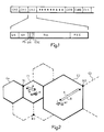
- the mobiles can transmit radio signals on a plurality of channels within the frequency range 890-915 MHz. Transmission on the channels is divided into frames and time slots according to Figure 1, such that each frame has a duration of approximately 8 ms and has 10 slots, each with a duration of 0.8 ms.
- One or a small number of the channels is used in the base stations for co-ordinated control and transmission of general information to the mobiles.
- the method of this invention is not primarily intended for application to this transmission direction, since there is not the same limitation on the transmission power from the base station to the mobiles as there is for the other direction.
- a mobile can transmit a burst, the contents of which may be situated in the slot CH2 in Figure 1.
- the information transmission rate for a burst from a mobile is 340 kb/s, and a 0.8 ms slot thus accomodate 272 bits.
- a first part GS with a duration corresponding to 28 bits is utilised as a guard space for reliably separating bursts in different slots from each other.
- a first part of the burst, corresponding to 38 bits is used for synchronising patterns SW and FS.
- a part DM corresponding to 8 bits is used for control information or packet data, and a part B m corresponding to 128 bits is used for a speech channel or the like.
- Fault correcting coding is applied, both for control information or packet data and for the speech channel and the like, which requires a part EDC corresponding to 6 bits, and a part FEC corresponding to 64 bits.
- EDC corresponding to 6 bits
- FEC corresponding to 64 bits.
- FIG. 2 illustrates a part of a mobile, cellular radio system in which the inventive method is applied.
- the cells C0 and C1 are small cells, and are assumed to cover a densely populated area, e.g. a suburban or urban area where the subscriber density is great.
- the base station B1 is common to the two small cells C0 and C1, and a mobile M in the cell C1 is assumed to communicate with another stationary or mobile subscriber (not more closely illustrated). Since the number of subscribers in the areas of cells C0 and C1 is great, there is small probability that there is any unoccupied space, i.e. an unoccupied slot in each frame on the channels over which communication to and from the mobile takes place.
- the inventive method is therefore not applicable to this area, and neither is there any need to increase the output power of the mobile.
- the large cells C2, C3 are also included in the system, these cells covering a larger area than cells C0 and C1.
- the subscriber density for each of the cells C2 and C3 is assumed to be so low that it is lower than that for either of cells C0, C1. Accordingly, a base station B2 can serve greater area than B1, but fewer mobile subscribers.
- a mobile M1 in cell C2 can be so far from the base station B2 that the signals it sends (direction B) are not sufficiently strong on reception at B2 for them to be detected reliably.
- the output power of the mobile must therefore be increased, which can involve difficulties with respect to limited possibilities of providing the mobile with a sufficient power feed to its transmitter.
- the signal sent from the base station B2 to the mobile M1 can be sufficiently strong for detection by the mobile M1, and in such a case the method does not need to be utilised in this communication direction (direction A in Figure 2).
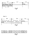
- Figure 3 illustrates in more detail the bit flow in a slot in a frame for a given channel, followed by an empty slot, e.g. corresponding to the slots CH1 and CH2 in Figure 1.
- the slots only take up 24 bit positions.
- the channel is utilised for communication within the cell C2 area, and according to what has been said above, occupation is so low that there the probability of there being an empty slot is great. It is therefore assumed that the slot CH2 is the empty one, but it could equally as well be slot CH3, or any other slot.
- Figure 4 illustrates more closely the principle of the inventive method applied to the bit flow of Figure 3.
- Both Figure 3 and Figure 4 show a radio channel at disposal for communication from a mobile to a base station, e.g. from M1 to B2.
- a control signal is sent from B2 to the mobile, this signal causing the mobile's bit frequency to change.
- This signal is received by the mobile with some form of time indication just before the slot CH1 (according to Figure 4) allotted to the mobile is about to be transmitted, and the control signals is placed in the field DM, for instance.
- the pulse frequency of the bit flow is changed so that the next following slot CH2 is completely filled with the bit positions which were earlier associated with slot 1 (see Figure 3), i.e. the pulse frequency has been halved. This results in that the energy content for each bit position has been doubled, thus increasing the range of the signals from the mobile M1 to the base station.
- the base station B2 measures the field strength received from the mobile M1 transmitter continously, and thus apprehends whether the mobile moves further away or nearer to the base station. In the latter case it is suitable for the base station B2 to send a lower value for m , i.e. the value is made adaptive in response to the distance of the mobile from the base station.
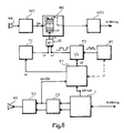
- FIG. 6 is a block diagram of the part of a mobile in which the inventive method is applied.
- the mobile has transmitting and receiving sides, and its basic units are described in such as the Swedish patent application 8703796-6.
- the transmission side includes a microphone MK or other means for taking up sound connected to a block SCC, which includes here a speech encoder, for sampling and digitalising sound signals from the means MK, and a channel encoder in which an interleaved fault-correcting coding is made of the digital signals from the speech encoder.
- the timing of the bursts is controlled by a time slot counter TC.
- a memory unit M in the burst generator BG for feeding in and storing the different bits of the digital signal ss, and the unit M is controllable such that in response to the control signal sm the stored bit flow to a following modulator MOD is started and stopped at the feed-out instants.
- the modulator is conventionally connected to the mobile's antenna via an amplifying unit and a transmit/receive switch (not shown in Figure 6).
- the transmitting side has been supplemented by a frequency divider FD, the output of which is connected to a clock input on the memory unit M in the burst generator, and its input is connected to a master clock MC.
- This clock is already available in the mobile, inter alia for timing its control processor CT.
- the timing is derived from the pulses of the master clock for when the burst generator feeds out the individual data bits in each time slot, i.e. the rate at which the information transmission takes place, e.g. 340 kb/s.
- the receiving side of the mobile contains a block D, which includes a high-frequency part, a coherent demodulator and an analogue-digital (AD) converter, known per se, and conventionally connected as described in the above-mentioned application.
- an equalizer in Block D for conventionally adapting the received, regenerated data signals and correcting deficiencies in the transmission medium (time dispersion).
- the block CD represents a channel decoder which can execute fault-correcting decoding of the signals from the equaliser in block D.
- the channel decoder CD here generates decoded digital signals with an information transmission rate of 16 kb/s.
- the channel decoder CD is connected to a speech decoder SD, which generates an analogue signal to a sound reproducing means HK in response to the decoded digital signals from the channel decoder.
- the signals which are available at the output of the channel decoder contain correct information from the base station in the appropriate time slot for the mobile, i.e. they contain the information DM, EDC, Bm and FEC.
- the part Bm is reserved for the actual call information and FEC for its fault correction.
- the field EDC in Figure 1 is normally reserved for parity bits for DM fault correction, but when necessary it can be used for transmitting the required control information to the slot counter TC from the mobile's control processor CT.
- the signal sk obtained from the output signal of the decoder CD thus also contains control data for the control processor CT, which in turn sends a control signal sc to the slot counter TC.
- the control signal sc gives the start and stop instants for a slot, and is obtained as a result of the evaluation of the signal sk by the control processor CT.
- There is namely in this signal information as to the number of slots that are empty in a frame, apart from the slot normally assigned to the mobile. Information as to the unoccupied slots in the frame can be given by the slot numbers of these extra slots (which can be put in as binary levels in the signal sk).
- the control processor CT is conventionally given a synchronising signal sd corresponding to the field sw (see Figure 1) from the block D, and it also knows the time interval for a slot CH0-CH9.
- a control signal sc can thus be produced from the control signals sd (SW) and sk and is taken to the slot couter TC, which gives start and stop instants for the normally assigned slot, e.g. CH1, and for the extra slots (CH3,CH8 in the example of Figure 5).
- the output signal st from the slot counter TC consists, for example, of a "one" for the duration of a slot.
- the frequency divider FD With its input connected to the output of mobile's master clock MC for dividing down the bit frequency during the slots which are assigned (normal plus extra) in the inventive method.
- the master clock MC is normally used for sending timing pulses or clock information to the control processor CT.
- the division factor of the frequency divider FD is controlled by the processor CT so that the division takes place in the right frame and for the slots which have been assigned to the mobile.
- the control signal sf to the divider can be the same as sc to the slot counter, since it contains information on the start and stop positions, or it can be a signal obtained from sc after processing in the control processor for obtaining information as to the correct division factor.
- Figure 6 shows the latter case i.e. the signal sf contains information as to start/stop and the division factor for the divider FD.
- the signal sr from the frequency divider FD thus gives the bit frequency during the normally assigned slot CH1 as well as the extra slots CH3, CH8.
- the mobile can, for example, have moved towards or away from the base station.
Landscapes
- Engineering & Computer Science (AREA)
- Computer Networks & Wireless Communication (AREA)
- Signal Processing (AREA)
- Mobile Radio Communication Systems (AREA)
- Radar Systems Or Details Thereof (AREA)
Applications Claiming Priority (2)
| Application Number | Priority Date | Filing Date | Title |
|---|---|---|---|
| SE8800927A SE460749B (sv) | 1988-03-15 | 1988-03-15 | Foerfarande att oeverfoera datainformation i ett cellindelat mobilradiokommunikationssystem |
| SE8800927 | 1988-03-15 |
Publications (2)
| Publication Number | Publication Date |
|---|---|
| EP0333679A1 EP0333679A1 (en) | 1989-09-20 |
| EP0333679B1 true EP0333679B1 (en) | 1992-05-27 |
Family
ID=20371694
Family Applications (1)
| Application Number | Title | Priority Date | Filing Date |
|---|---|---|---|
| EP89850039A Expired - Lifetime EP0333679B1 (en) | 1988-03-15 | 1989-02-08 | Method of transmitting data information in a mobile, cellular radio communication system |
Country Status (8)
| Country | Link |
|---|---|
| US (1) | US4972506A (no) |
| EP (1) | EP0333679B1 (no) |
| DE (1) | DE68901624D1 (no) |
| DK (1) | DK168680B1 (no) |
| ES (1) | ES2032138T3 (no) |
| FI (1) | FI85789C (no) |
| NO (1) | NO174229C (no) |
| SE (1) | SE460749B (no) |
Families Citing this family (59)
| Publication number | Priority date | Publication date | Assignee | Title |
|---|---|---|---|---|
| US5127100A (en) * | 1989-04-27 | 1992-06-30 | Motorola, Inc. | Digital radio communication system and two way radio |
| SE464438B (sv) * | 1989-08-25 | 1991-04-22 | Eritel Ab | Foerfarande foer att anpassa radiokommunikationssystem med basstation och flera mobilstationer till trafik och prestandakrav |
| SE500157C2 (sv) * | 1989-09-13 | 1994-04-25 | Ericsson Telefon Ab L M | Förfarande för att välja basstation, radiokanal och tidslucka vid en mobilstation |
| SE464955B (sv) * | 1989-11-03 | 1991-07-01 | Ericsson Telefon Ab L M | Foerfarande att indela en ramstruktur i en mobilstation |
| EP0437835B1 (en) * | 1989-12-27 | 1995-04-26 | Nec Corporation | Frame synchronization system among multiple radio base stations for TDMA digital mobile communication system |
| US5185739A (en) * | 1990-02-27 | 1993-02-09 | Motorola, Inc. | Time-allocation of radio carriers |
| CA2094710C (en) * | 1990-10-23 | 1998-12-01 | Robert Clyde Dixon | Method and apparatus for establishing spread spectrum communications |
| JPH04170825A (ja) * | 1990-11-05 | 1992-06-18 | Toshiba Corp | 無線通信方式 |
| GB2254971B (en) * | 1991-03-07 | 1994-12-21 | Ericsson Telefon Ab L M | Mobile radio communications stations |
| JPH04287462A (ja) * | 1991-03-18 | 1992-10-13 | Fujitsu Ltd | コードレス電話機及び該電話機を備えたコードレス電話システム |
| US5369637A (en) * | 1991-04-03 | 1994-11-29 | U.S. Philips Corporation | Signal transmission system |
| US5210771A (en) * | 1991-08-01 | 1993-05-11 | Motorola, Inc. | Multiple user spread-spectrum communication system |
| US5299235A (en) * | 1991-09-10 | 1994-03-29 | Telefonaktiebolaget L M Ericsson | Time synchronization of a receiver in a digital radio telephone system |
| FR2681489B1 (fr) * | 1991-09-17 | 1993-12-10 | Matra Communication | Station d'installation de communication a acces multiple par repartition dans le temps. |
| US6101177A (en) * | 1992-03-30 | 2000-08-08 | Telefonaktiebolaget Lm Ericsson | Cell extension in a cellular telephone system |
| US5260943A (en) * | 1992-06-16 | 1993-11-09 | Motorola, Inc. | TDM hand-off technique using time differences |
| JP2856232B2 (ja) * | 1992-06-30 | 1999-02-10 | 日本電気株式会社 | 無線送信装置 |
| US5337345A (en) * | 1992-07-29 | 1994-08-09 | Novatel Communications | System for securing mobile telephones from unauthorized transmission |
| FI91700C (fi) * | 1992-08-14 | 1994-07-25 | Nokia Telecommunications Oy | Menetelmä pakettidatan siirtämiseksi sekä liikkuva asema solukkoradiojärjestelmää varten |
| FI91699C (fi) * | 1992-08-14 | 1994-07-25 | Nokia Telecommunications Oy | Menetelmä käyttäjädatan siirtämiseksi pakettimuodossa solukkoradiojärjestelmässä sekä liikkuva asema |
| JP3187190B2 (ja) * | 1993-02-18 | 2001-07-11 | 株式会社東芝 | 移動無線通信システムとその基地局 |
| CA2113750C (en) * | 1993-04-30 | 1999-08-24 | Hamid Ahmadi | A multiaccess scheme for mobile integrated local area networks |
| US5517503A (en) * | 1993-06-11 | 1996-05-14 | Motorola, Inc. | Apparatus for and method of temporary termination of a communication resource |
| FI97517C (fi) * | 1993-09-06 | 1996-12-27 | Nokia Mobile Phones Ltd | Pakettidatan siirto digitaalisessa solukkoverkossa |
| US5353303A (en) * | 1993-10-04 | 1994-10-04 | The United States Of America As Represented By The Secretary Of The Air Force | Technique for increasing the data rate in a spread spectrum data link |
| US5465253A (en) * | 1994-01-04 | 1995-11-07 | Motorola, Inc. | Method and apparatus for demand-assigned reduced-rate out-of-band signaling channel |
| US5553074A (en) * | 1994-03-04 | 1996-09-03 | Trustees Of Columbia University In The City Of New York | Transmission format in packet based communications |
| FI941072A (fi) * | 1994-03-07 | 1995-09-08 | Nokia Mobile Phones Ltd | Tiedonsiirtomenetelmä, lähetin sekä vastaanotin |
| FR2718906B1 (fr) | 1994-04-13 | 1996-05-24 | Alcatel Mobile Comm France | Procédé d'adaptation de l'interface air, dans un système de radiocommunication avec des mobiles, station de base, station mobile et mode de transmission correspondants. |
| FI98426C (fi) * | 1994-05-03 | 1997-06-10 | Nokia Mobile Phones Ltd | Järjestelmä pakettidatan siirtämiseksi digitaalisen aikajakomonikäyttöön TDMA perustuvan solukkojärjestelmän ilmarajapinnassa |
| FI96468C (fi) * | 1994-05-11 | 1996-06-25 | Nokia Mobile Phones Ltd | Liikkuvan radioaseman kanavanvaihdon ohjaaminen ja lähetystehon säätäminen radiotietoliikennejärjestelmässä |
| FI98427C (fi) * | 1994-06-08 | 1997-06-10 | Nokia Mobile Phones Ltd | Järjestelmäpakettidatan siirtämiseksi eri bittinopeuksilla TDMA-solukkojärjestelmässä |
| FI97095C (fi) * | 1994-10-31 | 1996-10-10 | Nokia Mobile Phones Ltd | TDMA-signaalien kehysajastuksen ohjaus |
| US5675590A (en) * | 1994-11-23 | 1997-10-07 | At&T Wireless Services, Inc. | Cyclic trellis coded modulation |
| US5659578A (en) * | 1994-11-23 | 1997-08-19 | At&T Wireless Services, Inc. | High rate Reed-Solomon concatenated trellis coded 16 star QAM system for transmission of data over cellular mobile radio |
| US6889356B1 (en) * | 1994-11-23 | 2005-05-03 | Cingular Wireless Ii, Llc | Cyclic trellis coded modulation |
| FI97504C (fi) * | 1994-12-19 | 1996-12-27 | Nokia Telecommunications Oy | Tiedonsiirtomenetelmä, tiedonsiirtojärjestelmä ja solukkoradiojärjestelmä |
| US5719859A (en) * | 1995-09-19 | 1998-02-17 | Matsushita Electric Industrial Co., Ltd. | Time division multiple access radio communication system |
| US5774461A (en) * | 1995-09-27 | 1998-06-30 | Lucent Technologies Inc. | Medium access control and air interface subsystem for an indoor wireless ATM network |
| SE504577C2 (sv) * | 1996-02-16 | 1997-03-10 | Ericsson Telefon Ab L M | Metod och anordning för kanaltilldelning i ett radiokommunikationssystem |
| JPH09298521A (ja) * | 1996-05-08 | 1997-11-18 | Nec Eng Ltd | 無線中継制御方法及び無線通信中継制御方式 |
| GB2321160B (en) * | 1996-12-09 | 2001-05-16 | Nokia Mobile Phones Ltd | Packet data |
| US6236855B1 (en) * | 1997-05-01 | 2001-05-22 | Bellsouth Intellectual Property Management Corporation | Method for voice quality improvement in a wireless transmission system |
| EP0901241B1 (de) | 1997-09-08 | 2009-01-28 | Infineon Technologies AG | Digitale Telekommunikationseinrichtung mit Mobilteil und TDMA Verfahren |
| DE19752197A1 (de) | 1997-11-25 | 1999-05-27 | Siemens Ag | Übertragungssystem zur Übertragung von Digitalsignalen in einem Funk-Teilnehmeranschlußnetz |
| FI106607B (fi) * | 1998-01-07 | 2001-02-28 | Nokia Mobile Phones Ltd | Solun valinta usean modulaation solukkoradiojärjestelmässä |
| GB9805860D0 (en) * | 1998-03-20 | 1998-05-13 | Philips Electronics Nv | Timing control of transmission time slot |
| FI112841B (fi) * | 1999-06-01 | 2004-01-15 | Nokia Corp | Menetelmä ja järjestely yhteyden muodostamiseksi tukiaseman ja matkaviestimen välille sekä matkaviestin |
| DE19931236C2 (de) | 1999-07-07 | 2002-05-29 | Siemens Ag | Verfahren zur Zuweisung von Übertragungskapazität zu Verbindungen in einem Funk-Kommunikationssystem |
| US6480472B1 (en) * | 1999-07-21 | 2002-11-12 | Qualcomm Incorporated | Mobile station supervision of the forward dedicated control channel when in the discontinuous transmission mode |
| AU6674000A (en) | 1999-08-11 | 2001-03-13 | Mark Iv Industries Limited | Method and means for rf toll collection |
| EP2571324A3 (en) | 2004-04-30 | 2013-05-08 | Mitsubishi Denki Kabushiki Kaisha | Transmission timing control per communication service |
| US7512236B1 (en) | 2004-08-06 | 2009-03-31 | Mark Iv Industries Corporation | System and method for secure mobile commerce |
| US7233260B2 (en) | 2004-10-05 | 2007-06-19 | Mark Iv Industries Corp. | Electronic toll collection system |
| US7262711B2 (en) | 2004-10-20 | 2007-08-28 | Mark Iv Industries Corp. | External indicator for electronic toll communications |
| CA2544595A1 (en) | 2005-04-22 | 2006-10-22 | Mark Iv Industries Corp. | Open road vehicle emissions inspection |
| US7385525B2 (en) | 2005-07-07 | 2008-06-10 | Mark Iv Industries Corporation | Dynamic timing adjustment in an electronic toll collection system |
| US7342500B2 (en) | 2006-03-24 | 2008-03-11 | Mark Iv Industries, Corp. | Compact microstrip transponder antenna |
| US7388501B2 (en) | 2006-05-19 | 2008-06-17 | Mark Iv Industries Corp | Method of enabling two-state operation of electronic toll collection system |
Family Cites Families (10)
| Publication number | Priority date | Publication date | Assignee | Title |
|---|---|---|---|---|
| DE2527323C3 (de) * | 1975-06-19 | 1978-10-12 | Standard Elektrik Lorenz Ag, 7000 Stuttgart | Multiplexer eines digitalen Zeitmultiplex-Übertragungssystems mit einer von der eingangsseitigen Beschattung abhängigen Ausgangsbitrate |
| JPS5810022B2 (ja) * | 1978-05-24 | 1983-02-23 | 富士通株式会社 | 時分割多重回線割当て制御方式 |
| NL189062C (nl) * | 1980-02-15 | 1992-12-16 | Philips Nv | Werkwijze en stelsel voor overdracht van datapakketten. |
| DE3527329A1 (de) * | 1985-07-31 | 1987-02-05 | Philips Patentverwaltung | Digitales funkuebertragungssystem mit variabler zeitschlitzdauer der zeitschlitze im zeitmultiplexrahmen |
| US4792948A (en) * | 1985-08-08 | 1988-12-20 | Data General Corporation | Distributed switching architecture |
| EP0214319B1 (de) * | 1985-09-02 | 1989-08-02 | ANT Nachrichtentechnik GmbH | Verfahren zum Weiterreichen einer Mobilstation von einer Funkzelle zu einer anderen |
| EP0219559B1 (de) * | 1985-10-17 | 1990-09-05 | ANT Nachrichtentechnik GmbH | Mobilfunksystem für die Übertragung sowohl digitaler als auch analoger Signale |
| US4797947A (en) * | 1987-05-01 | 1989-01-10 | Motorola, Inc. | Microcellular communications system using macrodiversity |
| US4785450B1 (en) * | 1987-08-06 | 1999-10-12 | Interdigital Tech Corp | Apparatus and method for obtaining frequency agility in digital communication system |
| US4866710A (en) * | 1988-02-22 | 1989-09-12 | Motorola, Inc. | Reuse groups for scan monitoring in digital cellular systems |
-
1988
- 1988-03-15 SE SE8800927A patent/SE460749B/sv not_active IP Right Cessation
-
1989
- 1989-02-08 ES ES198989850039T patent/ES2032138T3/es not_active Expired - Lifetime
- 1989-02-08 EP EP89850039A patent/EP0333679B1/en not_active Expired - Lifetime
- 1989-02-08 DE DE8989850039T patent/DE68901624D1/de not_active Expired - Lifetime
- 1989-02-17 FI FI890781A patent/FI85789C/sv not_active IP Right Cessation
- 1989-02-17 US US07/311,900 patent/US4972506A/en not_active Expired - Lifetime
- 1989-03-13 NO NO891070A patent/NO174229C/no not_active IP Right Cessation
- 1989-03-14 DK DK123589A patent/DK168680B1/da not_active IP Right Cessation
Non-Patent Citations (1)
| Title |
|---|
| Funkschau, no. 1/1985; M. Böhm/Schaller/Kp.: "Digitales Mobilfunksystem für jedermann" * |
Also Published As
| Publication number | Publication date |
|---|---|
| ES2032138T3 (es) | 1993-01-01 |
| NO174229C (no) | 1994-03-30 |
| DK123589D0 (da) | 1989-03-14 |
| US4972506A (en) | 1990-11-20 |
| NO891070L (no) | 1989-09-18 |
| FI85789C (sv) | 1992-05-25 |
| SE460749B (sv) | 1989-11-13 |
| SE8800927D0 (sv) | 1988-03-15 |
| DE68901624D1 (de) | 1992-07-02 |
| EP0333679A1 (en) | 1989-09-20 |
| DK168680B1 (da) | 1994-05-16 |
| FI890781A (fi) | 1989-09-16 |
| NO174229B (no) | 1993-12-20 |
| FI85789B (fi) | 1992-02-14 |
| FI890781A0 (fi) | 1989-02-17 |
| DK123589A (da) | 1989-09-16 |
| SE8800927L (sv) | 1989-09-16 |
| NO891070D0 (no) | 1989-03-13 |
Similar Documents
| Publication | Publication Date | Title |
|---|---|---|
| EP0333679B1 (en) | Method of transmitting data information in a mobile, cellular radio communication system | |
| US5648967A (en) | Method and arrangement for transmitting information in a digital radio system | |
| US4628506A (en) | Method for transmitting communications services via satellites | |
| RU2341038C2 (ru) | Радиотелефонная система для групп удаленных абонентов | |
| US6411613B1 (en) | Method for formatting and conveying information in a wireless telecommunication system | |
| US5822315A (en) | Air interface adapting method for a mobile radio system | |
| US5373502A (en) | Process, transmitter and receiver for data transmission with variable traffic volume and a control station for coordinating several such transmitters and receivers | |
| US5563895A (en) | Digital mobil E radio communication system | |
| US6026083A (en) | Transmission of control messages in digital telephony | |
| US6061340A (en) | Transmission of digital data messages in digital telephony | |
| JP4024859B2 (ja) | デジタル通信装置によって生成された干渉を減少させるシステムおよび方法 | |
| MXPA97002010A (en) | Transmission of digital data messages in telefonia digi | |
| CA2246433A1 (en) | Method and apparatus for dynamically selecting the length of mobile station burst communications on the reverse digital control channel | |
| US6044086A (en) | Control signal transmission in digital radio telephony | |
| EP0031486B1 (en) | Apparatus to reduce the effect of a mid-talkspurt freeze-out | |
| US4873684A (en) | Method and apparatus for multiplexing of input signals having differing frequencies and demultiplexing same | |
| JP3444901B2 (ja) | データの有効な無線伝送のための方法及び装置 | |
| US7577116B2 (en) | Timeslot assignment mechanism for satellite communication network | |
| CA1320013C (en) | Arrangement for transforming data packets into a regular multiplex for a transmission system utilizing the tdma principle | |
| WO1996019086A1 (en) | A traffic channel arrangement using two time slots in a mobile telephone system | |
| EP0629094B1 (en) | Improvements in or relating to cellular mobile radio systems | |
| US20030108023A1 (en) | Data transmission in a communication system | |
| EP1063860B1 (en) | Method and system for multiple acess in a radiocommunication system | |
| EP2061163A1 (en) | Timeslot assignment mechanism for satellite communication network | |
| CN1211949C (zh) | 无线电传输的方法和装置 |
Legal Events
| Date | Code | Title | Description |
|---|---|---|---|
| PUAI | Public reference made under article 153(3) epc to a published international application that has entered the european phase |
Free format text: ORIGINAL CODE: 0009012 |
|
| AK | Designated contracting states |
Kind code of ref document: A1 Designated state(s): CH DE ES FR GB IT LI NL |
|
| 17P | Request for examination filed |
Effective date: 19891006 |
|
| 17Q | First examination report despatched |
Effective date: 19910830 |
|
| GRAA | (expected) grant |
Free format text: ORIGINAL CODE: 0009210 |
|
| AK | Designated contracting states |
Kind code of ref document: B1 Designated state(s): CH DE ES FR GB IT LI NL |
|
| REF | Corresponds to: |
Ref document number: 68901624 Country of ref document: DE Date of ref document: 19920702 |
|
| ITF | It: translation for a ep patent filed |
Owner name: FUMERO BREVETTI S.N.C. |
|
| ET | Fr: translation filed | ||
| REG | Reference to a national code |
Ref country code: ES Ref legal event code: FG2A Ref document number: 2032138 Country of ref document: ES Kind code of ref document: T3 |
|
| PLBE | No opposition filed within time limit |
Free format text: ORIGINAL CODE: 0009261 |
|
| STAA | Information on the status of an ep patent application or granted ep patent |
Free format text: STATUS: NO OPPOSITION FILED WITHIN TIME LIMIT |
|
| 26N | No opposition filed | ||
| PGFP | Annual fee paid to national office [announced via postgrant information from national office to epo] |
Ref country code: CH Payment date: 20010122 Year of fee payment: 13 |
|
| REG | Reference to a national code |
Ref country code: GB Ref legal event code: IF02 |
|
| PGFP | Annual fee paid to national office [announced via postgrant information from national office to epo] |
Ref country code: NL Payment date: 20020121 Year of fee payment: 14 |
|
| PG25 | Lapsed in a contracting state [announced via postgrant information from national office to epo] |
Ref country code: CH Free format text: LAPSE BECAUSE OF NON-PAYMENT OF DUE FEES Effective date: 20020228 Ref country code: LI Free format text: LAPSE BECAUSE OF NON-PAYMENT OF DUE FEES Effective date: 20020228 |
|
| REG | Reference to a national code |
Ref country code: CH Ref legal event code: PL |
|
| PG25 | Lapsed in a contracting state [announced via postgrant information from national office to epo] |
Ref country code: NL Free format text: LAPSE BECAUSE OF NON-PAYMENT OF DUE FEES Effective date: 20030901 |
|
| NLV4 | Nl: lapsed or anulled due to non-payment of the annual fee |
Effective date: 20030901 |
|
| PG25 | Lapsed in a contracting state [announced via postgrant information from national office to epo] |
Ref country code: IT Free format text: LAPSE BECAUSE OF NON-PAYMENT OF DUE FEES;WARNING: LAPSES OF ITALIAN PATENTS WITH EFFECTIVE DATE BEFORE 2007 MAY HAVE OCCURRED AT ANY TIME BEFORE 2007. THE CORRECT EFFECTIVE DATE MAY BE DIFFERENT FROM THE ONE RECORDED. Effective date: 20050208 |
|
| PGFP | Annual fee paid to national office [announced via postgrant information from national office to epo] |
Ref country code: ES Payment date: 20080226 Year of fee payment: 20 |
|
| PGFP | Annual fee paid to national office [announced via postgrant information from national office to epo] |
Ref country code: GB Payment date: 20080227 Year of fee payment: 20 |
|
| PGFP | Annual fee paid to national office [announced via postgrant information from national office to epo] |
Ref country code: FR Payment date: 20080218 Year of fee payment: 20 Ref country code: DE Payment date: 20080331 Year of fee payment: 20 |
|
| REG | Reference to a national code |
Ref country code: GB Ref legal event code: PE20 Expiry date: 20090207 |
|
| REG | Reference to a national code |
Ref country code: ES Ref legal event code: FD2A Effective date: 20090209 |
|
| PG25 | Lapsed in a contracting state [announced via postgrant information from national office to epo] |
Ref country code: GB Free format text: LAPSE BECAUSE OF EXPIRATION OF PROTECTION Effective date: 20090207 |
|
| PG25 | Lapsed in a contracting state [announced via postgrant information from national office to epo] |
Ref country code: ES Free format text: LAPSE BECAUSE OF EXPIRATION OF PROTECTION Effective date: 20090209 |