EP0333615B1 - Méthode pour établir les nombres de groupes de transmission dans les lignes d'un réseau - Google Patents
Méthode pour établir les nombres de groupes de transmission dans les lignes d'un réseau Download PDFInfo
- Publication number
- EP0333615B1 EP0333615B1 EP89480013A EP89480013A EP0333615B1 EP 0333615 B1 EP0333615 B1 EP 0333615B1 EP 89480013 A EP89480013 A EP 89480013A EP 89480013 A EP89480013 A EP 89480013A EP 0333615 B1 EP0333615 B1 EP 0333615B1
- Authority
- EP
- European Patent Office
- Prior art keywords
- transmission group
- node
- group number
- nodes
- zero
- Prior art date
- Legal status (The legal status is an assumption and is not a legal conclusion. Google has not performed a legal analysis and makes no representation as to the accuracy of the status listed.)
- Expired - Lifetime
Links
Images


Classifications
-
- H—ELECTRICITY
- H04—ELECTRIC COMMUNICATION TECHNIQUE
- H04L—TRANSMISSION OF DIGITAL INFORMATION, e.g. TELEGRAPHIC COMMUNICATION
- H04L41/00—Arrangements for maintenance, administration or management of data switching networks, e.g. of packet switching networks
-
- H—ELECTRICITY
- H04—ELECTRIC COMMUNICATION TECHNIQUE
- H04L—TRANSMISSION OF DIGITAL INFORMATION, e.g. TELEGRAPHIC COMMUNICATION
- H04L9/00—Cryptographic mechanisms or cryptographic arrangements for secret or secure communications; Network security protocols
- H04L9/40—Network security protocols
-
- H—ELECTRICITY
- H04—ELECTRIC COMMUNICATION TECHNIQUE
- H04L—TRANSMISSION OF DIGITAL INFORMATION, e.g. TELEGRAPHIC COMMUNICATION
- H04L69/00—Network arrangements, protocols or services independent of the application payload and not provided for in the other groups of this subclass
- H04L69/24—Negotiation of communication capabilities
Definitions
- the present invention relates to communication networks and more particularly to a method for permitting two partner nodes to dynamically establish a transmission group number used to identify a link between the two nodes.
- the communications network can generally be defined as a collection of network nodes which are interconnected through communications links.
- a network node can be characterized as a data processing system that provides certain functions within the network, such as routing of messages between itself and its adjacent or neighboring nodes, selection of routes for messages to be transmitted between a network node and a directly-connected peripheral node and the furnishing of directory services to peripheral nodes.
- the links between nodes may be permanent communications links, such as conventional cable connections, or links that are enabled only when needed, such as dial-up telephone connections.
- a link is identified by concatenating network-qualified names for the two nodes connected by the link with a number assigned to a transmission group for connection between the two nodes.
- a network-qualified node name is a name which is known to be unique in the network.
- node names are unique within the network, a given link between two nodes is unambiguously identified by any given transmission group number applied to a link between the two nodes. Ambiguity is created where the same transmission group number is applied to more than one of several parallel links which can be used to connect the nodes.
- a transmission group number is assigned to each link between two partner nodes when the system is initially defined or when one or both of the nodes are added to the network.
- the present invention eliminates the requirement that transmission group numbers be assigned during system definition/reconfiguration by allowing two paired or partner nodes to dynamically establish a unique transmission group number for each link between the nodes.
- the method is performed at each of the two nodes during initialization of a connection. Each node sends an exchange identification message to the remote node.
- the method includes a proposed exchange identification message to the other node.
- a message includes a proposed non-zero transmission group number if one had been previously defined or a zero transmission group number if no non-zero number has been previously defined.
- Each node determines the value of the transmission group number contained in the message received from the remote node.
- the non-zero number is selected by both nodes. If both nodes send zeros or both send non-zero numbers, both nodes compare the relative significance of their node names according to predetermined criteria. The node having the most significant node name is selected. The selected node assigns a final non-zero transmission group number.
- a simple data communications network 10 is shown as having three nodes 12, 14 and 16 interconnected through links 18, 20 and 22.
- link 18 as an example, each link includes a link connection which provides a connection between a first link station 26 in one of the nodes and the second link station 28 in the other of the nodes.
- the link connection represents the physical medium, such as telephone wire or a microwave beam used to transmit data between the two link stations in the nodes.
- Expanded definitions of these terms may be found in a number of publications, including Systems Network Architecture Concepts and Product (No. GC30-3072), Systems Network Architecture Technical Overview(No GC30-3073) and System Network Architecture Format and Protocol Reference Manual : Architecture Logic for Type 2.1 Nodes (No SC30-3422). While these publications may be useful to a reader, they are not essential to an understanding of the invention.
- the function of the data communications network is to establish and maintain routes or paths which allow two end users to exchange data through the network.
- An end user may either be an individual at a workstation, such as any of a number of workstations 30 connected to the different nodes in the network, or an application for transaction program, such as program 32 connected to node 12 or program 34 connected to node 16.
- Each end user is connected to the network through a logical unit or LU which manages the exchange of data. LUs are connected in a mutual relationship called a session.
- An example of a logical unit or LU is LU 36 in node 12.
- each link in the route between the end users requires that each link in the route between the end users be unambiguously identified. For example, if an operator at workstation 30 was to communicate with the application program 32 at node 12, either of two routes could be specified. The more direct route would be through link 18 connecting nodes 12 and 14. An indirect route, which might be needed if link 18 were unavailable would be through link 20 connecting nodes 14 and 16 and then link 22, connecting nodes 16 and 12. Each of these links must be identified to the two nodes at opposite ends of the link. These two nodes may be referred to herafter as paired or partner nodes since each has responsibilities in establishing and maintaining the link.
- the link identification is a concatenated word consisting of the names of each of the two partner nodes in combination with the transmission group number, which is a number used to identify what is usually one of several possible link connections between the same two nodes.
- the prior art practice was to assign a transmission group number to each possible line between two nodes at the time of system definition.
- Figure 2 is a short flow chart which provides an overview of the process of establishing a transmission group number.
- both nodes propose a transmission group number (block 40) in a transmission of exchange identification (XID) to the other node.
- XID exchange identification
- An XID message is used by a given node to convey node and link characteristics to an adjacent node. It is exchanged between link sessions before and during link activation to establish and negotiate link and node characteristics.
- the format and content of XID messages are described in more detail in the earlier-referenced publications.
- the transmission group number proposed by a node may either be a zero or a non-zero number. Conditions under which a node must propose a zero transmission group number or a non-zero transmission group number are explained in more detail later.
- Each node checks (block 42) to see whether has proposed either zero transmission group numbers or non-zero transmission group numbers. If only one of the nodes has proposed a zero transmission group number, then both nodes utilize the non-zero transmission group number (block 44), regardless of which node originally proposed it. If, on the other hand, the check in block 42 indicates that both nodes proposed either a zero transmission group number or any non-zero transmission group number, then one of the two nodes must be identified as a controlling node. A preferred mechanism for identifying the controlling nodes is described in more detail later. Once the controlling node is selected, that node sets the transmission group number to be used (block 46) and transmits the selected number to the other or non-controlling node.
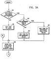
- Figure 3 consisting of Figures 3A and 3B taken together, is a more detailed flow chart of the steps performed at each of two partner nodes in order to negotiate a transmission group number acceptable to both.
- each node performs the same series of steps.
- the description refers to a transmisson group number being sent, that is the number sent by that node.
- the transmission group number sent by one node would be the transmission group number considered as having been received by the other node.
- the first step (block 48) in the process of establishing a transmission group number requires that each node check to see whether a transmission group number has already been defined for the node pair. If a number has been defined, a further check (block 50) is made to determine whether that number is already in use. If it is, the node selects a different non-zero value (block 52). If the defined number is not in use, the transmission group number is set (block 54) to the previously defined value. If check 48 shows that no transmission group number was previously defined, the node sets the proposed transmission group number equal to zero (block 56). The transmission group number selected by one of the operations 52, 54 or 56 is sent to the other node (block 58) as part of an exchange of XID three messages. As mentioned earlier, the format of XID messages in general and XID three messages, in particular, is more fully set forth in the referenced publications.
- a check is made to determine whether the transmission group number proposed by the other node is equal to zero. Assuming the results of check 62 are positive, a further check (block 64) is made to determine whether the transmission group number proposed by the local node is also equal to zero. If the local node proposed a non-zero number, that non-zero number is selected (block 66) as the final transmission group number. Under those conditions, it is not necessary for the local node to inform the remote node of the selected transmission group number. The remote node will, by performing the operations set forth in Figure 3, make its own determination that the non-zero transmission group number should be finally selected.
- check 64 indicates that the transmission group numbers set by the local node is zero, meaning that both nodes have proposed zero transmission group numbers, it is necessary to choose a controlling node which will assume the responsibility of selecting a non-zero transmission group number.
- the first step in choosing a controlling node is to compare the relative value of the network-qualified node names (block 68) according to some predetermined criteria. Since both nodes are, by definition, in the same network and since the network-qualified node name for any given node is unique within that network, the comparison performed will always show that one of the two nodes has a more "significant" name according to some criteria. A preferred method of choosing the controlling node will be described later.
- the local node would, in essence, defer to the remote node since the remote node would have assumed the responsibility for selecting a final transmission group number and transmitting that number.
- a further check is made to determine whether the transmission group number proposed by the local node is equal to zero. If the locally proposed transmission group number was equal to zero, the local node would set the final transmission group number equal to the number received from the other node (block 78) before leaving the program. If the checks made at blocks 62 and 76 had indicated that both nodes had proposed non-zero transmission group numbers, the relative values of the node names are compared (block 80) using the previously-mentioned criteria.
- the final transmission group number is set equal to the transmission group number proposed by the local node (block 84) before exiting the program. If decision block 82 showed that the remote node name was more significant, the local node would set the final transmission group number equal to the transmission group number proposed by the remote LU (block 86) and notify the remote node of its acquiesence by transmitting a second XID three message (block 88) to the remote node with a transmission group number equal to zero.
- That method basically uses a standard collating sequence to determine which node name has the greater value in the sequence.
- the initial step in the process (block 90) is to determine whether both the local node name and the remote node name are the same length. If they are not, the shorter node name is padded with zeros (block 92) until the lengths are equal. Once the name lengths are equal, the first byte of the local node name is compared to the first byte of the remote node name (block 92) to determine whether the bytes have the same value. Assuming they do, the byte value is altered (block 94) an check 92 repeated with the next byte in the two node names.
- a check is made (block 96) to see whether the value of the byte in the local name is greater than the value of the corresponding byte in the remote node name. If the "local byte" has a greater value in the collating sequence than the "remote byte", the local node is identified (block 98) as having the more significant node name. The local node becomes the controlling node for purposes of finally selecting a transmission group number.
- the remote node would be identified (block 100) as having the more significant value and would be selected as the controlling node.
Claims (5)
- Procédé pour établir les nombres de groupes de transmission dans un réseau de communication (10), dans lequel des paires sélectionnées de noeuds (12, 14) peuvent être sélectivement connectées directement par des groupes de transmission, chaque groupe de transmission étant uniquement identifié en fonction des noms des noeuds associés (12, 14) en combinaison avec un nombre de groupes de transmission attribué, ledit procédé permettant à l'un des noeuds d'attribuer le nombre de groupes de transmission, et étant réalisé à chacun des deux noeuds durant l'initialisation de la connexion, ledit procédé comprenant les étapes de:
envoyer (40) un message d'identification d'échange (XID) d'un premier noeud à un deuxième noeud, ledit message comprenant un nombre de groupes de transmission non-zéro proposé s'il en a été déterminé un préalablement au noeud d'envoi ou un nombre de groupes de transmission zéro si aucun nombre de groupes de transmission non-zéro n'a été déterminé préalablement,
déterminer la valeur du nombre de groupes de transmission contenu dans le message d'identification d'échange reçu à partir du deuxième noeud,
fixer le nombre de groupes de transmission final égal au nombre de groupes de transmission non-zéro proposé envoyé par l'un des premier et deuxième noeuds où l'autre des noeuds a envoyé à l'origine un nombre de groupes de transmission zéro,
comparer (68) la signification relative des premier et deuxième noms de noeud suivant des critères prédéterminés où les deux noeuds envoient soit des nombres de groupes de transmission zéro soit des nombres de groupes de transmission non-zéro proposés,
sélectionner (70) le noeud ayant le nom de noeud le plus significatif suivant les critères prédéterminés, et
permettre (72) au noeud sélectionné d'attribuer un nombre de groupes de transmission non-zéro final où les deux noeuds ont envoyé à l'origine des nombres de groupes de transmission zéro ou où les deux noeuds ont envoyé à l'origine des nombres de groupes de transmission non-zéro proposés. - Procédé selon la revendication 1, dans lequel l'étape d'envoyer un message d'identification d'échange (XID) est précédée des étapes de:
déterminer (48) si un nombre de groupes de transmission non-zéro proposé est déjà utilisé entre les premier et deuxième noeuds, et
sélectionner (50, 52) un nombre de groupes de transmission non-zéro proposé différent si le nombre proposé à l'origine est déterminé comme étant utilisé. - Procédé selon l'une ou l'autre des revendications 1 et 2, comprenant les étapes de:
faire reconnaître par le noeud non sélectionné qu'il a accepté le groupe de transmission non-zéro final en envoyant le nombre de groupes de transmission sélectionné au noeud sélectionné. - Procédé selon l'une quelconque des revendications 1, 2 ou 3, dans lequel ladite étape de sélectionner comprend les étapes de:
comparer (90, 92, 93, 94) les noms des premier et deuxième noeuds pour déterminer les valeurs relatives des noms dans une séquence de collation standard, et
sélectionner (96, 98, 100) le noeud ayant le nom de plus grande valeur. - Procédé selon la revendication 1, dans lequel l'étape d'envoyer un message d'identification d'échange XID est précédée par les étapes de:
déterminer si un nombre de groupes de transmission zéro a été transmis au deuxième noeud la première fois qu'a été amorcée une connexion entre les deux noeuds; et
envoyer un nombre de groupes de transmission non-zéro uniquement si un nombre de groupes de transmission zéro n'a pas été transmis au deuxième noeud à l'amorçage de la première connexion.
Applications Claiming Priority (2)
| Application Number | Priority Date | Filing Date | Title |
|---|---|---|---|
| US168286 | 1988-03-15 | ||
| US07/168,286 US4954821A (en) | 1988-03-15 | 1988-03-15 | Method of establishing transmission group numbers for network links |
Publications (3)
| Publication Number | Publication Date |
|---|---|
| EP0333615A2 EP0333615A2 (fr) | 1989-09-20 |
| EP0333615A3 EP0333615A3 (fr) | 1991-10-23 |
| EP0333615B1 true EP0333615B1 (fr) | 1994-10-26 |
Family
ID=22610867
Family Applications (1)
| Application Number | Title | Priority Date | Filing Date |
|---|---|---|---|
| EP89480013A Expired - Lifetime EP0333615B1 (fr) | 1988-03-15 | 1989-01-31 | Méthode pour établir les nombres de groupes de transmission dans les lignes d'un réseau |
Country Status (4)
| Country | Link |
|---|---|
| US (1) | US4954821A (fr) |
| EP (1) | EP0333615B1 (fr) |
| JP (1) | JPH0831863B2 (fr) |
| DE (1) | DE68918970T2 (fr) |
Families Citing this family (7)
| Publication number | Priority date | Publication date | Assignee | Title |
|---|---|---|---|---|
| JPH02242469A (ja) * | 1989-03-16 | 1990-09-26 | Fujitsu Ltd | 対向装置監視方式 |
| US5007052A (en) * | 1989-04-11 | 1991-04-09 | Metricom, Inc. | Method for routing packets by squelched flooding |
| US5371863A (en) * | 1991-05-30 | 1994-12-06 | Tandem Computers Incorporated | High speed processor bus extension |
| US5546587A (en) * | 1991-05-30 | 1996-08-13 | Tandem Computers Incorporated | Decentralized bus arbitration system which continues to assert bus request signal to preclude other from asserting bus request signal until information transfer on the bus has been completed |
| CA2107047C (fr) * | 1992-12-29 | 1998-04-28 | Alan M. Bentley | Gestion de connexions de circuits commutes via un reseau de donnees public pour reseaux longue distance |
| US5546549A (en) * | 1994-06-01 | 1996-08-13 | International Business Machines Corporation | Multi-path channel (MPC) interface with user transparent, unbalanced, dynamically alterable computer input/output channels |
| US9055429B2 (en) * | 2013-01-15 | 2015-06-09 | British Telecommunications Public Limited Company | Group subscriber number management system for a group messaging service |
Family Cites Families (9)
| Publication number | Priority date | Publication date | Assignee | Title |
|---|---|---|---|---|
| CA1226638A (fr) * | 1982-08-19 | 1987-09-08 | Mitsuji Takao | Transmission de donnees |
| JPS5992654A (ja) * | 1982-11-09 | 1984-05-28 | インタ−ナショナル ビジネス マシ−ンズ コ−ポレ−ション | 電子文書配送システム |
| US4785449A (en) * | 1984-05-21 | 1988-11-15 | Canon Kabushiki Kaisha | Network system for data transmission among plural communications stations connected to a communication medium |
| CA1245327A (fr) * | 1985-09-06 | 1988-11-22 | Northern Telecom Limited | Systeme et methode d'acheminement pour reseaux a commutation de paquets |
| JPH0831876B2 (ja) * | 1985-09-20 | 1996-03-27 | 株式会社日立製作所 | パケツト交換網におけるル−チング制御方式 |
| US4785396A (en) * | 1986-01-28 | 1988-11-15 | Intel Corporation | Push-pull serial bus coupled to a plurality of devices each having collision detection circuit and arbitration circuit |
| US4706082A (en) * | 1986-02-24 | 1987-11-10 | Chrysler Motors Corporation | Serial data bus for intermodule data communications |
| DE3773503D1 (de) * | 1986-02-24 | 1991-11-14 | Siemens Ag | Schaltungsanordnung fuer pcm-fernmeldeanlagen, insbesondere pcm-fernsprechvermittlungsanlagen, mit mehreren synchron pulstaktgesteuerten sendern fuer gemeinsamen sendekanal. |
| JPS63205747A (ja) * | 1987-02-13 | 1988-08-25 | インターナシヨナル・ビジネス・マシーンズ・コーポレーシヨン | 通信方法及びデータ処理システム |
-
1988
- 1988-03-15 US US07/168,286 patent/US4954821A/en not_active Expired - Lifetime
- 1988-12-16 JP JP63316623A patent/JPH0831863B2/ja not_active Expired - Fee Related
-
1989
- 1989-01-31 EP EP89480013A patent/EP0333615B1/fr not_active Expired - Lifetime
- 1989-01-31 DE DE68918970T patent/DE68918970T2/de not_active Expired - Fee Related
Also Published As
| Publication number | Publication date |
|---|---|
| EP0333615A3 (fr) | 1991-10-23 |
| US4954821A (en) | 1990-09-04 |
| DE68918970D1 (de) | 1994-12-01 |
| JPH0210947A (ja) | 1990-01-16 |
| JPH0831863B2 (ja) | 1996-03-27 |
| EP0333615A2 (fr) | 1989-09-20 |
| DE68918970T2 (de) | 1995-04-27 |
Similar Documents
| Publication | Publication Date | Title |
|---|---|---|
| EP0159810B1 (fr) | Système de transmission numérique à bande large | |
| US5050166A (en) | Transfer of messages in a multiplexed system | |
| US5790553A (en) | Seamless peer-to-peer communications in a layered communications architecture | |
| EP0348330B1 (fr) | Méthode pour la commande de sessions avec ressources limitées dans un réseau de communication de données | |
| EP0246428A2 (fr) | Procédé et système pour l'adressage et la commande d'un réseau de modems | |
| US5153876A (en) | Communication protocol for statistical data multiplexers arranged in a wide area network | |
| JPS6048638A (ja) | サ−ビス要求を探知するためのポ−リング方法 | |
| EP0261205A1 (fr) | Techniques de pontage pour reseaux locaux | |
| US5029165A (en) | Method of allotting links and routing messages for a common channel type signalling transfer point | |
| EP0333615B1 (fr) | Méthode pour établir les nombres de groupes de transmission dans les lignes d'un réseau | |
| EP0940961B1 (fr) | Procédé, dispositif et récepteur pour établir des connections dans un réseau de télécommunications à protocoles multiples | |
| US5570359A (en) | OSI transport relay system between a network in connected mode and a network in non-connected mode | |
| US5343466A (en) | Path routing system for communication network | |
| EP0818116A1 (fr) | Méthode de transfert de transmission de données | |
| US5920620A (en) | Channel establishing method of point-to-multipoint and multipoint-to-point communications | |
| CA2218850A1 (fr) | Methode de communication directionnelle avec un serveur pour cellules transmises par un module connecte a un reseau local d'acces a des stations mobiles et reseau de ce type utilisant cette methode | |
| JP2924449B2 (ja) | リンク選択方式 | |
| JPH09289523A (ja) | パケット交換中継方式 | |
| JP3345223B2 (ja) | 衛星通信方法、及び中央局、端末局 | |
| JP4150109B2 (ja) | 通信接続切替方法及び通信接続切替装置 | |
| JPH0125464B2 (fr) | ||
| AU640847B2 (en) | A network station | |
| JP3541486B2 (ja) | 同報接続制御方法 | |
| JPS6260332A (ja) | 汎用多重デ−タ伝送システム | |
| JPH0795245A (ja) | 網間接続方法及びこれを用いた通信システム |
Legal Events
| Date | Code | Title | Description |
|---|---|---|---|
| PUAI | Public reference made under article 153(3) epc to a published international application that has entered the european phase |
Free format text: ORIGINAL CODE: 0009012 |
|
| AK | Designated contracting states |
Kind code of ref document: A2 Designated state(s): DE FR GB |
|
| 17P | Request for examination filed |
Effective date: 19900120 |
|
| PUAL | Search report despatched |
Free format text: ORIGINAL CODE: 0009013 |
|
| AK | Designated contracting states |
Kind code of ref document: A3 Designated state(s): DE FR GB |
|
| 17Q | First examination report despatched |
Effective date: 19930729 |
|
| GRAA | (expected) grant |
Free format text: ORIGINAL CODE: 0009210 |
|
| AK | Designated contracting states |
Kind code of ref document: B1 Designated state(s): DE FR GB |
|
| REF | Corresponds to: |
Ref document number: 68918970 Country of ref document: DE Date of ref document: 19941201 |
|
| ET | Fr: translation filed | ||
| PLBE | No opposition filed within time limit |
Free format text: ORIGINAL CODE: 0009261 |
|
| STAA | Information on the status of an ep patent application or granted ep patent |
Free format text: STATUS: NO OPPOSITION FILED WITHIN TIME LIMIT |
|
| 26N | No opposition filed | ||
| REG | Reference to a national code |
Ref country code: GB Ref legal event code: IF02 |
|
| PGFP | Annual fee paid to national office [announced via postgrant information from national office to epo] |
Ref country code: GB Payment date: 20020102 Year of fee payment: 14 |
|
| PGFP | Annual fee paid to national office [announced via postgrant information from national office to epo] |
Ref country code: FR Payment date: 20020116 Year of fee payment: 14 |
|
| PGFP | Annual fee paid to national office [announced via postgrant information from national office to epo] |
Ref country code: DE Payment date: 20021230 Year of fee payment: 15 |
|
| PG25 | Lapsed in a contracting state [announced via postgrant information from national office to epo] |
Ref country code: GB Free format text: LAPSE BECAUSE OF NON-PAYMENT OF DUE FEES Effective date: 20030131 |
|
| GBPC | Gb: european patent ceased through non-payment of renewal fee | ||
| PG25 | Lapsed in a contracting state [announced via postgrant information from national office to epo] |
Ref country code: FR Free format text: LAPSE BECAUSE OF NON-PAYMENT OF DUE FEES Effective date: 20030930 |
|
| REG | Reference to a national code |
Ref country code: FR Ref legal event code: ST |
|
| PG25 | Lapsed in a contracting state [announced via postgrant information from national office to epo] |
Ref country code: DE Free format text: LAPSE BECAUSE OF NON-PAYMENT OF DUE FEES Effective date: 20040803 |