EP0333542A1 - Ammunition for firearms, especially shotgun ammunition - Google Patents
Ammunition for firearms, especially shotgun ammunition Download PDFInfo
- Publication number
- EP0333542A1 EP0333542A1 EP89400554A EP89400554A EP0333542A1 EP 0333542 A1 EP0333542 A1 EP 0333542A1 EP 89400554 A EP89400554 A EP 89400554A EP 89400554 A EP89400554 A EP 89400554A EP 0333542 A1 EP0333542 A1 EP 0333542A1
- Authority
- EP
- European Patent Office
- Prior art keywords
- sleeve
- ammunition according
- external element
- projectile
- ammunition
- Prior art date
- Legal status (The legal status is an assumption and is not a legal conclusion. Google has not performed a legal analysis and makes no representation as to the accuracy of the status listed.)
- Granted
Links
Images


Classifications
-
- F—MECHANICAL ENGINEERING; LIGHTING; HEATING; WEAPONS; BLASTING
- F42—AMMUNITION; BLASTING
- F42B—EXPLOSIVE CHARGES, e.g. FOR BLASTING, FIREWORKS, AMMUNITION
- F42B7/00—Shotgun ammunition
- F42B7/02—Cartridges, i.e. cases with propellant charge and missile
- F42B7/10—Ball or slug shotgun cartridges
Definitions
- the invention relates to a munition for firearms, in particular hunting ammunition.
- patent FR 75 04 418 relates to a projectile for firearms formed of a metal part with two different diameters with sharp angles, the whole being surrounded by a coating of plastic material.
- the purpose of this structure and in particular of the plastic coating is to give the projectile good penetration in the air while allowing it to pass the choke from the barrel.
- This projectile is provided with a part which forms a sort of flock which ensures gas tightness at the rear of the projectile when the latter is in the barrel.
- the sharp angles of this molded part age badly because of the constraints.
- This projectile has a number of drawbacks and, in particular, a relatively complicated production; its stabilization on the trajectory is defective, which deteriorates its precision and finally its neutralizing power is questionable.
- Patent FR 80 22 879 relates to a projecti very similar to the type of the above projectile and the rear part of which is constituted by a cellular part forming the "flock". This projectile has substantially the same drawbacks as that analyzed above.
- cement cement munitions intended to take off the cement ring which forms inside the cement kiln
- these munitions consisting simply of a heavy projectile of any shape which is fired at the entrance to the kiln. toward the ring to split it.
- the present invention aims to remedy these drawbacks and proposes to create an ammunition for a firearm, capable of being fired by any type of firearm, with rifled barrel or with cannon lis and which has excellent shooting accuracy and high neutralizing power, particularly in soft, light objectives, etc.
- the invention relates to a munition of the above type, characterized in that the projectile comprises: - an internal element, - an external element, a means of anti-retraction attachment of the internal element to the external element, the internal element comprising: - a neutralizing front part, - a rear rod connected to this front part, - a hammer mass fitted at least partially on the rear rod, the external element consisting of: - an aerodynamically shaped outer covering covering the front and the side walls of the internal element to give the projectile good penetration into the air and prevent wear of the barrel, and the anti-recoil hooking means ensures the connection of the internal element and the external element so that at least, at start-up, the external element cannot advance faster than the internal element.
- This ammunition used either as hunting ammunition or for other applications such as for example a munition for cement works or the like has excellent neutralizing power and can function as an assembled or preassembled projectile before it is mounted on the cartridge. Because of the external element, this calibrated projectile ammunition can be fired by any type of firearm. In the case of a weapon with a rifled or smooth barrel, if the projectile is assembled, that is to say if the hammer mass is already completely fitted on the rod, it will drove like a conventional projectile for this type of weapon. On the other hand, if the projectile is only pre-assembled, during the pressure build-up, the hammer mass is fitted on the rod and is blocked on this rod and in the external element and due to the helical grooves it starts to rotate .
- the neutralizing power can be at two levels either at impact due to the shape of the internal element of the projectile or immediately after the impact due to the sliding of the hammer mass on the rod of the internal element.
- the neutralizing power is particularly important when this ammunition is used for hunting because it prevents the beast from being injured as is frequently the case with current ammunition in particular ammunition of the "dart" type.
- Such ammunition can also be considered for reduced fire, training, etc ...
- the ammunition comprises sealing means between, on the one hand, the internal element and the external element and, on the other hand, between the external element and the barrel.
- the external element is lighter than the internal element.
- This characteristic is particularly interesting for the accuracy of the shot because of the stabilization of the projectile on its trajectory.
- the neutralizing front part of the internal element is a part of revolution of substantially conical shape with a generator which is not necessarily straight and whose base is wide relative to the height; the neutralizing front part has an axial cavity open towards the front.
- the rear rod is connected to the front part so as to form a shoulder on which the hammer mass can abut during its relative translational movement.
- the shoulder between the front end and the rear rod is extended by an inverted conical part.
- the rear rod comprises, just behind the shoulder formed with the front end, shear ribs.
- the rod has annular grooves serving as clearances.
- the rod has a conical section, the apex of which is directed towards the rear so that, during the relative forward movement of the hammer mass relative to the rod, the conical shape of the rod acts as a corner.
- the rear end of the rod is pointed so as to per drill the hammer mass upon impact on the target.
- the front end and the rear rod are produced in the form of a sleeve the front end of which is constricted to form a point continuing with a crushed part constituting a bead thus forming the neutralizing front end, the assembly being filled with a mass, in particular lead or an active mass.
- This embodiment is particularly simple and interesting from the manufacturing point of view.
- the hammer mass is in the form of a sleeve, the section of which corresponds substantially to the annular section of the gap between the internal surface of the external element and the surface of the rear rod, this sleeve being finished at the rear by an external bead coming to bear against at least part of the bottom of the external element.
- the sleeve forming the hammer mass has longitudinal incipient fractures.
- the external surface of the hammer mass is provided with helical ribs (grooves) to communicate a rotational impulse to the external element at the start of the blow, external element which is itself provided with complementary grooves or ribs .
- the external element is in the form of a sleeve provided with a front part covering the neutralizing front part of the internal element aerodynamically.
- the man chon and the front part are made in one piece.
- the sleeve has an outer surface with helical or annular longitudinal ribs / grooves.
- the anti-recoil attachment means between the internal element and the external element consists of grooves or attachment ribs produced in the external surface of the sleeve of the internal element or the internal surface of the external element.
- the invention relates to an ammunition composed of a cartridge 1 containing the propellant charge 2 with the primer 3 and a projectile 4, sub-calibrated.
- This ammunition is intended for a smooth-barreled firearm.
- Figures 2 and 3 show two other variants of cartridge case 1A, 1B and primers 3A, 3B, with a charge 2A, 2B and a projectile 4A, 4B.
- the projectile shown in section consists of an internal element 5 and an external element 6 as well as an anti-kickback attachment means 7 between the internal element 5 and the external element 6.
- the internal element 5 comprises a front part 8 of neutralizing shape and a rear rod 9 connected to the front part 8.
- the internal element 5 also includes a hammer mass 10 fitted at least in part on the rear rod 9. There thus remains an interval 11A between the front part 8 and the front end of the hammer mass 10 allowing, at the start of the blow, the hammer mass to advance on the rod 9 and to communicate to the projectile an impulse of rotation as will be explained below.
- the hammer mass 10 has ribs or helical grooves 12, only one of which is shown in FIG. 4 so that its translational or fitting movement on the rod 9 at the start of the stroke, causes, by screwing effect, a rotation of the external element 6.
- the external element 6 consists of an external covering, in particular the front part 13 is enveloping, so as to cover the front and the side walls of the internal element 5 to give the projectile an aerodynamic shape ensuring it good air penetration.
- the anti-recoil hooking means 7 generally ensures the connection of the internal element 5 and the external element 6, so that at the start of the stroke, the external element 6 cannot be removed from the internal element under the effect of the forces applied by the pressure of the propellant gases from the chamber of the firearm.
- These attachment means allow, however, at least when the arrangement of the hammer mass is that of FIG. 4, to continue to be fitted on the rod 9 to communicate the rotation impulse to the external element 6 and , as a result, to the entire projectile.
- the lower end of the hammer mass comprises a frustoconical bead 14 intended to be housed in a clearance part 15, of substantially corresponding shape, at the entrance to the non-referenced housing defined by the external element 6 and which receives the internal element 5.
- This annular bead 14 constitutes a sealing means avoiding, at the start of the blow, once the hammer mass fitted completely on the rod 9, the gases from penetrating into the gap between the internal element 5 and the external element 6, risking to take off the external element 6. Sealing means are also provided for the contact of the external element 6 against the surface of the barrel. These means will be detailed later.
- the neutralizing front part 8 of the internal element 5 is preferably a part of revolution of substantially conical shape.
- the generator of this cone is not necessarily a straight line and can advantageously consist of a curved line, a cone with a "concave" surface, for example in the shape of an arc of a circle or the like, to ensure better penetration of the projectile into the target with a neutralizing effect.
- the cone is very flattened, that is to say that the angle at the top is very open, the base of the cone being wide relative to the height.
- the rod 9 is connected to the front part 8 to form a large shoulder 16 against which the hammer mass abuts 10 during its translational movement on the rod 9. This coming into abutment or in contact has not been shown intentionally in FIG. 4.
- the hammer mass 10 can also stop in its movement on the rod 9, at a certain distance from the shoulder 16, the abutment coming only at moment of impact. After this first movement, the hammer mass can remain blocked or continue its movement.
- the shoulder 16 is preceded by a form of revolution, in inverted cone 17.
- the conical shape 17 is replaced or completed by shear ribs which, at the time of impact, ensure the opening of the hammer mass like a tulip.
- the rod 9 has a conical section the apex of which is directed towards the rear so that when the hammer mass 10 advances on the rod 9, the conical shape of the rod 9 creates a wedge effect spreading the mass - hammer and ensuring, as a result, the spacing and blocking of the external element 6 on the internal element 5.
- the rear end 18 of the rod 9 is in the shape of a point, so as to perforate the bottom of the hammer mass at the moment of the impact of the projectile on the target, to facilitate the penetration effect and neutralization of the hammer mass 10 in the target.
- the hammer mass 10 is in the form of a sleeve whose section corresponds substantially to the annular section of the gap between the inner surface of the external element 6 and the surface outside of the rear rod 9.
- the adaptation of the dimensions is more or less accentuated to create a tightening effect which becomes progressive due to the relative conicity of the shape of the hammer mass and the shape of the rod 9 as well as of the diametrical expansion effect created by the anti-recoil attachment means 7 between the internal element 5 and the external element 6.
- the external element 6 also undergoes a slight swelling which compensates for the wear of the barrel.
- the sleeve 19 which constitutes the cylindrical volume of the external element 6 is provided with ribs or grooves or grooves 20, 21 which, in this example, are of annular shape to reduce the friction between the external element 6 of the projectile and the surface of the barrel of the firearm.
- the interior housing formed by the sleeve 19 is often of cylindrical shape but in certain cases, to improve the resistance between the hammer mass 10 and the external element 6 (sleeve 19) at the start of the blow, it may be advantageous to produce this housing with an undercut shape, (i.e. flared forward).
- FIG. 5 shows the position of the internal element 5 and in particular of the hammer mass 10, pressed into the external element 6 as the arrangement of these different parts in the projectile occurs at least after the start of the shot.
- FIG. 6A shows the state of the internal element 5 of the projectile at the time of its impact on the target not shown.
- the external element is retained against the surface of the target where it penetrates slightly while the internal element penetrates into the target to neutralize it.
- the hammer mass 10 continues to advance under the effect of its kinetic energy and opens passing over the shoulder 16 of the part 8. This opening can be promoted, as will be seen later, by ribs which cut the hammer mass 10 into strips, of so that it opens like a tulip and accentuates the neutralizing effect of the projectile.
- the end 18 of the rod 9 promotes the forward movement of the hammer mass relative to the rod 9 since this end facilitates the perforation of the bottom of the hammer mass and deforms it as shown schematically in FIG. 6A .
- FIG. 6B shows a variant of the situation resulting from the different shape of the shoulder 16A, which has a groove turned towards the rear in which the hammer mass 10 is embedded at the moment of impact when it attempts to advance under the effect of its energy relative to the rod 9. In this case, it does not exceed the front part 8, but accentuates the energy of the latter. In this way, the hammer mass 10 settles as shown schematically in the drawings.
- Figure 7 shows a second alternative embodiment of the munition according to the invention.
- This variant includes a part of the sleeve 1, the upper end 22 of which is folded over the shoulder 23 formed between the upper part 13 and the sleeve 19 of the external part 6.
- This figure shows the arrangement of the sealing means in shape of lip 24 provided at the base of the sleeve 19 and pressing against the external surface of the hammer mass 10 to cover the latter once it is pressed on the rod 9.
- This figure also shows grooves forming clearances 25, 26 annulars, made in the rod 9 to facilitate the sliding of the hammer mass 10 on the rod 9.
- a lip-shaped sealing means 27 which is applied against the sleeve 1 but which, once the projectile has penetrated into the barrel, seals with respect to the barrel wall to prevent gas loss and the floating of the projectile.
- Figure 8 shows a third variant of ammunition projectile according to the invention.
- This variant differs from previous embodiments by the lips 28 in the upper part of the sleeve 19 of the external element 6 as well as the annular groove 29 formed in the bottom of the sleeve 19 and which delimits an outer lip 30 for sealing between the external element 6 and the barrel as well as an inner lip 31 ensuring the seal between the sleeve and the hammer mass 10.
- Note the particular shape of the lips 30 and 31 which have large surfaces subjected to the pressure of the gases and therefore ensure perfect sealing.
- This figure also shows a particular embodiment of the anti-kickback attachment means 7A. It is a sawtooth profile produced either in the hammer mass 10, or in the inner surface of the element 6 or in the two surfaces. Moreover, it is not essential that the shapes of the attachment means correspond exactly.
- the inner surface of the sleeve 19 includes anti-kickback lips.
- Figure 9 shows another alternative embodiment of the ammunition projectile according to the invention.
- This variant is distinguished by a different shape of the sleeve 19A and a lowering of the position of the shoulder 23A used for crimping the projectile into the socket (not shown).
- the sleeve 19A is provided with a peripheral sealing lip 32.
- the outer surface of the man chon 19A has corrugations 33 having the same functions as the corrugations of the above embodiments.
- the rod 9 is provided, at its connection with the shoulder 16 of the front part 8 with several shearing ribs 34 intended to shear the hammer mass 10 on impact when it attempts to slide over the shoulder 16 under the effect of his energy.
- This figure also shows a particular embodiment 7B of the anti-recoil attachment means; this attachment means 7B is in the form of one or more screw threads.
- the front part 13A of the external element is in the form of a warhead and its front end has a cavity 35 intended to facilitate its perforation by the front part 8 of the projectile at the time of impact.
- a thin web 36 closes the bottom of the cavity 35 to prevent the penetration of moisture inside the projectile.
- Figures 10A, 10B show another alternative embodiment.
- This variant differs from the previous ones by the shape of the front part 8A which comprises a cavity 37, and by the shape of the front part 13B of the external element 6 which also has a cavity 38 extending the cavity 37.
- the hammer mass 10 is provided with peripheral beads 7C forming anti-recoil attachment means.
- the external surface of the sleeve 19B is provided with longitudinal ribs 39 and transverse ribs or studs 40 intended to reduce the contact surface between the sleeve 19B of the external element and the surface of the barrel.
- FIG. 10B and the partial enlargement of FIG. 11 reveal the threads 41A, 41B ensuring the rotation.
- the male / female threads can have various sections (rectangular, square, trapezoidal, symmetrical or asymmetrical) to favor the drive in rotation by a perfect coupling between the two parts.
- Figures 12A and 12B show a sixth alternative embodiment of the invention. This variant differs from the previous ones mainly by the shape of the outer surface of the sleeve 19C as well as by the presence of shear primers 42 produced in the hammer mass 10 (as will be explained later).
- Figure 12C is a side view of the projectile of Figures 12A and 12B
- Figure 13 shows another alternative embodiment.
- the external element 6 is in two parts, a cap 13C and a sleeve 16C secured to one another.
- the hammer mass 10A is directly integral with the front part 8A.
- the variant shown in FIG. 14 is slightly different by the shape of the hammer mass 10B which has, at the front, a flared part 43 facilitating its passage over the arrow-shaped tip 8B constituting the neutralizing part.
- the external part 6 consists of a first sleeve 16D and a shirt 16E.
- the bottom 10C of the hammer mass bears against the bottom of the external element 6 to avoid any separation at the time of the blow.
- the hammer mass is already pressed into the external element (assembly). This is, as already specified above, either an intentional situation realized during the manufacture of the cartridge, or, which is more general, the relative position of the different parts of the projectile after the start of the shot and its rotation.
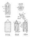
- Figures 15 and 16 show two embodiments of a hammer mass.
- the hammer mass 10D has a conical housing 44 flared trumpet in its upper part. In the lower part, the hammer mass ends in a conical bead 45 intended to improve the seal.
- the embodiment of the hammer mass 10E of FIG. 16 is close to the hammer mass 10D of FIG. 15 except that this hammer mass comprises longitudinal incipient fractures 46, which facilitate the opening of the hammer mass at the time of impact.
- FIGS. 17A and 17B show the grooved external shape of a hammer mass 10. These figures reveal the helical grooves 12, as well as, in the case of the cut of FIG. 17B, the incipient fractures 46.
- Figures 18 and 19 show other embodiments of a hammer mass.
- the hammer mass 10E of FIG. 18 further comprises helical grooves 12 also of sawtooth section rings 47 constituting attachment means.
- FIG. 19 differs from that of FIG. 18 in that it comprises, in its lower part, a conical sealing bead 45.
- Figure 20 is an enlarged view of a variant of the front part 8 and especially of the shoulder 16B relative to the embodiment of Figure 7 so as to retain the hammer mass 10 at impact to avoid that, sliding on the rod 9, it does not open and deviate over the shoulder 16B.
- the hammer mass 10 communicates its energy to the neutralizing part 8 and remains integral with the latter.
- FIG. 21 shows, in detail, the assembly in a single piece formed by the neutralizing part 8 and the rod 9 terminated by a pointed end 18.
- FIG. 22 shows an alternative embodiment of the part shown in FIG. 21.
- the neutralizing part 8C is constituted by the constriction of a tube, itself flattened to form a zone 48 then the rod 9B which is formed a filling 49, for example made of lead or an active mass and a sheath 50 of the sleeve used to make the parts 8C and 48.
- FIG. 23 shows a particular embodiment of ribs 51 in the form of a knife situated upstream from the shoulder 16 of the neutralizing part 8 in order to open the hammer mass 10 more easily and more effectively.
- FIG. 24 shows explicitly in section an embodiment already mentioned above in the different variants.
- This variant is similar to those of FIGS. 4.5 both for the sleeve 19 and for the internal element 51 formed from a more tapered head or front part 8 ′, with a bicorne section and a rear rod 9.
- the mass -hammer 10 ′ threaded on the rear rod 9 is in the form of a bottomless sleeve, the inside of the sleeve 19 being closed by a plug 119 to seal against the propellants coming against the bottom, from the outside, so as not to remove the sleeve 19.
- the bottom plug 119 can be hooked to the sleeve 19 by a mechanical connection (connection by shape) but also by gluing (thermofusion), depending on the nature of the material of the sleeve 19 and the plug 119.
- the hammer mass 10 ′ has a shape adapted to that of the stopper so as to properly rest on it when firing and to avoid cutting or perforating it.
- this hammer mass 10 ′ advances on the rod 9 it rises on the cone of the front part 8 ′ and begins to flare while cooperating with the internal surface, before conical 1119 of the sleeve 19 so as to slightly swell the sleeve and improve sealing.
- the hammer mass is of relatively small size which, made possible thanks to the invention, allows powder saving and therefore also less nuisance (noise) or greater comfort for the hunter (less violent impact on his shoulder).
- the external surface of the sleeve 19 may have more or less accentuated peripheral grooves receiving, if necessary, a lubricant.
- the sleeve 19 is completely closed and its part su is open to manufacturing; the internal element 5 with the hammer mass 10 ′ are introduced by the tip and then the front of the sleeve 19 is closed, for example by heat sealing or gluing.
- the sleeve 19 can be made in two abutted or nested parts and secured to one another.
Abstract
Description
L'invention concerne une munition pour armes à feu, notamment muniton de chasse.The invention relates to a munition for firearms, in particular hunting ammunition.
On connaît déjà de telles munitions.Such ammunition is already known.
Ainsi le brevet FR 75 04 418 concerne un projectile pour armes à feu formé d'une pièce métallique à deux diamètres différents avec des angles vifs, l'ensemble étant entouré par un enrobage en matière plastique. Le but de cette structure et notamment de l'enrobage en matière plastique est de donner au projectile une bonne pénétration dans l'air tout en lui permettant de passer le choke du canon. Ce projectile est muni d'une partie formant en quelque sorte une bourre qui assure l'étanchéité aux gaz à l'arrière du projectile lorsque celui-ci se trouve dans le canon. En outre les angles vifs de cette pièce surmoulée vieillissent mal à cause des contraintes.Thus patent FR 75 04 418 relates to a projectile for firearms formed of a metal part with two different diameters with sharp angles, the whole being surrounded by a coating of plastic material. The purpose of this structure and in particular of the plastic coating is to give the projectile good penetration in the air while allowing it to pass the choke from the barrel. This projectile is provided with a part which forms a sort of flock which ensures gas tightness at the rear of the projectile when the latter is in the barrel. In addition, the sharp angles of this molded part age badly because of the constraints.
Ce projectile présente un certain nombre d'inconvénients et, en particulier, une réalisation relativement compliquée ; sa stabilisation sur la trajectoire est défectueuse, ce qui en détériore la précision et enfin son pouvoir neutralisant est discutable.This projectile has a number of drawbacks and, in particular, a relatively complicated production; its stabilization on the trajectory is defective, which deteriorates its precision and finally its neutralizing power is questionable.
Le brevet FR 80 22 879 concerne un projecti le très voisin du type du projectile ci-dessus et dont la partie arrière est constituée par une pièce alvéolaire formant la "bourre". Ce projectile présente sensiblement les mêmes inconvénients que celui analysé ci-dessus.Patent FR 80 22 879 relates to a projecti very similar to the type of the above projectile and the rear part of which is constituted by a cellular part forming the "flock". This projectile has substantially the same drawbacks as that analyzed above.
Il existe également d'autres types de projectiles pour armes de chasse utilisant le principe de fléchettes comme, par exemple, celui décrit au brevet FR 75 39 022 ou au brevet EP 143 720.There are also other types of projectiles for hunting weapons using the dart principle such as, for example, that described in patent FR 75 39 022 or in patent EP 143 720.
Ces deux types de projectiles ont pour inconvénient d'être d'une structure très compliquée surtout au niveau de la fabrication et de la mise en place du projectile dans la douille et d'avoir un mauvais pouvoir neutralisant.These two types of projectiles have the drawback of being of a very complicated structure, especially at the level of the manufacture and of the positioning of the projectile in the shell and of having poor neutralizing power.
Les balles de type fléchette sont dangereuses pour l'environnement et la séparation des parties (du sabot) et de la fléchette risque de perturber la trajectoire.Dart balls are dangerous for the environment and the separation of the parts (of the hoof) and the dart may disturb the trajectory.
En résumé, les munitions de chasse, connues actuellement, telles que les balles BRENNEKE, BLONDEAU ou SAUVESTRE ne possèdent pas de pouvoir neutralisant élevé et, de plus, certaines munitions sont dangereuses pour l'environnement à cause des ricochets sur les obstacles (arbre, etc...) qu'ils peuvent trouver sur leur trajectoire.In summary, currently known hunting ammunition, such as the BRENNEKE, BLONDEAU or SAUVESTRE bullets, does not have a high neutralizing power and, moreover, certain ammunition is dangerous for the environment because of the ricochets on obstacles (tree, etc ...) that they can find on their trajectory.
Il existe également des munitions dits "de cimenterie" destinées à décoller l'anneau de ciment qui se forme à l'intérieur du four de cimenterie, ces munitions consistant simplement en un projectile lourd de forme quelconque qui est tiré à l'entrée du four en direction de l'anneau pour le fractionner.There are also so-called “cement” munitions intended to take off the cement ring which forms inside the cement kiln, these munitions consisting simply of a heavy projectile of any shape which is fired at the entrance to the kiln. toward the ring to split it.
La présente invention a pour but de remédier à ces inconvénients et se propose de créer une munition pour arme à feu, susceptible d'être tirée par tout type d'armes à feu, à canon rayé ou à canon lis se, et qui présente une excellente précision de tir et un haut pouvoir neutralisant, en particulier dans des objectifs mous, légers etc..The present invention aims to remedy these drawbacks and proposes to create an ammunition for a firearm, capable of being fired by any type of firearm, with rifled barrel or with cannon lis and which has excellent shooting accuracy and high neutralizing power, particularly in soft, light objectives, etc.
A cet effet, l'invention concerne une munition du type ci-dessus, caractérisé en ce que le projectile comprend :
- un élément interne,
- un élément externe,
- un moyen d'accrochage anti-recul de l'élément interne sur l'élément externe,
l'élément interne comprenant :
- une partie avant de forme neutralisante,
- une tige arrière reliée à cette partie avant,
- une masse-marteau emmanchée au moins en partie sur la tige arrière,
l'élément externe se composant :
- d'un habillage extérieur de forme aérodynamique recouvrant l'avant et les parois latérales de l'élément interne pour donner au projectile une bonne pénétration dans l'air et éviter l'usure du canon,
et le moyen d'accrochage anti-recul assure la liaison de l'élément interne et de l'élément externe pour qu'au moins, au démarrage, l'élément externe ne puisse avancer plus rapidement que l'élément interne.To this end, the invention relates to a munition of the above type, characterized in that the projectile comprises:
- an internal element,
- an external element,
a means of anti-retraction attachment of the internal element to the external element,
the internal element comprising:
- a neutralizing front part,
- a rear rod connected to this front part,
- a hammer mass fitted at least partially on the rear rod,
the external element consisting of:
- an aerodynamically shaped outer covering covering the front and the side walls of the internal element to give the projectile good penetration into the air and prevent wear of the barrel,
and the anti-recoil hooking means ensures the connection of the internal element and the external element so that at least, at start-up, the external element cannot advance faster than the internal element.
Cette munition utilisée soit comme munition de chasse, soit pour d'autres applications comme par exemple une munition pour cimenterie ou autres, présente un excellent pouvoir neutralisant et peut fonctionner comme projectile assemblé ou préassemblé avant son montage sur la cartouche. Du fait de l'élément externe, cette munition à projectile sous calibré peut être tirée par n'importe quel type d'armes à feu. Dans le cas d'une arme à canon rayé ou lisse, si le projectile est assemblé, c'est-à-dire si la masse-marteau est déjà emmanchée complètement sur la tige, il se conduit comme un projectile classique pour ce type d'arme. Par contre, si le projectile est seulement préassemblé, lors de la montée en pression, la masse-marteau s'emmanche sur la tige et se bloque sur cette tige et dans l'élément externe et du fait des rainures hélicoïdales il se met en rotation.This ammunition used either as hunting ammunition or for other applications such as for example a munition for cement works or the like, has excellent neutralizing power and can function as an assembled or preassembled projectile before it is mounted on the cartridge. Because of the external element, this calibrated projectile ammunition can be fired by any type of firearm. In the case of a weapon with a rifled or smooth barrel, if the projectile is assembled, that is to say if the hammer mass is already completely fitted on the rod, it will drove like a conventional projectile for this type of weapon. On the other hand, if the projectile is only pre-assembled, during the pressure build-up, the hammer mass is fitted on the rod and is blocked on this rod and in the external element and due to the helical grooves it starts to rotate .
Cette mise en rotation dans un canon lisse (arme de chasse) assure une stabilisation parfaite du projectile sur sa trajectoire et donne une excellente précision de tir.This rotation in a smooth barrel (hunting weapon) ensures perfect stabilization of the projectile on its trajectory and gives excellent shooting precision.
Le pouvoir neutralisant peut être à deux niveaux soit à l'impact du fait de la forme de l'élément interne du projectile soit tout de suite après l'impact dû au glissement de la masse-marteau sur la tige de l'élément interne. Le pouvoir neutralisant est particulièrement important lorsque cette munition est utilisée à la chasse car cela évite que la bête ne soit que blessée comme cela est fréquemment le cas avec les munitions actuelles en particulier des munitions de type "fléchette".The neutralizing power can be at two levels either at impact due to the shape of the internal element of the projectile or immediately after the impact due to the sliding of the hammer mass on the rod of the internal element. The neutralizing power is particularly important when this ammunition is used for hunting because it prevents the beast from being injured as is frequently the case with current ammunition in particular ammunition of the "dart" type.
Une telle munition peut également s'envisager pour le tir réduit, à l'entraînement, etc...Such ammunition can also be considered for reduced fire, training, etc ...
Suivant une autre caractéristique de l'invention, la munition comporte des moyens d'étanchéité entre, d'une part, l'élément interne et l'élément externe et, d'autre part, entre l'élément externe et le canon.According to another characteristic of the invention, the ammunition comprises sealing means between, on the one hand, the internal element and the external element and, on the other hand, between the external element and the barrel.
Ces moyens d'étanchéité assurent toute l'efficacité à la charge de propulsion en évitant par ailleurs que les différents éléments du projectile ne puissent se désolidariser sous l'effet des gaz.These sealing means ensure all the efficiency of the propellant charge while also preventing the various elements of the projectile from being able to separate under the effect of the gases.
Suivant une autre caractéristique l'élément externe est moins lourd que l'élément interne.According to another characteristic, the external element is lighter than the internal element.
Cette caractéristique est particulièrement intéressante pour la précision du tir à cause de la stabilisation du projectile sur sa trajectoire.This characteristic is particularly interesting for the accuracy of the shot because of the stabilization of the projectile on its trajectory.
Suivant une autre caractéristique, la partie avant neutralisante de l'élément interne est une pièce de révolution de forme sensiblement conique à génératrice non nécessairement droite et dont la base est large par rapport à la hauteur ; la partie avant neutralisante présente une cavité axiale ouverte vers l'avant.According to another characteristic, the neutralizing front part of the internal element is a part of revolution of substantially conical shape with a generator which is not necessarily straight and whose base is wide relative to the height; the neutralizing front part has an axial cavity open towards the front.
Il est en particulier intéressant que la tige arrière soit reliée à la partie avant de manière former un épaulement sur lequel peut venir buter la masse marteau au cours de son mouvement de translation relative.It is in particular interesting that the rear rod is connected to the front part so as to form a shoulder on which the hammer mass can abut during its relative translational movement.
Suivant une autre caractéristique, l'épaulement entre l'extrémité avant et la tige arrière se prolonge par une partie conique inversée.According to another characteristic, the shoulder between the front end and the rear rod is extended by an inverted conical part.
Cette partie conique inversée permet de faire passer la masse marteau par-dessus la partie neutralisante au moment de l'impact de la balle. Il est en particulier intéressant que la tige arrière comporte juste derrière l'épaulement formé avec l'extrémité avant, des nervures de cisaillement.This inverted conical part allows the hammer mass to pass over the neutralizing part at the moment of impact of the ball. It is in particular interesting that the rear rod comprises, just behind the shoulder formed with the front end, shear ribs.
De cette manière, la masse marteau augmente considérablement l'effet neutralisant du projectile.In this way, the hammer mass considerably increases the neutralizing effect of the projectile.
Suivant une autre caractéristique, la tige comporte des gorges annulaires servant de dégagements.According to another characteristic, the rod has annular grooves serving as clearances.
Ces gorges annulaires facilitent le coulissement de la masse marteau sur la tige.These annular grooves facilitate the sliding of the hammer mass on the rod.
Suivant une autre caractéristique la tige a une section conique dont le sommet est dirigé vers l'arrière de façon que, lors du mouvement d'avancement relatif de la masse-marteau par rapport à la tige, la forme conique de la tige agisse comme un coin.According to another characteristic, the rod has a conical section, the apex of which is directed towards the rear so that, during the relative forward movement of the hammer mass relative to the rod, the conical shape of the rod acts as a corner.
Suivant une autre caractéristique, l'extrémité arrière de la tige est pointue de manière à per forer la masse-marteau au moment de l'impact sur la cible.According to another characteristic, the rear end of the rod is pointed so as to per drill the hammer mass upon impact on the target.
Suivant une autre caractéristique, l'extrémité avant et la tige arrière sont réalisées sous la forme d'un manchon dont l'extrémité avant est rétreinte pour former une pointe se poursuivant par une partie écrasée constituant un bourrelet formant ainsi l'extrémité avant neutralisante, l'ensemble étant rempli d'une masse notamment du plomb ou une masse active.According to another characteristic, the front end and the rear rod are produced in the form of a sleeve the front end of which is constricted to form a point continuing with a crushed part constituting a bead thus forming the neutralizing front end, the assembly being filled with a mass, in particular lead or an active mass.
Cette forme de réalisation est particulièrement simple et intéressante sur le plan de la fabrication.This embodiment is particularly simple and interesting from the manufacturing point of view.
Suivant une autre caractéristique, la masse marteau est en forme de manchon dont la section correspond sensiblement à la section annulaire de l'intervalle entre la surface intérieure de l'élément externe et la surface de la tige arrière, ce manchon étant terminé à l'arrière par un bourrelet extérieur venant s'appuyer contre au moins une partie du fond de l'élément externe.According to another characteristic, the hammer mass is in the form of a sleeve, the section of which corresponds substantially to the annular section of the gap between the internal surface of the external element and the surface of the rear rod, this sleeve being finished at the rear by an external bead coming to bear against at least part of the bottom of the external element.
Suivant une autre caractéristique, le manchon formant la masse marteau présente des amorces longitudinales de rupture.According to another characteristic, the sleeve forming the hammer mass has longitudinal incipient fractures.
Suivant une autre caractéristique, la surface extérieure de la masse marteau est munie de nervures (rainures) hélicoïdales pour communiquer une impulsion de rotation à l'élément externe au départ du coup, élément externe qui est muni lui-même de rainures ou de nervures complémentaires.According to another characteristic, the external surface of the hammer mass is provided with helical ribs (grooves) to communicate a rotational impulse to the external element at the start of the blow, external element which is itself provided with complementary grooves or ribs .
Suivant une autre caractéristique, l'élément externe est en forme de manchon muni d'une partie avant recouvrant la partie avant neutralisante de l'élément interne de manière aérodynamique.According to another characteristic, the external element is in the form of a sleeve provided with a front part covering the neutralizing front part of the internal element aerodynamically.
Suivant une autre caractéristique, le man chon et la partie avant sont réalisés en une seule pièce.According to another characteristic, the man chon and the front part are made in one piece.
Suivant une autre caractéristique, le manchon présente une surface extérieure à nervures/rainures longitudinales hélicoïdales ou annulaires.According to another characteristic, the sleeve has an outer surface with helical or annular longitudinal ribs / grooves.
Suivant une autre caractéristique le moyen d'accrochage anti-recul entre l'élément interne et l'élément externe est constitué par des stries ou des nervures d'accrochage réalisées dans la surface extérieure du manchon de l'élément interne ou la surface intérieure de l'élément externe.According to another characteristic, the anti-recoil attachment means between the internal element and the external element consists of grooves or attachment ribs produced in the external surface of the sleeve of the internal element or the internal surface of the external element.
La présente invention sera décrite de manière plus détaillée à l'aide de divers exemples de réalisation représentés schématiquement par les dessins annexés, dans lesquels :
- - la figure 1 est une vue en coupe schématique d'ensemble d'une munition selon l'invention,
- - la figure 2 montre une variante de munition selon l'invention,
- - la figure 3 montre une autre variante de munition selon l'invention,
- - la figure 4 est une vue en coupe du projectile d'une munition selon l'invention, la masse-marteau étant en position de retrait (préassemblage).
- - la figure 5 est une coupe du projectile de la figure 4, la masse-marteau étant en position avancée,
- - la figure 6A est une coupe de l'élément interne du projectile après l'impact, selon une première possibilité,
- - la figure 6B montre l'élément interne du projectile après l'impact, selon une deuxième possibilité,
- - la figure 7 est une vue en coupe analogue à la figure 4, du projectile selon une seconde variante de l'invention,
- - la figure 8 est une vue en coupe analogue à la figu re 5 d'une troisième variante de l'invention,
- - la figure 9 est une vue en coupe analogue à la figure 5 montrant une quatrième variante de l'invention,
- - la figure 10A est une vue en coupe analogue à la figure 5 d'une cinquième variante de l'invention,
- - la figure 10B est une vue en coupe perpendiculaire à l'axe de la variante de la figure 10A,
- - la figure 11 est une vue de détail de la figure 10B,
- - la figure 12A est une vue en coupe d'une sixième variante de l'invention,
- - la figure 12B est une coupe perpendiculaire à l'axe de la variante de la figure 12A,
- - la figure 12C est une vue de côté du projectile selon la figure 12A,
- - les figures 13 et 14 sont des vues en coupe d'autres variantes du projectile selon l'invention,
- - la figure 15 est une vue en coupe axiale d'un mode de réalisation d'une masse-marteau,
- - la figure 16 est une vue en coupe axiale d'une variante de réalisation de la masse-marteau de la figure 15,
- - la figure 17A est une vue de côté d'une masse-marteau,
- - la figure 17B est une coupe perpendiculaire à l'axe de la masse-marteau de la figure 17A,
- - la figure 18 est une vue de face d'une variante de réalisation de masse-marteau montrant les moyens d'accrochage,
- - la figure 19 est une autre variante de réalisation d'une masse-marteau,
- - la figure 20 montre la zone avant de l'élément interne d'un projectile, à l'impact,
- - la figure 21 est une vue d'un mode de réalisation d'un élément interne de projectile,
- - la figure 22 est une vue en coupe d'une variante de réalisation d'un élément interne d'une munition se lon l'invention,
- - la figure 23 montre une autre variante d'élément interne selon l'invention, montrant l'ouverture de la masse-marteau à l'impact.
- - la figure 24 est une vue en coupe d'un autre mode de réalisation d'un projectile selon l'invention.
- FIG. 1 is a diagrammatic sectional view of an assembly according to the invention,
- FIG. 2 shows a variant of ammunition according to the invention,
- FIG. 3 shows another variant of ammunition according to the invention,
- - Figure 4 is a sectional view of the projectile of a munition according to the invention, the hammer mass being in the withdrawn position (pre-assembly).
- FIG. 5 is a section of the projectile of FIG. 4, the hammer mass being in the advanced position,
- FIG. 6A is a section through the internal element of the projectile after impact, according to a first possibility,
- FIG. 6B shows the internal element of the projectile after impact, according to a second possibility,
- FIG. 7 is a sectional view similar to FIG. 4, of the projectile according to a second variant of the invention,
- - Figure 8 is a sectional view similar to the figure re 5 of a third variant of the invention,
- FIG. 9 is a sectional view similar to FIG. 5 showing a fourth variant of the invention,
- FIG. 10A is a sectional view similar to FIG. 5 of a fifth variant of the invention,
- FIG. 10B is a sectional view perpendicular to the axis of the variant of FIG. 10A,
- FIG. 11 is a detailed view of FIG. 10B,
- FIG. 12A is a sectional view of a sixth variant of the invention,
- FIG. 12B is a section perpendicular to the axis of the variant of FIG. 12A,
- FIG. 12C is a side view of the projectile according to FIG. 12A,
- FIGS. 13 and 14 are sectional views of other variants of the projectile according to the invention,
- FIG. 15 is a view in axial section of an embodiment of a hammer mass,
- FIG. 16 is a view in axial section of an alternative embodiment of the hammer mass of FIG. 15,
- FIG. 17A is a side view of a hammer mass,
- FIG. 17B is a section perpendicular to the axis of the hammer mass of FIG. 17A,
- FIG. 18 is a front view of an alternative embodiment of a hammer mass showing the attachment means,
- FIG. 19 is another alternative embodiment of a hammer mass,
- FIG. 20 shows the front zone of the internal element of a projectile, on impact,
- FIG. 21 is a view of an embodiment of an internal projectile element,
- - Figure 22 is a sectional view of an alternative embodiment of an internal element of a munition is according to the invention,
- - Figure 23 shows another variant of internal element according to the invention, showing the opening of the hammer mass on impact.
- - Figure 24 is a sectional view of another embodiment of a projectile according to the invention.
Selon la figure 1, l'invention concerne une munition composée d'une douille 1 contenant la charge propulsive 2 avec l'amorce 3 et un projectile 4, sous-calibré. Cette munition est destinée à une arme à feu à canon lisse.According to Figure 1, the invention relates to an ammunition composed of a cartridge 1 containing the
Les figures 2 et 3 montrent deux autres variantes de cartouche à douille 1A, 1B et amorces 3A, 3B, avec une charge 2A, 2B et un projectile 4A, 4B.Figures 2 and 3 show two other variants of
Selon la figure 4, le projectile représenté en coupe se compose d'un élément interne 5 et d'un élément externe 6 ainsi que d'un moyen d'accrochage antirecul 7 entre l'élément interne 5 et l'élément externe 6.According to FIG. 4, the projectile shown in section consists of an
L'élément interne 5 comprend une partie avant 8 de forme neutralisante et une tige arrière 9 reliée à la partie avant 8. L'élément interne 5 comprend également une masse-marteau 10 emmanchée, en partie au moins, sur la tige arrière 9. Il subsiste ainsi un intervalle 11A entre la partie avant 8 et l'extrémité avant de la masse-marteau 10 permettant, au départ du coup, à la masse-marteau d'avancer sur la tige 9 et de communiquer au projectile une impulsion de rotation comme cela sera expliqué ci-après.The
L'avance de la masse-marteau au départ du coup est progressive et amortit l'effet de recul de l'arme. De plus, il y a également un intervalle 11B derrière le manchon 19, devant la charge de poudre ; l'air emprisonné dans ces deux intervalles 11A, 11B sert de coussin amortisseur.The advance of the hammer mass at the start of the shot is progressive and dampens the recoil effect of the weapon. In addition, there is also a
La masse-marteau 10 comporte des nervures ou rainures hélicoïdales 12 dont une seule est représentée à la figure 4 de manière que son mouvement de translation ou d'emmanchement sur la tige 9 au départ du coup, provoque, par effet de vissage, une mise en rotation de l'élément externe 6.The
L'élément externe 6 se compose d'un habillage extérieur dont, notamment, la partie avant 13 est enveloppante, de manière à recouvrir l'avant et les parois latérales de l'élément interne 5 pour donner au projectile une forme aérodynamique lui assurant une bonne pénétration dans l'air.The
Le moyen d'accrochage anti-recul 7 assure, de manière générale, la liaison de l'élément interne 5 et de l'élément externe 6, de façon qu'au départ du coup, l'élément externe 6 ne puisse se déchausser de l'élément interne sous l'effet des forces appliquées par la pression des gaz de propulsion de la chambre de l'arme à feu. Ces moyens d'accrochage permettent, toutefois, au moins lorsque la disposition de la masse-marteau est celle de la figure 4, de continuer à s'emmancher sur la tige 9 pour communiquer l'impulsion de rotation à l'élément externe 6 et, par suite, à l'ensemble du projectile.The anti-recoil hooking means 7 generally ensures the connection of the
L'extrémité inférieure de la masse-marteau comprend un bourrelet tronconique 14 destiné à venir se loger dans une partie en dépouille 15, de forme sensiblement correspondante, à l'entrée du logement non référencé défini par l'élément externe 6 et qui reçoit l'élément interne 5. Ce bourrelet annulaire 14 constitue un moyen d'étanchéité évitant, au départ du coup, une fois la masse-marteau emmanchée complètement sur la tige 9, aux gaz de pénétrer dans l'intervalle entre l'élément interne 5 et l'élément externe 6 en risquant de déchausser l'élément externe 6. Des moyens d'étanchéité sont également prévus pour le contact de l'élément externe 6 contre la surface du canon. Ces moyens seront détaillés ultérieurement.The lower end of the hammer mass comprises a
La partie avant neutralisante 8 de l'élément interne 5 est, de préférence, une pièce de révolution de forme sensiblement conique. La génératrice de ce cône n'est pas nécessairement une droite et peut être avantageusement constituée par une ligne courbe, un cône à surface ''concave" par exemple en forme d'arc de cercle ou autre, pour assurer une meilleure pénétration du projectile dans la cible avec un effet neutralisant. Il est à remarquer que pour favoriser cet effet neutralisant, le cône est très écrasé, c'est-à-dire que l'angle au sommet est très ouvert, la base du cône étant large par rapport à la hauteur.The neutralizing
La tige 9 est reliée à la partie avant 8 pour former un épaulement 16 important contre lequel vient buter la masse-marteau 10 au cours de son mouvement de translation sur la tige 9. Cette venue en butée ou en contact n'a pas été représentée de manière intentionnelle à la figure 4. Au départ du coup, la masse-marteau 10 peut également s'arrêterdans son mouvement sur la tige 9, à une certaine distance de l'épaulement 16, la venue en butée ne se faisant qu'au moment de l'impact. Après ce premier mouvement, la masse-marteau peut rester bloquée ou poursuivre son mouvement.The
Selon le mode de réalisation des figures 4 et 5, l'épaulement 16 est précédé par une forme de révolution, en cône inversé 17.According to the embodiment of FIGS. 4 and 5, the
Suivant une autre variante décrite ultérieurement, derrière l'épaulement 16, la forme conique 17 est remplacée ou complétée par des nervures de cisaillement qui, au moment de l'impact, assurent l'ouverture de la masse-marteau comme une tulipe.According to another variant described later, behind the
Selon le dessin schématique de la figure 1, la tige 9 a une section conique dont le sommet est dirigé vers l'arrière de sorte que lors de l'avancée de la masse-marteau 10 sur la tige 9, la forme conique de la tige 9 crée un effet de coin écartant la masse-marteau et assurant, par suite, l'écartement et le blocage de l'élément externe 6 sur l'élément interne 5.According to the schematic drawing of FIG. 1, the
Selon la figure 2, l'extrémité arrière 18 de la tige 9 est en forme de pointe, de manière à perforer le fond de la masse-marteau au moment de l'impact du projectile sur la cible, pour faciliter l'effet de pénétration et de neutralisation de la masse-marteau 10 dans la cible.According to FIG. 2, the
Il est à remarquer comme cela sera décrit ultérieurement que la masse-marteau 10 se présente sous la forme d'un manchon dont la section correspond sensiblement à la section annulaire de l'intervalle entre la surface intérieure de l'élément externe 6 et la surface extérieure de la tige arrière 9. L'adaptation des dimensions est plus ou moins accentuée pour créer un effet de serrage qui devient progressif du fait de la conicité relative de la forme de la masse-marteau et de la forme de la tige 9 ainsi que de l'effet de dilatation diamétrale créée par les moyens d'accrochage anti-recul 7 entre l'élément interne 5 et l'élément externe 6. L'élément externe 6 subit également un léger gonflement qui compense l'usure du canon.It should be noted as will be described later that the
Selon la figure 4, le manchon 19 qui constitue le volume cylindrique de l'élément externe 6 est muni de nervures ou de rainures ou cannelures 20, 21 qui, dans cet exemple, sont de forme annulaire pour réduire le frottement entre l'élément externe 6 du projectile et la surface du canon de l'arme à feu.According to Figure 4, the
Le logement intérieur formé par le manchon 19 est souvent de forme cylindrique mais dans certains cas, pour améliorer la tenue entre la masse marteau 10 et l'élément externe 6 (manchon 19) au départ du coup il peut être intéressant de réaliser ce logement avec une forme en contre-dépouille, (c'est-à-dire évasée vers l'avant).The interior housing formed by the
Dans la suite de la description on envisagera d'autres moyens pour réaliser ou augmenter la tenue, voire l'accrochage entre la masse-marteau 10 et le manchon 19 (ou élément externe 6).In the following description, other means will be considered to achieve or increase the holding, or even the attachment, between the
La figure 5 montre la position de l'élément interne 5 et en particulier de la masse-marteau 10, enfoncé dans l'élément externe 6 telle que se présente la disposition de ces différentes parties dans le projectile au moins après le départ du coup.FIG. 5 shows the position of the
En effet, selon l'invention et pour des raisons d'utilisation, il peut être intéressant de monter le projectile dans la cartouche soit dans la position représentée à la figure 4, c'est-à-dire avec la masse-marteau 10 en retrait par rapport à l'élément externe 6, soit avec la masse-marteau 10 déjà enfoncée comme représentée à la figure 5.Indeed, according to the invention and for reasons of use, it may be advantageous to mount the projectile in the cartridge either in the position shown in Figure 4, that is to say with the
La figure 6A montre l'état de l'élément interne 5 du projectile au moment de son impact sur la cible non représentée. A ce moment, l'élément externe est retenu contre la surface de la cible où il pénètre légèrement alors que l'élément interne pénètre dans la cible pour la neutraliser. Au moment où la partie avant 8 rencontre la cible, et sous l'effet de la décélération subie par l'élément (8, 9) la masse-marteau 10 continue d'avancer sous l'effet de son énergie cinétique et s'ouvre en passant par dessus l'épaulement 16 de la partie 8. Cette ouverture peut être favorisée, comme cela sera vu ultérieurement, par des nervures qui découpent la masse-marteau 10 en lamelles, de sorte que celle-ci s'ouvre à la manière d'une tulipe et accentue l'effet neutralisant du projectile.FIG. 6A shows the state of the
L'extrémité 18 de la tige 9 favorise le mouvement d'avancée de la masse-marteau par rapport à la tige 9 puisque cette extrémité facilite la perforation du fond de la masse-marteau et la déforme comme cela est représenté schématiquement à la figure 6A.The
La figure 6B montre une variante de situation résultant de la forme différente de l'épaulement 16A, qui comporte une gorge tournée vers l'arrière dans laquelle s'encastre la masse-marteau 10 au moment de l'impact lorsqu'elle tente d'avancer sous l'effet de son énergie par rapport à la tige 9. Dans ce cas, elle ne dépasse pas la partie avant 8, mais accentue l'énergie de celle-ci. De la sorte, la masse-marteau 10 se tasse comme cela est indiqué schématiquement aux dessins.FIG. 6B shows a variant of the situation resulting from the different shape of the
La figure 7 montre une seconde variante de réalisation de la munition selon l'invention. Cette variante fait figurer une partie de la douille 1 dont l'extrémité supérieure 22 est rabattue sur l'épaulement 23 formé entre la partie supérieure 13 et le manchon 19 de la partie externe 6. Cette figure montre la disposition des moyens d'étanchéité en forme de lèvre 24 prévus à la base du manchon 19 et s'appuyant contre la surface extérieure de la masse-marteau 10 pour recouvrir celle-ci une fois qu'elle est enfoncée sur la tige 9. Cette figure montre également des gorges formant dégagements 25, 26 annulaires, réalisées dans la tige 9 pour faciliter le glissement de la masse-marteau 10 sur la tige 9.Figure 7 shows a second alternative embodiment of the munition according to the invention. This variant includes a part of the sleeve 1, the
Enfin, sur le bord extérieur du manchon 19, au niveau du fond, est prévu un moyen d'étanchéité en forme de lèvre 27 qui est appliqué contre la douille 1 mais qui, une fois que le projectile a pénétré dans le canon, assure l'étanchéité par rapport à la paroi du canon pour éviter les pertes de gaz et la mise en flottement du projectile.Finally, on the outer edge of the
La figure 8 montre une troisième variante de projectile de munition selon l'invention. Cette variante se distingue des précédents modes de réalisation par les lèvres 28 en partie haute du manchon 19 de l'élément externe 6 ainsi que de la gorge annulaire 29 réalisée dans le fond du manchon 19 et qui délimite une lèvre extérieure 30 pour l'étanchéité entre l'élément externe 6 et le canon ainsi qu'une lèvre intérieure 31 assurant l'étanchéité entre le manchon et la masse-marteau 10. On remarquera la forme particulière des lèvres 30 et 31 qui présentent des surfaces importantes soumises à la pression des gaz et assurent, de ce fait, une parfaite étanchéité.Figure 8 shows a third variant of ammunition projectile according to the invention. This variant differs from previous embodiments by the lips 28 in the upper part of the
Cette figure montre également un mode de réalisation particulier du moyen d'accrochage antirecul 7A. Il s'agit d'un profil en dents de scie réalisé soit dans la masse-marteau 10, soit dans la surface intérieure de l'élément 6 ou dans les deux surfaces. D'ailleurs, il n'est pas indispensable que les formes des moyens d'accrochage se correspondent exactement.This figure also shows a particular embodiment of the anti-kickback attachment means 7A. It is a sawtooth profile produced either in the
Suivant une variante non représentée, la surface intérieure du manchon 19 comporte des lèvres anti-recul.According to a variant not shown, the inner surface of the
La figure 9 montre une autre variante de réalisation du projectile de munition selon l'invention. Cette variante se distingue par une forme différente du manchon 19A et un abaissement de la position de l'épaulement 23A servant au sertissage du projectile dans la douille (non représentée). En partie inférieure, le manchon 19A est muni d'une lèvre d'étanchéité 32 périphérique. La surface extérieure du man chon 19A présente des ondulations 33 ayant les mêmes fonctions que les ondulations des modes de réalisation ci-dessus.Figure 9 shows another alternative embodiment of the ammunition projectile according to the invention. This variant is distinguished by a different shape of the
La tige 9 est munie, au niveau de sa liaison avec l'épaulement 16 de la partie avant 8 de plusieurs nervures 34 de cisaillage destinées à cisailler la masse-marteau 10 à l'impact lorsqu'elle tente de glisser par dessus l'épaulement 16 sous l'effet de son énergie.The
Cette figure montre également une forme particulière 7B de réalisation du moyen d'accrochage anti-recul; ce moyen d'accrochage 7B est en forme d'un ou de plusieurs filets de vis.This figure also shows a particular embodiment 7B of the anti-recoil attachment means; this attachment means 7B is in the form of one or more screw threads.
Enfin, la partie avant 13A de l'élément extérieur est en forme d'ogive et son extrémité avant présente une cavité 35 destinée à faciliter sa perforation par la partie avant 8 du projectile au moment de l'impact. Un voile 36 de faible épaisseur ferme le fond de la cavité 35 pour éviter la pénétration d'humidité à l'intérieur du projectile.Finally, the
Les figures 10A, 10B montrent une autre variante de réalisation. Cette variante se distingue des précédentes par la forme de la partie avant 8A qui comporte une cavité 37, et par la forme de la partie avant 13B de l'élément extérieur 6 qui présente également une cavité 38 prolongeant la cavité 37. La masse-marteau 10 est munie de bourrelets périphériques 7C formant des moyens d'accrochage anti-recul. Enfin, la surface extérieure du manchon 19B est munie de nervures longitudinales 39 et de nervures ou plots transversaux 40 destinés à réduire la surface de contact entre le manchon 19B de l'élément extérieur et la surface du canon.Figures 10A, 10B show another alternative embodiment. This variant differs from the previous ones by the shape of the
La figure 10B et l'agrandissement partiel de la figure 11 laissent apparaître les filets 41A, 41B assurant la mise en rotation. Les filets mâle/femelle peuvent avoir des sections diverses (rectangulaires, carrée, trapézoïdale, symétrique ou asymétrique) pour favoriser l'entraînement en rotation par un accrochage parfait entre les deux pièces.FIG. 10B and the partial enlargement of FIG. 11 reveal the
Les figures 12A et 12B montrent une sixième me variante de réalisation de l'invention. Cette variante se distingue des précédentes principalement par la forme de la surface extérieure du manchon 19C ainsi que par la présence d'amorces de cisaillement 42 réalisées dans la masse-marteau 10 (comme cela sera explicité ultérieurement).Figures 12A and 12B show a sixth alternative embodiment of the invention. This variant differs from the previous ones mainly by the shape of the outer surface of the
La figure 12C est une vue de côté du projectile des figures 12A et 12BFigure 12C is a side view of the projectile of Figures 12A and 12B
La figure 13 montre une autre variante de réalisation. Dans cette figure, l'élément extérieur 6 est en deux parties, une coiffe 13C et un manchon 16C solidarisés l'un à l'autre. Par ailleurs, la masse-marteau 10A est directement solidaire de la partie avant 8A.Figure 13 shows another alternative embodiment. In this figure, the
La variante représentée à la figure 14 est légèrement différente par la forme de la masse-marteau 10B qui présente, à l'avant, une partie évasée 43 facilitant son passage par dessus la pointe en forme de flèche 8B constituant la partie neutralisante. Enfin, la partie externe 6 se compose d'un premier manchon 16D et d'une chemise 16E. Par ailleurs, le fond 10C de la masse-marteau s'appuie contre le fond de l'élément externe 6 pour éviter toute désolidarisation au moment du coup.The variant shown in FIG. 14 is slightly different by the shape of the hammer mass 10B which has, at the front, a flared
Il est à remarquer qu'aux différentes figures 8, 9, 10A, 12A, 13, et 14, la masse-marteau est déjà enfoncée dans l'élément externe (assemblage). Il s'agit comme déjà précisé plus haut soit d'une situation intentionnelle réalisée lors de la fabrication de la cartouche, soit, ce qui est plus général, de la position relative des différentes pièces du projectile après le départ du coup et mise en rotation de celui-ci.It should be noted that in the different figures 8, 9, 10A, 12A, 13, and 14, the hammer mass is already pressed into the external element (assembly). This is, as already specified above, either an intentional situation realized during the manufacture of the cartridge, or, which is more general, the relative position of the different parts of the projectile after the start of the shot and its rotation.
Les figures 15 et 16 montrent deux modes de réalisation d'une masse-marteau. Selon la figure 15, la masse-marteau 10D présente un logement conique 44 évasé en trompette dans sa partie supérieure. En partie inférieure, la masse-marteau se termine par un bourrelet conique 45 destiné à améliorer l'étanchéité.Figures 15 and 16 show two embodiments of a hammer mass. According to Figure 15, the
Le mode de réalisation de la masse-marteau 10E de la figure 16 est voisin de la masse-marteau 10D de la figure 15 sauf que cette masse-marteau comporte des amorces de rupture 46 longitudinales, qui facilitent l'ouverture de la masse-marteau au moment de l'impact.The embodiment of the
Les figures 17A et 17B montrent la forme extérieure rainurée d'une masse-marteau 10. Ces figures laissent apparaître les rainures hélicoïdales 12, ainsi que dans le cas de la coupe de la figure 17B, les amorces de rupture 46.FIGS. 17A and 17B show the grooved external shape of a
Les figures 18 et 19 montrent d'autres modes de réalisation d'une masse-marteau. La masse-marteau 10E de la figure 18 comporte, en plus, des rainures hélicoïdales 12 également des anneaux à section en dents de scie 47 constituant des moyens d'accrochage.Figures 18 and 19 show other embodiments of a hammer mass. The
La variante de la figure 19 se distingue de celle de la figure 18 en ce qu'elle comporte, en sa partie inférieure, un bourrelet conique d'étanchéité 45.The variant of FIG. 19 differs from that of FIG. 18 in that it comprises, in its lower part, a
La figure 20 est une vue agrandie d'une variante de la partie avant 8 et surtout de l'épaulement 16B par rapport au mode de réalisation de la figure 7 de manière à retenir la masse-marteau 10 au moment de l'impact pour éviter que, glissant sur la tige 9, elle ne s'ouvre et ne s'écarte par-dessus l'épaulement 16B. Dans ce cas, comme dans celui de la figure 7, la masse-marteau 10 communique son énergie à la partie neutralisante 8 et reste solidaire de celle-ci.Figure 20 is an enlarged view of a variant of the
La figure 21 montre, de manière détaillée, l'ensemble en une seule pièce formé de la partie neutralisante 8 et de la tige 9 terminée par une extrémité en pointe 18.FIG. 21 shows, in detail, the assembly in a single piece formed by the neutralizing
La figure 22 montre une variante de réalisation de la pièce représentée à la figure 21. Dans cette variante la partie neutralisante 8C est constituée par le rétreint d'un tube, lui-même aplati pour former une zone 48 puis la tige 9B qui est formée d'un remplissage 49, par exemple en plomb ou d'une masse active et d'une gaine 50 du manchon ayant servi à faire les parties 8C et 48.FIG. 22 shows an alternative embodiment of the part shown in FIG. 21. In this alternative, the neutralizing
La figure 23 montre un mode de réalisation particulier de nervures 51 en forme de couteau situées en amont de l'épaulement 16 de la partie neutralisante 8 pour ouvrir plus facilement et plus efficacement la masse-marteau 10.FIG. 23 shows a particular embodiment of
La figure 24 montre en coupe de manière explicite un mode de réalisation déjà évoqué ci-dessus dans les différentes variantes. Cette variante est voisine de celles des figures 4,5 tant pour le manchon 19 que pour l'élément interne 51 formé d'une tête ou partie avant 8′ plus effilée, à section en bicorne et d'une tige arrière 9. La masse-marteau 10′ enfilée sur la tige arrière 9 est en forme de manchon sans fond, l'intérieur du manchon 19 étant fermé par un bouchon 119 pour assurer l'étanchéité vis-à-vis des gaz de propulsion venant s'appliquer contre le fond, par l'extérieur, de manière à ne pas faire déchausser le manchon 19. Le bouchon de fond 119 peut être accroché au manchon 19 par une liaison mécanique (liaison par la forme) mais aussi par collage (thermofusion), suivant la nature du matériau du manchon 19 et du bouchon 119.FIG. 24 shows explicitly in section an embodiment already mentioned above in the different variants. This variant is similar to those of FIGS. 4.5 both for the
La masse-marteau 10′ a une forme adaptée à celle du bouchon de manière à bien prendre appui sur celui-ci au moment du tir et d'éviter de le découper ou perforer. Lorsque cette masse-marteau 10′ avance sur la tige 9 elle monte sur le cône de la partie avant 8′ et commence à s'évaser tout en coopérant avec la surface intérieure, avant conique 1119 du manchon 19 de manière à faire gonfler légèrement le manchon et améliorer l'étanchéité.The
Il est à remarquer que dans ce mode de réalisation, la masse-marteau est de dimension relativement réduite ce qui, rendu possible grâce à l'invention, permet une économie de poudre et par suite également moins de nuisances (bruit) ou un plus grand confort pour le chasseur (choc moins violent sur son épaule).It should be noted that in this embodiment, the hammer mass is of relatively small size which, made possible thanks to the invention, allows powder saving and therefore also less nuisance (noise) or greater comfort for the hunter (less violent impact on his shoulder).
Lorsque la masse-marteau 10′ est en position avancée, près du cône de la partie 8′, le centre de gravité du projectile est décalé vers l'avant ce qui augmente considérablement la stabilité sur la trajectoire et par suite la précision du tir.When the
Suivant une variante non représentée on peut améliorer l'étanchéité du manchon dans le canon par une lèvre prévue à la base du manchon et en regard de cette lèvre une surface annulaire à section en forme d'arc de parabole dont le ''foyer" est situé sur la lèvre.According to a variant not shown, it is possible to improve the sealing of the sleeve in the barrel by a lip provided at the base of the sleeve and opposite this lip an annular surface with a cross section in the shape of a parabola arc whose "focus" is located on the lip.
Suivant une autre caractéristique, la surface extérieure du manchon 19 peut avoir des rainures périphériques plus ou moins accentuées recevant le cas échéant un lubrifiant.According to another characteristic, the external surface of the
Enfin, suivant une autre variante non représentée le manchon 19 est à fond fermé et sa partie su périeure est ouverte à la fabrication ; l'élément interne 5 avec la masse-marteau 10′ s'introduisent par la pointe puis on ferme l'avant du manchon 19 par exemple par thermosoudage ou collage. D'ailleurs le manchon 19 peut être réalisé en deux parties aboutées ou emboîtées et solidarisées l'une à l'autre.Finally, according to another variant not shown, the
Claims (21)
- un élément interne (5),
- un élément externe (6),
- un moyen d'accrochage anti-recul (7) de l'élément interne (5) sur l'élément externe (6),
l'élément interne (5) comprenant :
- une partie avant (8) de forme neutralisante,
- une tige arrière (9) reliée à cette partie avant,
- une masse-marteau (10) emmanchée au moins en partie sur la tige arrière 9,
l'élément externe (6) se composant :
- d'un habillage extérieur (19, 13) de forme aérodynamique recouvrant l'avant et les parois latérales de l'élément interne (5) pour donner au projectile une bonne pénétration dans l'air,
et le moyen d'accrochage anti-recul (7) assure la liaison de l'élément interne (5) et de l'élément externe (6) pour qu'au moins, au démarrage, l'élément externe ne puisse avancer plus rapidement que l'élément interne.1) Ammunition composed of a casing containing the propellant charge and a sub-calibrated projectile for a firearm, ammunition characterized in that the projectile comprises:
- an internal element (5),
- an external element (6),
an anti-recoil attachment means (7) of the internal element (5) on the external element (6),
the internal element (5) comprising:
- a front part (8) of neutralizing form,
- a rear rod (9) connected to this front part,
a hammer mass (10) fitted at least in part on the rear rod 9,
the external element (6) consisting of:
- an outer casing (19, 13) of aerodynamic shape covering the front and the side walls of the internal element (5) to give the projectile good penetration into the air,
and the anti-recoil hooking means (7) ensures the connection of the internal element (5) and the external element (6) so that at least, at startup, the external element cannot advance more quickly as the internal element.
Priority Applications (1)
| Application Number | Priority Date | Filing Date | Title |
|---|---|---|---|
| AT89400554T ATE89072T1 (en) | 1988-02-29 | 1989-02-28 | AMMUNITION FOR FIREARMS, IN PARTICULAR SHOTGUN AMMUNITION. |
Applications Claiming Priority (3)
| Application Number | Priority Date | Filing Date | Title |
|---|---|---|---|
| FR8802475A FR2627854B1 (en) | 1988-02-29 | 1988-02-29 | AMMUNITION FOR FIREARMS, IN PARTICULAR HUNTING AMMUNITION |
| FR8802475 | 1988-02-29 | ||
| CA000609605A CA1333544C (en) | 1988-02-29 | 1989-08-28 | Firearm ammunition, namely for hunting |
Publications (2)
| Publication Number | Publication Date |
|---|---|
| EP0333542A1 true EP0333542A1 (en) | 1989-09-20 |
| EP0333542B1 EP0333542B1 (en) | 1993-05-05 |
Family
ID=25672985
Family Applications (1)
| Application Number | Title | Priority Date | Filing Date |
|---|---|---|---|
| EP89400554A Expired - Lifetime EP0333542B1 (en) | 1988-02-29 | 1989-02-28 | Ammunition for firearms, especially shotgun ammunition |
Country Status (8)
| Country | Link |
|---|---|
| US (1) | US4977834A (en) |
| EP (1) | EP0333542B1 (en) |
| AT (1) | ATE89072T1 (en) |
| AU (1) | AU608998B1 (en) |
| CA (1) | CA1333544C (en) |
| DE (1) | DE68906298T2 (en) |
| ES (1) | ES2042017T3 (en) |
| FR (1) | FR2627854B1 (en) |
Cited By (5)
| Publication number | Priority date | Publication date | Assignee | Title |
|---|---|---|---|---|
| FR2724450A1 (en) * | 1994-09-13 | 1996-03-15 | Sauvestre Jean Claude | DOUBLE PENETRATION HUNTING BALL WITH REDUCED RANGE |
| WO1996008708A1 (en) * | 1994-09-13 | 1996-03-21 | Mobil Oil Corporation | Method for monitoring grease consistency |
| FR2726357A1 (en) * | 1994-10-26 | 1996-05-03 | Sauvestre Jean Claude | TELESCOPED BOOM HUNTING BALL, COMPRISING A SUB-PROJECTILE ASSOCIATED WITH A LAUNCHER |
| FR2880680A1 (en) * | 2005-01-10 | 2006-07-14 | Jean Pierre Denis | Training and action round for rifle or handgun has supple plastic case with high-density plastic core and optional metal dart |
| WO2009056082A1 (en) * | 2007-11-02 | 2009-05-07 | Jallcom Holdings Ltd. | Ammunition for shooting from a smooth barrel |
Families Citing this family (22)
| Publication number | Priority date | Publication date | Assignee | Title |
|---|---|---|---|---|
| CA1333543C (en) * | 1987-10-05 | 1994-12-20 | Jean-Pierre Denis | Firearm projectile |
| US5149913A (en) * | 1990-09-05 | 1992-09-22 | Arakaki Steven Y | Forced expanding bullet |
| FR2673278B1 (en) * | 1991-02-26 | 1993-12-31 | Giat Industries | FRAGMENTABLE PERFORATING SUB-CALIBER PROJECTILE. |
| US5185495A (en) * | 1992-04-13 | 1993-02-09 | Petrovich Robert M | Projective with improved flowering |
| DE19754330C1 (en) * | 1997-11-22 | 1999-04-08 | Wilhelm Brenneke Gmbh & Co Kg | Subcaliber bullet especially for a gun with a rifled barrel |
| FR2795170B1 (en) * | 1999-06-18 | 2002-06-28 | Jean Claude Sauvestre | BALL WITH INTERNAL ARROW |
| JP3313097B2 (en) * | 1999-11-10 | 2002-08-12 | 永山電子工業株式会社 | Metal fastening members and shell exterior members |
| FR2817337B1 (en) * | 2000-11-24 | 2004-06-18 | Jean Pierre Denis | AMMUNITION COMPRISING A PROJECTILE IN THE FORM OF AN ARROW, A HAMMER AND AN ENVELOPE RECEIVING THIS SET |
| US6679178B2 (en) * | 2000-12-21 | 2004-01-20 | Gueorgui M. Mihaylov | Smooth bore barrel system with self spinning ammunition |
| WO2002086414A1 (en) * | 2001-04-19 | 2002-10-31 | Ruag Ammotec Gmbh | Bullet for infantry ammunition |
| US7827915B1 (en) * | 2001-09-27 | 2010-11-09 | Accura Bullets | Gas check with system for improved loading and retention in bore of muzzleloading firearms |
| US20110048272A1 (en) * | 2001-09-27 | 2011-03-03 | Hall Daniel W | Gas check with system for improved loading and retention in bore of muzzleloading firearms |
| US7444942B2 (en) * | 2005-12-23 | 2008-11-04 | Accura Bullets, Llc | Saboted projectile with external ridges and/or internal locking edge for muzzleloading firearms |
| US7096791B2 (en) * | 2002-07-12 | 2006-08-29 | Arthur Vanmoor | Projectile with improved dynamic shape |
| DE10244571C1 (en) * | 2002-09-25 | 2003-12-04 | Wilhelm Brenneke Gmbh & Co Kg | Shotgun or smooth bore projectile, has hollow front section connected by location of intentional breakage to rear section which slides into it during firing |
| US7681504B2 (en) * | 2003-08-26 | 2010-03-23 | Bae Systems Information And Electronic Systems Integration Inc. | Method and apparatus for displacing material and projectile thereof |
| PT1676092T (en) * | 2003-10-11 | 2016-10-17 | Ruag Ammotec Gmbh | Slug cartridge for a shotgun with intermediate means and cartridge |
| FR2863046B1 (en) * | 2003-11-25 | 2006-08-11 | Jean Pierre Denis | AMMUNITION |
| FR2867267B1 (en) * | 2004-03-08 | 2006-05-26 | Jean Claude Sauvestre | HUNTING BALL WITH EXPANSION RING |
| KR100843573B1 (en) * | 2008-03-13 | 2008-07-03 | (주)한국원자력 엔지니어링 | Ammunition |
| WO2013141929A2 (en) * | 2011-12-28 | 2013-09-26 | Fritz Randy R | Hollow bullet with internal structure |
| US11867487B1 (en) | 2021-03-03 | 2024-01-09 | Wach Llc | System and method for aeronautical stabilization |
Citations (4)
| Publication number | Priority date | Publication date | Assignee | Title |
|---|---|---|---|---|
| US2493938A (en) * | 1946-12-09 | 1950-01-10 | Albree George Norman | Ammunition |
| FR1457971A (en) * | 1964-12-12 | 1966-11-04 | Dynamit Nobel Ag | Jacketed projectile for hunting cartridges |
| DE1578119A1 (en) * | 1967-06-06 | 1970-08-27 | Dynamit Nobel Ag | Shotgun barrel |
| DE2929628A1 (en) * | 1979-07-21 | 1981-02-12 | Brenneke Wilhelm Kg | Hunting gun cartridge - has free space between pot and piston shaped parts of elastic wad |
Family Cites Families (12)
| Publication number | Priority date | Publication date | Assignee | Title |
|---|---|---|---|---|
| US904255A (en) * | 1907-12-07 | 1908-11-17 | Emil Gathmann | Projectile. |
| US3318244A (en) * | 1965-07-01 | 1967-05-09 | Charles E Rostocil | Cartridge |
| US3398682A (en) * | 1966-09-14 | 1968-08-27 | Michael F. Abela | Spinning projectile |
| FR2300319A1 (en) * | 1975-02-07 | 1976-09-03 | Cleard Gilbert | Shot gun cartridge with plastics sleeve - has grooved longitudinally metal part with conical nose and hollow wad at rear |
| FR2335818A1 (en) * | 1975-12-19 | 1977-07-15 | Le Neillon Richard | High power, high precision finned projectile for hunting weapon - guided within barrel by expanded polystyrene sabots |
| IT1196905B (en) * | 1979-10-26 | 1988-11-25 | Snia Viscosa | SMOOTH BARREL HUNTED SHOTGUNS |
| US4413564A (en) * | 1981-05-01 | 1983-11-08 | Brown Worthy H | Slug for a shotgun shell |
| FR2513369A1 (en) * | 1981-09-24 | 1983-03-25 | Robert Antoine | PROJECTILES FOR HAND AND RAY SHAPED HAND AND SHOULDER GUNS AT VERY HIGH INITIAL SPEEDS, IN ACCORDANCE WITH THE HAGUE CONVENTIONS AND PRODUCING THE SAME NEUTRALIZING EFFECTS AS SHALLOWED OR EXPLOSIVE PROJECTILES. CLAIM: TWO DEVICES, USE. |
| DE3241149C2 (en) * | 1982-11-08 | 1984-12-20 | Wilhelm Brenneke Kg Fabrikation Von Jagdgeschossen, 3012 Langenhagen | Shotgun barrel |
| PT77697B (en) * | 1982-11-24 | 1986-02-12 | Ladriere Serge | IMPROVED PROJECTILE FOR DISCHARGE BY FIREARMS |
| AU5626286A (en) * | 1985-03-27 | 1986-10-23 | Scientific Cartridge Developments Ltd. | Shotgun cartridge |
| AU5359086A (en) * | 1986-01-23 | 1987-08-14 | Johnson, P.I. | Shotgun slug cartridge |
-
1988
- 1988-02-29 FR FR8802475A patent/FR2627854B1/en not_active Expired - Lifetime
-
1989
- 1989-02-28 DE DE89400554T patent/DE68906298T2/en not_active Expired - Fee Related
- 1989-02-28 ES ES198989400554T patent/ES2042017T3/en not_active Expired - Lifetime
- 1989-02-28 EP EP89400554A patent/EP0333542B1/en not_active Expired - Lifetime
- 1989-02-28 AT AT89400554T patent/ATE89072T1/en not_active IP Right Cessation
- 1989-08-28 CA CA000609605A patent/CA1333544C/en not_active Expired - Fee Related
- 1989-08-28 US US07/399,193 patent/US4977834A/en not_active Expired - Lifetime
- 1989-08-29 AU AU40874/89A patent/AU608998B1/en not_active Ceased
Patent Citations (4)
| Publication number | Priority date | Publication date | Assignee | Title |
|---|---|---|---|---|
| US2493938A (en) * | 1946-12-09 | 1950-01-10 | Albree George Norman | Ammunition |
| FR1457971A (en) * | 1964-12-12 | 1966-11-04 | Dynamit Nobel Ag | Jacketed projectile for hunting cartridges |
| DE1578119A1 (en) * | 1967-06-06 | 1970-08-27 | Dynamit Nobel Ag | Shotgun barrel |
| DE2929628A1 (en) * | 1979-07-21 | 1981-02-12 | Brenneke Wilhelm Kg | Hunting gun cartridge - has free space between pot and piston shaped parts of elastic wad |
Cited By (9)
| Publication number | Priority date | Publication date | Assignee | Title |
|---|---|---|---|---|
| FR2724450A1 (en) * | 1994-09-13 | 1996-03-15 | Sauvestre Jean Claude | DOUBLE PENETRATION HUNTING BALL WITH REDUCED RANGE |
| WO1996008689A1 (en) * | 1994-09-13 | 1996-03-21 | Sauvestre Jean Claude | Close range dual penetration bullet for hunting |
| WO1996008708A1 (en) * | 1994-09-13 | 1996-03-21 | Mobil Oil Corporation | Method for monitoring grease consistency |
| US5723810A (en) * | 1994-09-13 | 1998-03-03 | Sauvestre; Jean-Claude | Double-penetration reduced-range hunting bullet |
| FR2726357A1 (en) * | 1994-10-26 | 1996-05-03 | Sauvestre Jean Claude | TELESCOPED BOOM HUNTING BALL, COMPRISING A SUB-PROJECTILE ASSOCIATED WITH A LAUNCHER |
| WO1996013697A1 (en) * | 1994-10-26 | 1996-05-09 | Sauvestre Jean Claude | Telescoping arrow-type hunting bullet with a sub-projectile combined with a launching element |
| US5804759A (en) * | 1994-10-26 | 1998-09-08 | Sauvestre; Jean-Claude | Hunting bullet having a telescoping flechette and comprising a sub-projectile connected to a launcher |
| FR2880680A1 (en) * | 2005-01-10 | 2006-07-14 | Jean Pierre Denis | Training and action round for rifle or handgun has supple plastic case with high-density plastic core and optional metal dart |
| WO2009056082A1 (en) * | 2007-11-02 | 2009-05-07 | Jallcom Holdings Ltd. | Ammunition for shooting from a smooth barrel |
Also Published As
| Publication number | Publication date |
|---|---|
| FR2627854B1 (en) | 1990-08-10 |
| DE68906298T2 (en) | 1993-12-02 |
| DE68906298D1 (en) | 1993-06-09 |
| FR2627854A1 (en) | 1989-09-01 |
| AU608998B1 (en) | 1991-04-18 |
| CA1333544C (en) | 1994-12-20 |
| EP0333542B1 (en) | 1993-05-05 |
| ES2042017T3 (en) | 1993-12-01 |
| US4977834A (en) | 1990-12-18 |
| ATE89072T1 (en) | 1993-05-15 |
Similar Documents
| Publication | Publication Date | Title |
|---|---|---|
| EP0333542B1 (en) | Ammunition for firearms, especially shotgun ammunition | |
| CA1333543C (en) | Firearm projectile | |
| CA2558031C (en) | Hunting bullet comprising an expansion ring | |
| EP1188032B1 (en) | Bullet with an internally carried sub-projectile | |
| EP2691731B1 (en) | Less lethal weapon projectile | |
| EP2297545B1 (en) | Non-lethal munition | |
| FR2529319A1 (en) | AMMUNITION COMPRISING A PROPULSIVE LOAD AND A FINISH STABILIZED PROJECTILE | |
| EP0106263B1 (en) | Armour perforating explosive projectile within a cartridge case | |
| EP0572643B1 (en) | Bullet fragment retaining socket tube for rifle grenades | |
| EP0737298B1 (en) | Telescoping arrow-type hunting bullet with a sub-projectile combined with a launching element | |
| EP0728293B1 (en) | Close range dual penetration bullet for hunting | |
| WO1991002211A1 (en) | Improvements in munitions intended to be fired from a smooth-bored weapon | |
| FR2719373A1 (en) | Propulsion unit for riot control grenade | |
| EP0310723A1 (en) | Bullet for a gun | |
| CA1337544C (en) | Projectile to be fired by a firearm | |
| EP0382657A1 (en) | Cartridge for a rifle and other firearms | |
| EP1023573B1 (en) | Launcher with enhanced tightness for ammunitions comprising a launcher associated with a sub-projectile | |
| FR2950688A1 (en) | Projectile for reduced lethal weapon, has core provided with rear end and front end, where rear end is assembled with front wall of cup, and external envelope covering front end of core | |
| FR2538892A1 (en) | Practice projectile for mortar fire and its fuse | |
| BE708180A (en) | ||
| FR2732456A1 (en) | Seal ring for shoe of dart projectile, e.g. anti-tank weapon |
Legal Events
| Date | Code | Title | Description |
|---|---|---|---|
| PUAI | Public reference made under article 153(3) epc to a published international application that has entered the european phase |
Free format text: ORIGINAL CODE: 0009012 |
|
| AK | Designated contracting states |
Kind code of ref document: A1 Designated state(s): AT BE CH DE ES GB GR IT LI LU NL SE |
|
| 17P | Request for examination filed |
Effective date: 19900308 |
|
| 17Q | First examination report despatched |
Effective date: 19910808 |
|
| GRAA | (expected) grant |
Free format text: ORIGINAL CODE: 0009210 |
|
| AK | Designated contracting states |
Kind code of ref document: B1 Designated state(s): AT BE CH DE ES GB GR IT LI LU NL SE |
|
| PG25 | Lapsed in a contracting state [announced via postgrant information from national office to epo] |
Ref country code: SE Effective date: 19930505 Ref country code: NL Effective date: 19930505 Ref country code: AT Effective date: 19930505 |
|
| REF | Corresponds to: |
Ref document number: 89072 Country of ref document: AT Date of ref document: 19930515 Kind code of ref document: T |
|
| REF | Corresponds to: |
Ref document number: 68906298 Country of ref document: DE Date of ref document: 19930609 |
|
| ITF | It: translation for a ep patent filed |
Owner name: STUDIO TORTA SOCIETA' SEMPLICE |
|
| GBT | Gb: translation of ep patent filed (gb section 77(6)(a)/1977) |
Effective date: 19930811 |
|
| NLV1 | Nl: lapsed or annulled due to failure to fulfill the requirements of art. 29p and 29m of the patents act | ||
| REG | Reference to a national code |
Ref country code: GR Ref legal event code: FG4A Free format text: 3008687 |
|
| REG | Reference to a national code |
Ref country code: ES Ref legal event code: FG2A Ref document number: 2042017 Country of ref document: ES Kind code of ref document: T3 |
|
| PG25 | Lapsed in a contracting state [announced via postgrant information from national office to epo] |
Ref country code: LU Free format text: LAPSE BECAUSE OF NON-PAYMENT OF DUE FEES Effective date: 19940228 Ref country code: LI Effective date: 19940228 Ref country code: CH Effective date: 19940228 |
|
| PLBE | No opposition filed within time limit |
Free format text: ORIGINAL CODE: 0009261 |
|
| STAA | Information on the status of an ep patent application or granted ep patent |
Free format text: STATUS: NO OPPOSITION FILED WITHIN TIME LIMIT |
|
| 26N | No opposition filed | ||
| REG | Reference to a national code |
Ref country code: CH Ref legal event code: PL |
|
| REG | Reference to a national code |
Ref country code: CH Ref legal event code: AUV Free format text: LE BREVET CI-DESSUS EST TOMBE EN DECHEANCE, FAUTE DE PAIEMENT, DE LA 6E ANNUITE. |
|
| REG | Reference to a national code |
Ref country code: GB Ref legal event code: IF02 |
|
| PGFP | Annual fee paid to national office [announced via postgrant information from national office to epo] |
Ref country code: GR Payment date: 20040227 Year of fee payment: 16 |
|
| PG25 | Lapsed in a contracting state [announced via postgrant information from national office to epo] |
Ref country code: GR Free format text: LAPSE BECAUSE OF NON-PAYMENT OF DUE FEES Effective date: 20050905 |
|
| PGFP | Annual fee paid to national office [announced via postgrant information from national office to epo] |
Ref country code: GB Payment date: 20070227 Year of fee payment: 19 |
|
| PGFP | Annual fee paid to national office [announced via postgrant information from national office to epo] |
Ref country code: ES Payment date: 20070228 Year of fee payment: 19 |
|
| PGFP | Annual fee paid to national office [announced via postgrant information from national office to epo] |
Ref country code: BE Payment date: 20070305 Year of fee payment: 19 |
|
| PGFP | Annual fee paid to national office [announced via postgrant information from national office to epo] |
Ref country code: DE Payment date: 20070327 Year of fee payment: 19 |
|
| PGFP | Annual fee paid to national office [announced via postgrant information from national office to epo] |
Ref country code: IT Payment date: 20070517 Year of fee payment: 19 |
|
| BERE | Be: lapsed |
Owner name: *DENIS JEAN-PIERRE Effective date: 20080228 |
|
| GBPC | Gb: european patent ceased through non-payment of renewal fee |
Effective date: 20080228 |
|
| PG25 | Lapsed in a contracting state [announced via postgrant information from national office to epo] |
Ref country code: DE Free format text: LAPSE BECAUSE OF NON-PAYMENT OF DUE FEES Effective date: 20080902 |
|
| PG25 | Lapsed in a contracting state [announced via postgrant information from national office to epo] |
Ref country code: BE Free format text: LAPSE BECAUSE OF NON-PAYMENT OF DUE FEES Effective date: 20080228 |
|
| REG | Reference to a national code |
Ref country code: ES Ref legal event code: FD2A Effective date: 20080229 |
|
| PG25 | Lapsed in a contracting state [announced via postgrant information from national office to epo] |
Ref country code: GB Free format text: LAPSE BECAUSE OF NON-PAYMENT OF DUE FEES Effective date: 20080228 |
|
| PG25 | Lapsed in a contracting state [announced via postgrant information from national office to epo] |
Ref country code: ES Free format text: LAPSE BECAUSE OF NON-PAYMENT OF DUE FEES Effective date: 20080229 |
|
| PG25 | Lapsed in a contracting state [announced via postgrant information from national office to epo] |
Ref country code: IT Free format text: LAPSE BECAUSE OF NON-PAYMENT OF DUE FEES Effective date: 20080228 |