EP0333512A2 - Vorrichtung zur Unterstützung einer optischen Linse in einem optischen Kopf - Google Patents
Vorrichtung zur Unterstützung einer optischen Linse in einem optischen Kopf Download PDFInfo
- Publication number
- EP0333512A2 EP0333512A2 EP89302674A EP89302674A EP0333512A2 EP 0333512 A2 EP0333512 A2 EP 0333512A2 EP 89302674 A EP89302674 A EP 89302674A EP 89302674 A EP89302674 A EP 89302674A EP 0333512 A2 EP0333512 A2 EP 0333512A2
- Authority
- EP
- European Patent Office
- Prior art keywords
- lens
- link mechanism
- optical axis
- supporting device
- holding
- Prior art date
- Legal status (The legal status is an assumption and is not a legal conclusion. Google has not performed a legal analysis and makes no representation as to the accuracy of the status listed.)
- Granted
Links
Images


Classifications
-
- G—PHYSICS
- G11—INFORMATION STORAGE
- G11B—INFORMATION STORAGE BASED ON RELATIVE MOVEMENT BETWEEN RECORD CARRIER AND TRANSDUCER
- G11B7/00—Recording or reproducing by optical means, e.g. recording using a thermal beam of optical radiation by modifying optical properties or the physical structure, reproducing using an optical beam at lower power by sensing optical properties; Record carriers therefor
- G11B7/08—Disposition or mounting of heads or light sources relatively to record carriers
- G11B7/09—Disposition or mounting of heads or light sources relatively to record carriers with provision for moving the light beam or focus plane for the purpose of maintaining alignment of the light beam relative to the record carrier during transducing operation, e.g. to compensate for surface irregularities of the latter or for track following
- G11B7/0925—Electromechanical actuators for lens positioning
- G11B7/0932—Details of sprung supports
-
- G—PHYSICS
- G11—INFORMATION STORAGE
- G11B—INFORMATION STORAGE BASED ON RELATIVE MOVEMENT BETWEEN RECORD CARRIER AND TRANSDUCER
- G11B7/00—Recording or reproducing by optical means, e.g. recording using a thermal beam of optical radiation by modifying optical properties or the physical structure, reproducing using an optical beam at lower power by sensing optical properties; Record carriers therefor
- G11B7/08—Disposition or mounting of heads or light sources relatively to record carriers
- G11B7/09—Disposition or mounting of heads or light sources relatively to record carriers with provision for moving the light beam or focus plane for the purpose of maintaining alignment of the light beam relative to the record carrier during transducing operation, e.g. to compensate for surface irregularities of the latter or for track following
- G11B7/0925—Electromechanical actuators for lens positioning
- G11B7/093—Electromechanical actuators for lens positioning for focusing and tracking
-
- G—PHYSICS
- G11—INFORMATION STORAGE
- G11B—INFORMATION STORAGE BASED ON RELATIVE MOVEMENT BETWEEN RECORD CARRIER AND TRANSDUCER
- G11B7/00—Recording or reproducing by optical means, e.g. recording using a thermal beam of optical radiation by modifying optical properties or the physical structure, reproducing using an optical beam at lower power by sensing optical properties; Record carriers therefor
- G11B7/12—Heads, e.g. forming of the optical beam spot or modulation of the optical beam
- G11B7/123—Integrated head arrangements, e.g. with source and detectors mounted on the same substrate
Definitions
- This invention relates to an optical head employed in an optical information recording/reproducing apparatus such as an optical disk player, and more particularly, to an improvement in a device for supporting an object lens.
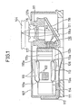
- Fig. 1 is a longitudinal sectional view of an optical head disclosed in the Japanese Patent Laying-Open No. 283430/1987
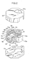
- Fig. 2 is an exploded perspective view of the optical head shown in Fig. 1.
- a yoke member 112 formed from a sheet material is attached to a base 11.
- a link member 113 cast in a mold is attached via pins 114 to the yoke member 112.
- a holding member 117 holding an object lens 115 and a semiconductor device 116 is attached to the forward end of the link member 113.
- a lid 118 having an opening 118a is attached to the holding member 117.
- a mirror 121 is attached to the lid 118 for closing the opening 118a.
- the semiconductor device 116 includes a semiconductor laser for emitting a laser beam 143 and a photosensor for sensing the laser beam reflected from a disk 144.
- the link member 113 includes hinges 113a for swinging the holding member 117 along the direction of the optical axis of the object lens 115, as indicated by chain dotted lines in Fig. 1, for effecting focusing adjustment, and also includes a hinge 113b for swinging the holding member 117 along the direction normal to the optical axis of the object lens 115, for effecting tracking adjustment.
- a counterbalance 122 is provided to the holding member 117 at a portion opposite to the object lens 115 with respect to the hinge 113b.
- the yoke member 112 is provided with upstanding plate sections 112a, 112b, formed by bending, and a magnet 123 is mounted to a surface of the upstanding plate section 112a confronting to the upstanding plate section 112b.
- a focusing coil 124 is attached to the holding member 117 for surrounding the upstanding plate section 112b.
- a tracking coil 125 is attached to the focusing coil 124 for confronting to the magnet 123.
- the semiconductor device 116, focusing coil 124 and the tracking coil 125 are connected electrically to the outside through a flexible wiring board or substrate 126.
- the hinge member 113 and the holding member 117 are covered by a cap 127 having an opening 127a at a position above the object lens 115.
- the link member 113, hinge 113b and object lens 115 are arrayed along a straight line in this sequence without overlapping.
- the object lens supporting device has a longer length, resulting in a larger size of the overall optical head.
- the counterbalance 122 need be inserted in the link mechanism to complete the object lens supporting device, after the formation of the link mechanism including the link member 113 and the hinge 113a, thus complicating the manufacture process for the object lens supporting device.
- an object lens supporting device wherein an object lens may be displaced within an optical head in both the direction along the optical axis of the lens and the direction normal to the optical axis, comprises a link mechanism having substantially the form of a parallelepiped and making it possible to displace the lens in the direction along the optical axis, the link mechanism comprising four plates and first hinge means including four hinges interconnecting the four plates, a rotatable member rotatable within the parallelepiped, second hinge means connecting said rotatable member to the inner wall of one of the four plates to make it possible to rotate the rotatable member about an axis parallel to the optical axis, lens holding means supported by the rotatable member and adapted for holding the object lens, and a base for stationarily holding another of the plates facing to said one plate holding the second hinge means.
- an object lens supporting device wherein an object lens may be displaced within an optical head in both the direction along the optical axis of the lens and the direction normal to the optical axis, comprises a link mechanism having substantially the form of a parallelepiped and making it possible to displace the lens in the direction along the optical axis, the link mechanism comprising four plates and first hinge means including four hinges interconnecting the four plates, a supporting member which is provided in the parallelepiped for supporting the link mechanism, second hinge means connecting the inner wall of one of the four plates to the supporting member to make it possible to rotate the link mechanism about an axis parallel to the optical axis, lens holding means supported by another of the plates facing to said one plate connected to said second hinge means, the lens holding means being adapted for holding the object lens, and a base for stationarily holding the supporting member.
- the object lens may be displaced along the optical axis by the link mechanism, and also is a direction normal to the optical axis by the second hinge means.
- the second hinge means is accommodated in the link mechanism, so that the lens supporting device is more compact in size than the conventional device.
- an object lens 1 is fixed to a lens supporting member 2.
- the lens supporting member 2 is substantially ring-shaped, and a counterbalance 4 is affixed to the side of the member 2 opposite to the object lens 1 with respect to an opening 3.
- a link mechanism 5 is inserted into the opening 3.
- the both ends of a rotatable plate 16 connected to the link mechanism 5 are inserted and fixed in a pair of slots 6 formed on the inner wall of the opening 3, whereby the lens supporting member 2 is supported by the link mechanism 5.
- Focusing coils 7 and tracking coils 8 are attached to the lens supporting member 2 and are connected to an external circuit through a flexible print board or substrate 9.
- the link mechanism 5 is molded from a soft synthetic region material.
- Four link plates 10, 11, 12 and 13 are arranged in the form of a parallelepiped and interconnected by four hinges 14a, 14b, 14c and 14d of a first hinge group having a first rotatable axis.
- a rotatable plate 16 is connected to the inner lateral side of the link plate 10 by a hinge 15 of a second hinge group having a second rotatable axis parallel to the surface of the link plate 10 and normal to the first axis of the first group hinges 14a to 14d.
- the rotatable plate 16 has its both ends inserted and fixed in the pair of slots 6 formed in the lens supporting member 2.
- the link plate 12 facing to the link plate 10 is provided with a through-hole 18 and pins 19 for engaging with the base 17.
- the base 17 has a pin 20 and holes 21 for engaging with the hole 18 and the pin 19 of the link plate 12, respectively.
- the link mechanism 5 is securely held on the base 17 through the intermediary of these engaging means 18-21.
- the base 17 is also provided with yokes 22a, 22b and magnets 23 constituting magnetic circuits in cooperation with the focusing coils 7 and the tracking coils 8.
- the parallelepipedic link mechanism 5 constituted by the link plates 10 to 15 and the first group hinges 14a to 14d, can be displaced as indicated by chain dotted lines.
- the link plate 10 can be moved up and down as indicated by an arrow mark A with respect to the link plate 12 secured to the base 17, whereby the object lens 4 can be displaced along the optical axis, as indicated by an arrow mark Y in Fig. 3, together with the lens supporting member 2.
- the rotatable plate 16 can be rotatively displaced, with the second group hinge 15 as center, as indicated by chain dotted lines and by an arrow mark B in Fig. 5.
- the object lens 1 can be rotated along with the lens supporting member 2 about the second group hinge 15 as center, this displacement being that in the tracking direction as indicated by an arrow mark X in Fig. 3.
- the object lens 1 can be displaced in both the focusing direction X and the tracking direction Y, and the focusing and tracking can be controlled appropriately under the driving force of magnetic circuits constituted by the coils 7, 8, yokes 22a, 22b and magnets 23.
- the lens supporting device may be made more compact than the conventional device.
- the counterbalance 4 can be attached to the lens supporting member 2 in a process step which is separate from the step of securing the link mechanism 5 to the base 17. It is also possible to have the counterbalance 4 formed simultaneously with the lens supporting member 2.
- the ring-shaped lens supporting member 2 has a mechanical strength higher than that of the conventional lens supporting member.
- the link plate 12 of the link mechanism 5 is secured to the base 17 and the rotatable plate 16 holds the lens supporting member 2.
- the link plate 12 may hold the lens supporting member 2 and the rotatable plate 16 may be secured to the base 17.
Landscapes
- Physics & Mathematics (AREA)
- Optics & Photonics (AREA)
- Optical Recording Or Reproduction (AREA)
Applications Claiming Priority (2)
| Application Number | Priority Date | Filing Date | Title |
|---|---|---|---|
| JP36014/88 | 1988-03-17 | ||
| JP1988036014U JP2529876Y2 (ja) | 1988-03-17 | 1988-03-17 | 対物レンズ支持装置 |
Publications (3)
| Publication Number | Publication Date |
|---|---|
| EP0333512A2 true EP0333512A2 (de) | 1989-09-20 |
| EP0333512A3 EP0333512A3 (en) | 1990-11-28 |
| EP0333512B1 EP0333512B1 (de) | 1994-01-19 |
Family
ID=12457894
Family Applications (1)
| Application Number | Title | Priority Date | Filing Date |
|---|---|---|---|
| EP89302674A Expired - Lifetime EP0333512B1 (de) | 1988-03-17 | 1989-03-17 | Vorrichtung zur Unterstützung einer optischen Linse in einem optischen Kopf |
Country Status (5)
| Country | Link |
|---|---|
| US (1) | US4969715A (de) |
| EP (1) | EP0333512B1 (de) |
| JP (1) | JP2529876Y2 (de) |
| KR (1) | KR910009103B1 (de) |
| DE (1) | DE68912370T2 (de) |
Cited By (2)
| Publication number | Priority date | Publication date | Assignee | Title |
|---|---|---|---|---|
| EP0343979A3 (de) * | 1988-05-25 | 1991-01-09 | Sharp Kabushiki Kaisha | Objektivlinsenantriebsgerät |
| EP0468613B1 (de) * | 1990-07-19 | 1997-07-09 | Pioneer Electronic Corporation | Optischer Plattenspieler |
Families Citing this family (5)
| Publication number | Priority date | Publication date | Assignee | Title |
|---|---|---|---|---|
| KR0153766B1 (ko) * | 1988-12-20 | 1998-12-15 | 이우에 사또시 | 광픽업장치 |
| US5293363A (en) * | 1989-10-13 | 1994-03-08 | Mitsubishi Denki Kabushiki Kaisha | Optical head apparatus with light weight movable lens holder |
| US5416640A (en) * | 1989-11-24 | 1995-05-16 | Matsushita Electric Industrial Co., Ltd. | Objective actuator |
| JPH0521325U (ja) * | 1991-08-13 | 1993-03-19 | 旭光学工業株式会社 | 光学式情報記録再生装置 |
| JPH0954969A (ja) * | 1995-08-11 | 1997-02-25 | Minebea Co Ltd | 対物レンズ支持装置 |
Family Cites Families (8)
| Publication number | Priority date | Publication date | Assignee | Title |
|---|---|---|---|---|
| JPS5920438U (ja) * | 1982-07-27 | 1984-02-07 | パイオニア株式会社 | 光学式情報読取装置における光学系駆動装置 |
| JPS60160032A (ja) * | 1984-01-30 | 1985-08-21 | Canon Inc | 光学的記録再生装置の対物レンズ駆動装置 |
| JPS60209935A (ja) * | 1984-03-31 | 1985-10-22 | Toshiba Corp | 光学ヘツド装置 |
| JPH0668843B2 (ja) * | 1985-08-16 | 1994-08-31 | ソニー株式会社 | 光学ピツクアツプ装置 |
| US4813033A (en) * | 1985-10-30 | 1989-03-14 | International Business Machines Corporation | Two axis electromagnetic actuator with axis balanced suspension |
| WO1987005142A1 (fr) * | 1986-02-24 | 1987-08-27 | Sony Corporation | Dispositif de detection de foyer |
| JPS62283430A (ja) * | 1986-05-31 | 1987-12-09 | Sony Corp | 光学ヘツド |
| JPH0750526B2 (ja) * | 1986-03-15 | 1995-05-31 | ソニー株式会社 | デイスクプレ−ヤの光学ヘツド装置 |
-
1988
- 1988-03-17 JP JP1988036014U patent/JP2529876Y2/ja not_active Expired - Lifetime
-
1989
- 1989-03-13 KR KR1019890003040A patent/KR910009103B1/ko not_active Expired
- 1989-03-17 EP EP89302674A patent/EP0333512B1/de not_active Expired - Lifetime
- 1989-03-17 US US07/324,687 patent/US4969715A/en not_active Expired - Lifetime
- 1989-03-17 DE DE68912370T patent/DE68912370T2/de not_active Expired - Fee Related
Cited By (2)
| Publication number | Priority date | Publication date | Assignee | Title |
|---|---|---|---|---|
| EP0343979A3 (de) * | 1988-05-25 | 1991-01-09 | Sharp Kabushiki Kaisha | Objektivlinsenantriebsgerät |
| EP0468613B1 (de) * | 1990-07-19 | 1997-07-09 | Pioneer Electronic Corporation | Optischer Plattenspieler |
Also Published As
| Publication number | Publication date |
|---|---|
| EP0333512B1 (de) | 1994-01-19 |
| KR910009103B1 (ko) | 1991-10-28 |
| DE68912370D1 (de) | 1994-03-03 |
| KR890015214A (ko) | 1989-10-28 |
| EP0333512A3 (en) | 1990-11-28 |
| JP2529876Y2 (ja) | 1997-03-19 |
| DE68912370T2 (de) | 1994-09-08 |
| JPH01140621U (de) | 1989-09-26 |
| US4969715A (en) | 1990-11-13 |
Similar Documents
| Publication | Publication Date | Title |
|---|---|---|
| US5541899A (en) | Optical pickup device with movable objective lens and stationary focusing and tracking coils | |
| US5313332A (en) | Flexure suspension for two axis actuator | |
| CA1323696C (en) | Object lens driving device | |
| US5073883A (en) | Objective lens driving apparatus including parallalogram structure | |
| US4811320A (en) | Optical type pickup apparatus with lens holder supported by frame wires each having an end inserted into a frame hole | |
| EP0440196B1 (de) | Haltevorrichtung für Linsenantriebssystem | |
| EP0394032B1 (de) | Optischer Kopf | |
| EP0376531B1 (de) | Steuerungsgerät für Objektivlinse | |
| US5313334A (en) | Objective lens moving actuator | |
| EP0735526B1 (de) | Optisches Abtastgerät | |
| US6594223B2 (en) | Lens driving apparatus for disk player having a lens holder supported by a plurality of elastic members having different spring constants | |
| EP0333512B1 (de) | Vorrichtung zur Unterstützung einer optischen Linse in einem optischen Kopf | |
| EP0238224B1 (de) | Optische Kopfeinrichtungen für Plattenspieler | |
| EP0617417A2 (de) | Gerät zum Antreiben einer Objektivlinse | |
| US5414563A (en) | Electromagnetic objective lens driving apparatus of optical data recording and reproducing apparatus | |
| US5586104A (en) | Apparatus for elevating a position determination pin and a spindle assembly for disc player | |
| KR100207626B1 (ko) | 렌즈구동장치 | |
| KR100266048B1 (ko) | 대물렌즈이동액츄에이터 | |
| KR19980083599A (ko) | 광픽업장치의 일체형 엑츄에이터 | |
| JPH01192023A (ja) | 対物レンズ駆動装置 | |
| KR0150964B1 (ko) | 대물렌즈 구동부 지지장치 | |
| JP3095056B2 (ja) | 対物レンズ駆動装置 | |
| JPH07153097A (ja) | 対物レンズ駆動装置 | |
| JPH01236434A (ja) | 対物レンズアクチュエータ | |
| JPS63177323A (ja) | 対物レンズ駆動装置 |
Legal Events
| Date | Code | Title | Description |
|---|---|---|---|
| PUAI | Public reference made under article 153(3) epc to a published international application that has entered the european phase |
Free format text: ORIGINAL CODE: 0009012 |
|
| AK | Designated contracting states |
Kind code of ref document: A2 Designated state(s): DE GB |
|
| PUAL | Search report despatched |
Free format text: ORIGINAL CODE: 0009013 |
|
| AK | Designated contracting states |
Kind code of ref document: A3 Designated state(s): DE GB |
|
| 17P | Request for examination filed |
Effective date: 19901214 |
|
| 17Q | First examination report despatched |
Effective date: 19920805 |
|
| GRAA | (expected) grant |
Free format text: ORIGINAL CODE: 0009210 |
|
| AK | Designated contracting states |
Kind code of ref document: B1 Designated state(s): DE GB |
|
| REF | Corresponds to: |
Ref document number: 68912370 Country of ref document: DE Date of ref document: 19940303 |
|
| PLBE | No opposition filed within time limit |
Free format text: ORIGINAL CODE: 0009261 |
|
| STAA | Information on the status of an ep patent application or granted ep patent |
Free format text: STATUS: NO OPPOSITION FILED WITHIN TIME LIMIT |
|
| 26N | No opposition filed | ||
| REG | Reference to a national code |
Ref country code: GB Ref legal event code: IF02 |
|
| PGFP | Annual fee paid to national office [announced via postgrant information from national office to epo] |
Ref country code: DE Payment date: 20050310 Year of fee payment: 17 |
|
| PGFP | Annual fee paid to national office [announced via postgrant information from national office to epo] |
Ref country code: GB Payment date: 20050316 Year of fee payment: 17 |
|
| PG25 | Lapsed in a contracting state [announced via postgrant information from national office to epo] |
Ref country code: GB Free format text: LAPSE BECAUSE OF NON-PAYMENT OF DUE FEES Effective date: 20060317 |
|
| PG25 | Lapsed in a contracting state [announced via postgrant information from national office to epo] |
Ref country code: DE Free format text: LAPSE BECAUSE OF NON-PAYMENT OF DUE FEES Effective date: 20061003 |
|
| GBPC | Gb: european patent ceased through non-payment of renewal fee |
Effective date: 20060317 |