EP0332500A1 - Fahrzeug für Unterhaltsarbeiten an Oberflächen von Unterwasserteilen von schwimmenden Strukturen - Google Patents
Fahrzeug für Unterhaltsarbeiten an Oberflächen von Unterwasserteilen von schwimmenden Strukturen Download PDFInfo
- Publication number
- EP0332500A1 EP0332500A1 EP89400552A EP89400552A EP0332500A1 EP 0332500 A1 EP0332500 A1 EP 0332500A1 EP 89400552 A EP89400552 A EP 89400552A EP 89400552 A EP89400552 A EP 89400552A EP 0332500 A1 EP0332500 A1 EP 0332500A1
- Authority
- EP
- European Patent Office
- Prior art keywords
- vehicle
- floating structure
- turret
- seal
- edge
- Prior art date
- Legal status (The legal status is an assumption and is not a legal conclusion. Google has not performed a legal analysis and makes no representation as to the accuracy of the status listed.)
- Granted
Links
- XLYOFNOQVPJJNP-UHFFFAOYSA-N water Substances O XLYOFNOQVPJJNP-UHFFFAOYSA-N 0.000 claims description 11
- 238000005086 pumping Methods 0.000 claims description 2
- 239000003380 propellant Substances 0.000 claims 1
- 230000033001 locomotion Effects 0.000 description 5
- 238000005192 partition Methods 0.000 description 4
- 238000012423 maintenance Methods 0.000 description 3
- 238000007747 plating Methods 0.000 description 3
- 238000007654 immersion Methods 0.000 description 2
- 238000009434 installation Methods 0.000 description 2
- 230000000750 progressive effect Effects 0.000 description 2
- 238000003466 welding Methods 0.000 description 2
- 230000005540 biological transmission Effects 0.000 description 1
- 238000004140 cleaning Methods 0.000 description 1
- 238000010276 construction Methods 0.000 description 1
- 230000000994 depressogenic effect Effects 0.000 description 1
- 238000005553 drilling Methods 0.000 description 1
- 238000007689 inspection Methods 0.000 description 1
- 230000007246 mechanism Effects 0.000 description 1
- 238000003032 molecular docking Methods 0.000 description 1
- 238000010422 painting Methods 0.000 description 1
- 238000007789 sealing Methods 0.000 description 1
Images

Classifications
-
- B—PERFORMING OPERATIONS; TRANSPORTING
- B63—SHIPS OR OTHER WATERBORNE VESSELS; RELATED EQUIPMENT
- B63C—LAUNCHING, HAULING-OUT, OR DRY-DOCKING OF VESSELS; LIFE-SAVING IN WATER; EQUIPMENT FOR DWELLING OR WORKING UNDER WATER; MEANS FOR SALVAGING OR SEARCHING FOR UNDERWATER OBJECTS
- B63C1/00—Dry-docking of vessels or flying-boats
- B63C1/02—Floating docks
-
- B—PERFORMING OPERATIONS; TRANSPORTING
- B63—SHIPS OR OTHER WATERBORNE VESSELS; RELATED EQUIPMENT
- B63B—SHIPS OR OTHER WATERBORNE VESSELS; EQUIPMENT FOR SHIPPING
- B63B71/00—Designing vessels; Predicting their performance
Definitions
- the present invention relates to an intervention vehicle on a surface belonging to the living works of a floating structure.
- Some of these operations can be carried out by divers despite the difficult working conditions which result and thus incur costs; others of these interventions require anyway to place the structure dry, that is to say in a fairing basin or at a raised level above the water.
- the structure must then be supported and possibly hoisted on a ramp, and it immobilizes a special installation for long periods.
- British patent n ° 1 281 900 relates to an intervention vehicle made up of a horizontal submersible part and two end turrets, one of which is movable longitudinally.
- the horizontal part and the turrets contain a hollow volume delimited by longitudinal walls.
- the vehicle In service, the vehicle is approached from two abutting parts of a large building assembled in different tanks and which must be welded.
- the edge of the longitudinal walls is pressed against the plating and the bottom of the building on either side of the welding line, and the movable turret is brought closer to each other to clamp the building.
- the hollow volume then opens onto the welding line. Water is pumped out; a joint established on the edge of the longitudinal walls maintains tightness.
- the invention relates to a vehicle devoid of these drawbacks, of easier and general use and moreover of simple design.
- This vehicle is characterized in that it is composed of an elongated horizontal lower part and of a single turret perched on an extreme longitudinal zone of the lower part and integral with it, the edge and the joint being at the both on both parts and the turret being at least partially submerged during the interventions.
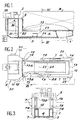
- the vehicle shown in Figures 1, 2, and 3 has two main parts: an elongated lower part 1 having a low height and intended for interventions on the bottom of floating structures, and a turret 2 located at the rear end of the part lower 1 and intended for interventions on the live works of the lateral faces of floating structures.
- the lower part 1 is fully submerged and, in this embodiment, the turret 2 partially emerges.
- Ballasts 7 in compartments are fixed on the sides of the lower part 1 and of the turret 2; their filling and evacuation makes it possible to modify the immersion of the vehicle and can be done in sequence, so as to impart to the vehicle a pitching movement if necessary.
- the lower part 1 and the turret 2 are isolated from the surrounding water by a shell 3 which also includes the ballasts 7.
- the interior of the lower part 1 forms a lower working compartment 4 whose height is slightly greater than that of 'a man who is almost devoid of partitions and obstacles; the interior of the turret 2 houses the vehicle control mechanisms and therefore in particular comprises a control and propulsion room 5 on the rear; a lateral working compartment 6 is adjacent to the control and propulsion compartment 5 and located in front of it. It communicates through its lower part with the rear part of the lower working compartment 4.
- a watertight transverse partition 26 separates the control and propulsion compartment 5 from the working compartments 4 and 6.
- hydrojets a hydrojet 28 aft controls the longitudinal movements, two forward hydrojets 29 and two aft hydrojets 30, to port and starboard, control the lateral movements.
- the hydrojets are connected to a hydraulic system not shown.
- the lateral and lower working compartments 6 and 4 are partially delimited by a wall 11 of longitudinal extension and which forms part of the shell 3, so that they open respectively towards the front and upwards.
- the wall 11 is provided with an edge 12 perpendicular to it and which extends in a horizontal plane above the lower working compartment 4 and in a transverse plane in front of the lateral working compartment 6.
- the edge 12 has an overall shape which matches the shape of the living works of a partially submerged floating structure B.
- Structue B can be a ship docked or not docked, a barge, a dock, a platform or any structure.
- a seal 13 is arranged externally along the edge 12 below the water level.
- the water which filled the working compartments 4 and 6 could be evacuated by means of a pumping system comprising a pump 20 arranged in the room control and propulsion 5 and provided with a pipe 21 opening through the watertight partition 26 at the bottom of the lower working compartment 4.
- the seal 13 can be arranged in a closed line. It can also be arranged, as shown here, along an open line, the ends 13a of which are located on the front face of the turret 2 above the water line of the fully submerged vehicle.
- Stops 14 and 15 of low height are disposed respectively on the lower part 1 and on the turret 2, immediately around the joint 13. They are intended to ensure the contact of the vehicle with the floating structure B while leaving sufficient clearance for the joint 13 to inflate.
- FIG. 4a the vehicle approached near the floating structure B with the ballasts 7 not filled. Its motors still in motion, it then begins to fill the ballasts 7, possibly starting with those located at the rear.
- FIG. 4b represents: a pitching movement plunges the lower part 1 into the water, its rear being more depressed. Water gradually fills the working compartments 4 and 6.
- Figure 4c the immersion of the lower part 1 is now sufficient to allow it to pass under the floating structure B.
- the ballasts 7 continue to fill, and the vehicle gradually regains its trim.
- the lower part 1 of the vehicle is entirely under the floating structure B, while the front face of the turret 2 is in contact with the side wall of the floating structure B.
- This docking maneuver was carried out at low speed taking advantage of the wander of the vehicle
- the ballasts 7 are then emptied somewhat so as to operate an overall vertical translation of the vehicle bringing the upper face of its lower part 1 into contact with the bottom of the floating structure B.
- the hydrojets 28, 29 or 30 are possibly put into action to stabilize the vehicle.
- the contact of the lower part 1 of the vehicle with the floating structure B is maintained thanks to Archimedes' push only.
- the seal 13 is then inflated so as to isolate a water-tight volume between the floating structure B, the shell 3, the waterproof partition 26 and the seal 13.
- the water trapped in this volume is then pumped by means of the pump 20. It is important to note that from this moment the Archimedes' thrust acquires a longitudinal component which presses the vehicle against the floating structure B and thus automatically maintains the seal, without any clamping or securing system .
- This absence of mechanical linkage joined to a complete propulsion system enables the vehicle to be removed quickly, if necessary, which is therefore completely autonomous.
- the working compartments 4 and 6 are obviously provided with all the necessary arrangements such as lighting, energy supply, renewal of air, forklifts for handling heavy objects, etc.
- the working compartment 4 of the lower part 1 can be provided with an elevator 23 which can run longitudinally on rails 24.
- the vehicle When the work is to be carried out over a significant length of the live works, the vehicle is subjected to a translational maneuver which makes it possible to repeat the maintenance operations on an adjacent area of the live works of the floating structure B, after possibly a temporary deflation of the seal 13 and a new commissioning of the pump 20. It is obviously desirable that the hull shape of the floating structure B remains invariable, but this condition is not absolutely essential since the seal 13 is inflatable and can therefore maintain tightness in the case of slight variations in hull shape.
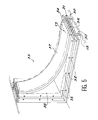
- the vehicle can be made up as shown in FIG. 5.
- the edge 12 is then provided with two trestles 30 parallel longitudinal on the lower part 1 and vertical on the turret 2.
- the trestles 30 support a fixing plate 31 provided with two rows of drilling 32 on its outer edges, which protrude from the trestles 30.
- a removable connecting piece 33 adjacent to the lower part 1 and to the turret 2 is placed on the fixing plate 31 by means of an apron 34 provided with two rows 35 of holes in correspondence with those 32 of the fixing plate 31. It is thus possible to assemble the latter to the apron 34 by bolts, a flat seal 36 having been interposed between them.
- the apron 34 carries a connection plate 37 by means of two parallel edges 38.
- the connection plate 37 has a shape adapted to the connection of the bottom and the plating of the floating structure B, which can be rectilinear and oblique or curved. It joins the apron 34 at its ends.
- the inflatable seal 13 is installed on the connection plate 37 and the fixing plate 31 in this design, which improves the interest of the vehicle. It is thus possible to have in reserve a large number of connecting pieces 33 of different sizes and shapes to adapt to various floating structures.
- the connecting pieces 33 may possibly extend over the greater part of the edge 12.
- the vehicle of the invention represents a completely interesting solution for all work concerning the live works of ships or flat-bottomed barges. However, it can also be adapted to oblique or special hulls. The construction with a flat bottom and a rear turret can then be modified. In addition, the vehicle can be either floating or underwater.
Landscapes
- Engineering & Computer Science (AREA)
- Mechanical Engineering (AREA)
- Ocean & Marine Engineering (AREA)
- Chemical & Material Sciences (AREA)
- Combustion & Propulsion (AREA)
- Transportation (AREA)
- Body Structure For Vehicles (AREA)
- Machines For Laying And Maintaining Railways (AREA)
Applications Claiming Priority (2)
| Application Number | Priority Date | Filing Date | Title |
|---|---|---|---|
| FR8802700A FR2628059B1 (fr) | 1988-03-03 | 1988-03-03 | Vehicule d'intervention sur une surface appartenant aux oeuvres vives d'une structure flottante |
| FR8802700 | 1988-03-03 |
Publications (2)
| Publication Number | Publication Date |
|---|---|
| EP0332500A1 true EP0332500A1 (de) | 1989-09-13 |
| EP0332500B1 EP0332500B1 (de) | 1992-04-29 |
Family
ID=9363873
Family Applications (1)
| Application Number | Title | Priority Date | Filing Date |
|---|---|---|---|
| EP89400552A Expired - Lifetime EP0332500B1 (de) | 1988-03-03 | 1989-02-28 | Fahrzeug für Unterhaltsarbeiten an Oberflächen von Unterwasserteilen von schwimmenden Strukturen |
Country Status (3)
| Country | Link |
|---|---|
| EP (1) | EP0332500B1 (de) |
| DE (1) | DE68901355D1 (de) |
| FR (1) | FR2628059B1 (de) |
Cited By (1)
| Publication number | Priority date | Publication date | Assignee | Title |
|---|---|---|---|---|
| US6676334B2 (en) * | 2002-06-10 | 2004-01-13 | Deepwater Technologies, Inc. | Work module support vessel |
Families Citing this family (1)
| Publication number | Priority date | Publication date | Assignee | Title |
|---|---|---|---|---|
| CN112829899B (zh) * | 2021-01-27 | 2022-04-05 | 中国检验认证集团河北有限公司 | 船舶压载水量确定方法和装置 |
Citations (2)
| Publication number | Priority date | Publication date | Assignee | Title |
|---|---|---|---|---|
| GB1281900A (en) * | 1968-09-12 | 1972-07-19 | Mitsubishi Heavy Ind Ltd | Submersible structures |
| GB1586237A (en) * | 1977-07-13 | 1981-03-18 | Hansen R S | Apparatus for use in the jointing of floating ship sections |
-
1988
- 1988-03-03 FR FR8802700A patent/FR2628059B1/fr not_active Expired - Lifetime
-
1989
- 1989-02-28 EP EP89400552A patent/EP0332500B1/de not_active Expired - Lifetime
- 1989-02-28 DE DE8989400552T patent/DE68901355D1/de not_active Expired - Lifetime
Patent Citations (2)
| Publication number | Priority date | Publication date | Assignee | Title |
|---|---|---|---|---|
| GB1281900A (en) * | 1968-09-12 | 1972-07-19 | Mitsubishi Heavy Ind Ltd | Submersible structures |
| GB1586237A (en) * | 1977-07-13 | 1981-03-18 | Hansen R S | Apparatus for use in the jointing of floating ship sections |
Cited By (1)
| Publication number | Priority date | Publication date | Assignee | Title |
|---|---|---|---|---|
| US6676334B2 (en) * | 2002-06-10 | 2004-01-13 | Deepwater Technologies, Inc. | Work module support vessel |
Also Published As
| Publication number | Publication date |
|---|---|
| DE68901355D1 (de) | 1992-06-04 |
| EP0332500B1 (de) | 1992-04-29 |
| FR2628059B1 (fr) | 1992-03-27 |
| FR2628059A1 (fr) | 1989-09-08 |
Similar Documents
| Publication | Publication Date | Title |
|---|---|---|
| US3447503A (en) | Method and apparatus for modular construction of a ship | |
| EP4110689B1 (de) | Schiff, das ein system zum anpassen eines abnehmbaren moduls umfasst, und angepasstes abnehmbares modul | |
| NO772306L (no) | Fremgangsm}te til transport og skip med lektere til utf¦relse av fremgangsm}ten | |
| US20040089212A1 (en) | Modular floating boat lift having aqueous hydraulic cylinder powered cradle | |
| US3641774A (en) | Method and apparatus for fabricating an offshore structure | |
| KR930016310A (ko) | 선박동체의 건조기술 및 방법 | |
| US3638437A (en) | Floatable casting for working on hull structures below water level | |
| EP0332500B1 (de) | Fahrzeug für Unterhaltsarbeiten an Oberflächen von Unterwasserteilen von schwimmenden Strukturen | |
| WO2004069646B1 (fr) | Navire sauveteur pour navire en detresse, procede de sauvetage de navire, et application d’un navire sauveteur | |
| FR2563166A1 (fr) | Systeme amphibie pour le remorquage et le lancement d'aeroglisseurs et d'embarcations cotieres | |
| EP4121345B1 (de) | System zur handhabung von meeres- oder unterwasserdrohnen durch einen schwimmenden ponton mit einem abnehmbaren drohnenschnittstellenmodul, angepasstes schiff | |
| FR2528005A1 (fr) | Dispositif pour la mise en cale seche de bateaux | |
| USRE29413E (en) | Method and apparatus for fabricating an off-shore structure | |
| EP0169781B1 (de) | Vorrichtung für das Anbordnehmen von Wasserfahrzeugen auf Schiffe | |
| FR2755661A1 (fr) | Dispositif de mise hors de l'eau de bateaux | |
| FR2506716A1 (fr) | Installation pour la mise a l'eau, ou hors d'eau, d'un navire | |
| FR2541648A1 (fr) | Structure de multicoque a nacelle articulee permettant le redressement apres chavirage | |
| FR2473008A1 (fr) | Bateau, en particulier drague a tremie de succion trainante, comportant un bras de nettoyage de la surface de l'eau | |
| US4292914A (en) | Method and apparatus for facilitating underwater work on ship hulls and like objects | |
| US3356058A (en) | Log transporting vessel | |
| KR101302206B1 (ko) | 선박용 추진기 설치방법 | |
| BG61969B1 (bg) | Метод за свързване на модули на плавателни съдове | |
| FR2805241A1 (fr) | Bateau specialise dans le ramassage des matieres flottantes et plus specialement les hydrocarbures petroliers | |
| US3183870A (en) | Dumping barge with pivoted side rails | |
| SU1309473A1 (ru) | Судно ледового плавани |
Legal Events
| Date | Code | Title | Description |
|---|---|---|---|
| PUAI | Public reference made under article 153(3) epc to a published international application that has entered the european phase |
Free format text: ORIGINAL CODE: 0009012 |
|
| AK | Designated contracting states |
Kind code of ref document: A1 Designated state(s): DE FR GB |
|
| 17P | Request for examination filed |
Effective date: 19900216 |
|
| 17Q | First examination report despatched |
Effective date: 19910429 |
|
| GRAA | (expected) grant |
Free format text: ORIGINAL CODE: 0009210 |
|
| AK | Designated contracting states |
Kind code of ref document: B1 Designated state(s): DE FR GB |
|
| REF | Corresponds to: |
Ref document number: 68901355 Country of ref document: DE Date of ref document: 19920604 |
|
| GBT | Gb: translation of ep patent filed (gb section 77(6)(a)/1977) | ||
| PLBE | No opposition filed within time limit |
Free format text: ORIGINAL CODE: 0009261 |
|
| STAA | Information on the status of an ep patent application or granted ep patent |
Free format text: STATUS: NO OPPOSITION FILED WITHIN TIME LIMIT |
|
| 26N | No opposition filed | ||
| PGFP | Annual fee paid to national office [announced via postgrant information from national office to epo] |
Ref country code: DE Payment date: 19940204 Year of fee payment: 6 |
|
| PGFP | Annual fee paid to national office [announced via postgrant information from national office to epo] |
Ref country code: GB Payment date: 19940218 Year of fee payment: 6 |
|
| PGFP | Annual fee paid to national office [announced via postgrant information from national office to epo] |
Ref country code: FR Payment date: 19950222 Year of fee payment: 7 |
|
| PG25 | Lapsed in a contracting state [announced via postgrant information from national office to epo] |
Ref country code: GB Effective date: 19950228 |
|
| GBPC | Gb: european patent ceased through non-payment of renewal fee |
Effective date: 19950228 |
|
| PG25 | Lapsed in a contracting state [announced via postgrant information from national office to epo] |
Ref country code: DE Effective date: 19951101 |
|
| PG25 | Lapsed in a contracting state [announced via postgrant information from national office to epo] |
Ref country code: FR Effective date: 19961031 |
|
| REG | Reference to a national code |
Ref country code: FR Ref legal event code: ST |