EP0332176A2 - Magnetanordnung zur Anwendung in einem Bilderzeugungssystem mittels magnetischer Resonanz - Google Patents
Magnetanordnung zur Anwendung in einem Bilderzeugungssystem mittels magnetischer Resonanz Download PDFInfo
- Publication number
- EP0332176A2 EP0332176A2 EP89104124A EP89104124A EP0332176A2 EP 0332176 A2 EP0332176 A2 EP 0332176A2 EP 89104124 A EP89104124 A EP 89104124A EP 89104124 A EP89104124 A EP 89104124A EP 0332176 A2 EP0332176 A2 EP 0332176A2
- Authority
- EP
- European Patent Office
- Prior art keywords
- magnetic
- magnetic field
- degree
- terized
- charac
- Prior art date
- Legal status (The legal status is an assumption and is not a legal conclusion. Google has not performed a legal analysis and makes no representation as to the accuracy of the status listed.)
- Granted
Links
Images


Classifications
-
- G—PHYSICS
- G01—MEASURING; TESTING
- G01R—MEASURING ELECTRIC VARIABLES; MEASURING MAGNETIC VARIABLES
- G01R33/00—Arrangements or instruments for measuring magnetic variables
- G01R33/20—Arrangements or instruments for measuring magnetic variables involving magnetic resonance
- G01R33/28—Details of apparatus provided for in groups G01R33/44 - G01R33/64
- G01R33/38—Systems for generation, homogenisation or stabilisation of the main or gradient magnetic field
- G01R33/381—Systems for generation, homogenisation or stabilisation of the main or gradient magnetic field using electromagnets
- G01R33/3815—Systems for generation, homogenisation or stabilisation of the main or gradient magnetic field using electromagnets with superconducting coils, e.g. power supply therefor
-
- G—PHYSICS
- G01—MEASURING; TESTING
- G01R—MEASURING ELECTRIC VARIABLES; MEASURING MAGNETIC VARIABLES
- G01R33/00—Arrangements or instruments for measuring magnetic variables
- G01R33/20—Arrangements or instruments for measuring magnetic variables involving magnetic resonance
- G01R33/28—Details of apparatus provided for in groups G01R33/44 - G01R33/64
- G01R33/42—Screening
- G01R33/421—Screening of main or gradient magnetic field
Definitions
- the present invention relates to a magnet apparatus for use in a magnetic resonance imaging system (MRI system) and, more particularly, to a magnet apparatus having a magnetic shield for reducing a magnetic fringe field.
- MRI system magnetic resonance imaging system
- An MRI apparatus is provided with a bore, and a working volume where a portion to be diagnosed of a patient is located is defined in the bore.
- a magnet apparatus has a main superconducting coil which is arranged to surround the bore and generates a static or main magnetic field in the working volume.
- a gradient magnetic field is superposed on the static magnetic field, and a high-frequency signal is applied to the portion to be diagnosed of the patient. As a result, a magnetic resonance signal generated by the portion to be diagnosed is detected, thus obtaining a tomographic image of the portion.
- the magnetic fringe field often magnetically adversely influences a portion around the MRI apparatus.
- a magnetic shield for reducing the magnetic fringe field is provided to the magnet apparatus.
- the magnetic shield a yoke magnetic shield and an active magnetic shield are known.
- the yoke magnetic shield comprises a cylindrical member surrounding the static magnetic field superconducting coil and formed of a ferromagnetic member.
- the magnetic fluxes leaking from the bore are absorbed by the magnetic shield, thus reducing the magnetic fringe field.
- an amount of leaking magnetic fluxes is also increased.
- an amount of a magnetic material of the cylindrical member must be increased in correspondence with an increase in intensity of the static magnetic field. As a result, the weight of the magnetic shield is considerably increased.
- a magnetic shield formed of about 5 tons of iron can provide a 5-Gauss magnetic fringe field region of about 40 m2.
- a magnetic shield formed of about 40 tons of iron is required so as to provide a 5-Gauss magnetic fringe field region of the same area. It is impossible to install an MRI system comprising such a magnetic shield in an existing hospital.
- the active magnetic shield comprises a second superconducting magnetic coil for generating a second magnetic field in a direction opposite to that of the magnetic field generated by the main superconducting coil in the working volume.
- the intensity of the magnetic field generated by the main coil is almost equal to that of the magnetic field generated by the second coil. For this reason, leaking magnetic fluxes of these two magnetic fields cancel each other, thus reducing the magnetic fringe field.
- the two magnetic fields are synthesized to form a static magnetic field. A difference between the intensities of the two magnetic fields is set to provide a predetermined static magnetic field intensity.
- the active magnetic shield does not require a ferromagnetic member, its weight is smaller than the yoke magnetic shield.
- a current flowing through the second coil can be adjusted so as to control a suppression amount of the leaking magnetic fluxes.
- the magnet apparatus has high manufacturing cost.
- the second coil is arranged radially outside the main coil. For this reason, the outer diameter of the magnet apparatus is considerably increased. As a result, when the magnet apparatus is transported or when the magnet apparatus is installed, a very large transportation space and installation space are necessary. An existing hospital often does not have such a large transportation space and installation space, and a passage and installation space in the hospital must sometimes be reconstructed or additionally constructed. Therefore, it is difficult to transport and install the magnet apparatus.
- magnetic members such as reinforcements arranged in columns and floors are provided.
- the magnetic flux densities of the magnetic fluxes of the two magnetic fields may be changed by these magnetic members outside the bore.
- the magnetic fluxes whose density is changed may enter the working volume of the bore. As a result, homogeneity of the magnetic field in the working volume is deteriorated, and MRI diagnosis is disturbed.
- a magnet apparatus for use in a magnetic resonance imaging system, the system having a bore housing an object to be examined, and a working volume where a portion to be diagnosed of the object to be examined is located being defined in the bore, the magnetic apparatus comprising a first superconducting coil assembly, arranged radially outside the bore, for generating a first magnetic field in the working volume, an active magnetic shield including a second superconducting coil assembly, arranged radially outside the bore and electrically connected in series with the first superconducting coil assembly, for generating a second magnetic field in a direction opposite to the direction of the first magnetic field in the working volume, and a yoke magnetic shield, arranged radially outside the first superconducting coil assembly and the active magnetic shield and formed of a ferromagnetic member, whereby most of magnetic fluxes of the first and second magnetic fields leaking outside the bore cancel each other to be weakened and are absorbed in the yok
- means for setting a synthesized magnetic field in the working volume at a high homogeneity is arranged.
- a magnetic fringe field can be reduced by cooperation of an active magnetic shield and a yoke magnetic shield, and the synthesized magnetic field in the working volume is maintained at a high homogeneity. For this reason, the volumes of the active and yoke magnetic shields can be reduced to be smaller than those of the conventional shields.
- the magnet apparatus can be rendered compact and light in weight.
- the magnet apparatus can be easily carried and installed in an existing hospital or the like.
- an amount of use of a superconducting wire can be reduced, and the manufacturing cost of the magnet apparatus can be reduced.
- a magnetic fringe field is absorbed by the yoke magnetic shield. For this reason, a magnetic fringe field reaching ferromagnetic members such as reinforcements arranged in columns and floors can be eliminated. Thus, a magnetic fringe field whose magnetic flux density is changed by these ferromagnetic members enters the working volume less often. Therefore, homogeneity of the magnetic field in the working volume can be prevented from being deteriorated by the influence of the ferromagnetic members such as reinforcements arranged in columns and floors.
- Fig. 1 shows a magnetic resonance imaging system (MRI system) in which a magnet apparatus as an object of the present invention is applied is used.
- MRI system magnetic resonance imaging system
- a patient 1 lying on a couch 2 is housed in a warm bore 7.
- a portion to be diagnosed of the patient 1 is located in a working volume 18.
- a magnet apparatus 6 generates a static or main magnetic field in the working volume 18 along a Z axis.
- the magnet apparatus 6 is connected to an excitation power source 8.
- X, Y, and Z gradient magnetic field coils 5 are arranged radially inside the magnet apparatus 6. These coils 5 are connected to excitation power sources 11, 12, and 13, respectively.
- an RF coil 3 is arranged to surround the portion to be diagnosed of the patient 1.
- the RF coil 3 is connected to an RF transmitter 15 and an RF receiver 16.
- the RF transmitter 15, the RF receiver 16, and the excitation power sources 11, 12, and 13 are connected to a central control unit 14.
- the control unit 14 is connected to a display/operation console 17.
- the magnet apparatus 6 is excited, and as a result, generates a uniform static magnetic field in the working volume.
- X, Y, and Z gradient magnetic fields generated by the X, Y, and Z gradient magnetic field coils 5 are superposed on the static magnetic field.
- the RF transmitter 15 is driven by a pulse sequence to apply a pulse signal.
- a magnetic resonance signal is induced in the portion to be diagnosed of the patient.
- the magnetic resonance signal is detected by the RF coil 3, and is fetched in the central control unit 14 through the RF receiver 16.
- the central control unit 14 performs image reproduction processing to obtain image data.
- the image data is converted to a video signal, and a tomographic image is displayed on the display/operation console 17.
- the magnet apparatus 6 of the present invention comprises a first superconducting coil assembly 26 for generating a first magnetic field constituting most part of the static magnetic field, a cooling means for cooling the superconducting coil, and a means for reducing a magnetic field leaking outside the magnet apparatus 6.
- the first superconducting coil assembly 26 surrounds the warm bore 7, and extends along the Z axis.
- a mid-plane 29 (X-Y plane) of the magnet apparatus 6 is defined to be perpendicular to the Z axis.
- the first superconducting coil assembly 26 includes a plurality of coaxial coils symmetrically arranged with reference to the mid-plane 29.
- the cooling means is constituted by a liquid helium tank 28 filled with a liquid helium and housing the superconducting coil assembly 26, a plurality of heat radiation shield plates 30 covering the liquid helium tank 28, multilayered heat insulating members 31 housed between the adjacent heat radiation shield plates 30, and a vacuum container 32 which covers the heat radiation shield plates 30 and the interior of which is kept in a vacuum state.
- the vacuum chamber 32 is supported on legs 33.
- the cooling means keeps the first superconducting coil assembly 26 at a cryogenic state of 4.2 K.
- the characteristic feature of the present invention is that the means for eliminating the magnetic fringe field comprises an active magnetic shield 27 and a yoke (passive) magnetic shield 19.
- the active magnetic shield 27 comprises a second superconducting coil assembly which is coaxially arranged radially outside the first coil assembly 26.
- the second superconducting coil assembly includes a plurality of coaxial coils which are symmetrically arranged with reference to the mid-plane 29. Further additionally, the second superconducting coil assembly is housed in the liquid helium tank 28 and is cooled to 4.2 K.
- the second superconducting coil assembly is connected in series with the first superconducting coil assembly 26, and generates a second magnetic field in a direction opposite to that of the first magnetic field in the working volume 18.
- the yoke magnetic shield 19 comprises a cylindrical shell member 20 formed of a ferromagnetic material such as iron and attached on the outer periphery of the vacuum chamber 32, and legs 34 supporting the shell member 20 and coupled to the legs 33 through coupling plates 35.
- the shell member 20 is arranged concentrically with the first and second superconducting coil assemblies about the Z axis. Furthermore, the shell member 20 is divided into two segments with reference to the mid-plane 29 (X-Y plane). Each of these segments is further divided into two pieces with reference a vertical plane (Y-Z plane) along the Z axis. More specifically, the shell member 20 is divided into four pieces. The length of the shell member 20 along the Z axis is shorter than that of the second superconducting coil assembly.
- the direction of the first magnetic field is opposite to that of the second magnetic field. For this reason, the magnetic fluxes of the first magnetic field leaking from the bore 7 and those of the second magnetic field leaking therefrom cancel each other to be weakened. The weakened magnetic fluxes are absorbed in the yoke magnetic shield 19. Thus, the leaking magnetic field is reduced.
- the yoke magnetic shield electromagnetically forms a third magnetic field in the working volume 18. More specifically, some of the leaking magnetic fluxes of the first and second magnetic fields are magnetically changed by the yoke magnetic shield and enter the working volume 18 to form the third magnetic field. For this reason, the first to third magnetic fields are present in the working volume 18, and form a synthesized magnetic field.
- the magnetic field in the working volume 18 is required to have a high homogeneity, e.g., homogeneity of 20 ppm or less.
- the synthesized magnetic field of the first to third magnetic fields in the working volume 18 is required to have a high homogeneity.
- the following means for setting the synthesized magnetic field at a high homogeneity is arranged.
- the intensity of the first magnetic field generated by the first superconducting coil assembly is expressed by a component of a term of degree 0 (degree-0 term component) and components of terms of higher degrees (higher-degree term components, i.e., error components), and is series-developed as follows:
- B M first magnetic field intensity
- B 0M degree-0 term component higher-degree term components
- b iM term of degree i of the higher-degree term components
- the intensity of the second magnetic field generated by the active magnetic shield is expressed by a degree-0 term component and higher-degree term components, and is series-developed as follows:
- B A first magnetic field intensity
- B 0A degree-0 term component higher-degree term components
- b iA term of degree i of the higher-degree term components
- the intensity of the third magnetic field generated by the yoke magnetic shield is expressed by a degree-0 term component and higher-degree term components, and is series-developed as follows:
- B Y first magnetic field intensity
- B 0Y degree-0 term component higher-degree term components
- b iY term of degree i of the higher-degree term components
- the intensity of the synthesized magnetic field is expressed by degree-0 term components and higher-degree term components as follows:
- the intensity of the synthesized magnetic field consists of only the degree-0 term components.
- the synthesized magnetic field is set at a high homogeneity.
- the numbers of turns of the superconducting wires of the first and second superconducting coil assemblies and the amount of the ferromagnetic member of the yoke magnetic shield are determined so that the sums of the terms of the same degrees of the higher-degree term components of the first to third magnetic fields are set to be substantially zero, that is, b 1M - b 1A + b 1Y 0, b 2M - b 2A + b 2Y 0,..., b iM - b iA + b iY 0.
- the intensity of the synthesized magnetic field is defined by only the degree-0 term components B 0M - B 0A + B 0Y , and the synthesized magnetic field is set at a high homogeneity.
- the means for setting the higher-degree term components of the synthesized magnetic fields to be substantially zero may be arranged as follows.
- the number of turns of the superconducting wire of the first superconducting coil assembly is set, so that the terms of the higher-degree term components of the first magnetic field are set to be substantially zero, that is, b 1M 0, b 2M 0,..., b iM 0. Furthermore, the number of turns of the superconducting wire of the second superconducting coil assembly and the amount of the magnetic member of the yoke magnetic shield are set so that the sums of the terms of the same degrees of the higher-degree term components of the second and third magnetic fields are set to be substantially zero, that is, -b 1A + b 1Y 0, -b 2A + b 2Y 0,..., -b iA + b iY 0. In this case, the intensity of the synthesized magnetic field is defined by only the degree-0 term components, and the synthesized magnetic field is set at a high homogeneity.
- the means for setting the higher-degree term components of the synthesized magnetic fields to be substantially zero may be arranged as follows.
- the number of turns of the superconducting wire of the second superconducting coil assembly is set, so that the terms of the higher-degree term components of the second magnetic field are set to be substantially zero, that is, b 1A 0, b 2A 0,..., b iA 0. Furthermore, the number of turns of the superconducting wire of the first superconducting coil assembly and the amount of the magnetic member of the yoke magnetic shield are set so that the sums of the terms of the same degrees of the higher-degree term components of the first and third magnetic fields are set to be substantially zero, that is, b 1M + b 1Y 0, -b 2M + b 2Y 0,..., b iM + b iY 0. In this case, the intensity of the synthesized magnetic field is defined by only the degree-0 term components, and the synthesized magnetic field is set at a high homogeneity.
- the magnetic fringe field is reduced by a cooperation of the active and yoke magnetic shields, and the synthesized magnetic field in the working volume 18 is set at a high homogeneity. For this reason, the volumes of the active and yoke magnetic shields can be reduced to be smaller than those of the conventional ones.
- the volume of the active magnetic shield can be reduced, the outer dimensions of the magnet apparatus can be reduced. For this reason, the MRI system can be rendered compact, and can be easily carried and installed in a hospital or the like. Since the volume of the active magnetic shield can be reduced, the amount of use of a superconducting wire can be reduced. Thus, an increase in manufacturing cost of the magnet apparatus can be suppressed.
- the volume of the yoke magnetic shield can be reduced, the weight of the yoke magnetic shield can be decreased.
- the MRI system can be easily carried and installed in a hospital or the like.
- the floor structure in the hospital need not be specially reinforced for installation of the MRI system in the hospital.
- the magnetic fringe field is absorbed by the yoke magnetic shield. For this reason, leaking magnetic fluxes reaching ferromagnetic members such as reinforcements arranged in columns and floors can be eliminated. For this reason, a leaking magnetic field whose magnetic flux density is changed by these magnetic members enters the working volume less often. Therefore, the homogeneity of the magnetic field in the working volume can be prevented from being deteriorated by the influence of the ferromagnetic members such as reinforcements arranged in columns and floors.
- the length, along the Z axis, of the shell member 20 of the yoke magnetic shield is smaller than that of the second superconducting coil. For this reason, disturbance of magnetic fluxes at the end portions of the magnet apparatus 6 in the Z direction can be eliminated. For this reason, the homogeneity of the magnetic field in the working volume 18 can be improved.
- the yoke magnetic shield 19 is divided into four pieces and these pieces are carried in a hospital or the like. The pieces are assembled in the hospital. Thus, carry-in and installation of the MRI system in the hospital can be further facilitated. Note that after assembly, the legs 33 of the magnet apparatus and the legs 34 of the yoke magnetic shield 19 are coupled through the coupling plates 35.
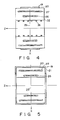
- a first modification of the present invention will be described below with reference to Fig. 4.
- a plurality of iron shims 36 are attached to the inner peripheral surface of the warm bore 7.
- the iron shims 36 serve to finely adjust the shape of lines of magnetic forces in the bore 7, thus improving homogeneity of the magnetic field in the working volume 18.
- the iron shims 36 electromagnetically form a fourth magnetic field in the working volume 18. More specifically, some of the magnetic fluxes of the first to third magnetic fields are magnetically changed by the iron shims 36, thus forming the fourth magnetic field in the working volume 18. For this reason, the first to fourth magnetic fields are present in the working volume 18, and form a synthesized magnetic field.
- a means for setting the synthesized magnetic field at a high uniformity level is arranged as follows.
- the intensity of the fourth magnetic field is expressed by a degree-0 term component and higher-degree term components (i.e., error components), and is series-developed as follows:
- B S first magnetic field intensity
- B 0S degree-0 term component higher-degree term components
- b iS term of degree i of the higher-degree term components
- the intensity of the synthesized magnetic field consists of only the degree-0 term components.
- the synthesized magnetic field is set at a high homogeneity.
- the numbers of turns of the superconducting wires of the first and second superconducting coil assemblies and the amounts of the magnetic members of the yoke magnetic shield and the iron shims are determined so that the sums of the terms of the same degrees of the higher-degree term components of the first to fourth magnetic fields is set to be substantially zero, that is, b 1M - b 1A + b 1Y + b 1S 0,..., b iM - b iA + b iY + b iS 0.
- the intensity of the synthesized magnetic field is defined by only the degree-0 term components B 0M - B 0A + B 0Y + B 0S , and the synthesized magnetic field is set at a high homogeneity.
- the means for setting the higher-degree term components of the synthesized magnetic fields to be substantially zero may be arranged as follows.
- the number of turns of the superconducting wire of the first superconducting coil assembly is set, so that the terms of the higher-degree term components of the first magnetic field are set to be substantially zero, that is, b 1M 0,..., b iM 0. Furthermore, the number of turns of the superconducting wire of the second superconducting coil assembly and the amounts of the magnetic members of the yoke magnetic shield and the iron shims are set so that the sums of the terms of the same degrees of the higher-degree term components of the second and fourth magnetic fields are set to be substantially zero, that is, -b 1A + b 1Y + b 1S 0,..., -b iA + b iY + b iS 0.
- the intensity of the synthesized magnetic field is defined by only the degree-0 term components, and the synthesized magnetic field is set at a high homogeneity.
- the means for setting the higher-degree term components of the synthesized magnetic fields to be substantially zero may be arranged as follows.
- the number of turns of the superconducting wire of the second superconducting coil assembly is set, so that the terms of the higher-degree term components of the second magnetic field are set to be substantially zero, that is, -b 1A 0,..., -b iA 0. Furthermore, the number of turns of the superconducting wire of the first superconducting coil assembly and the amounts of the magnetic members of the yoke magnetic shield and the iron shims are set so that the sums of the terms of the same degrees of the higher-degree term components of the first, third, and fourth magnetic fields are set to be substantially zero, that is, b 1M + b 1Y + b 1S 0,..., b iM + b iY + b iS 0.
- the intensity of the synthesized magnetic field is defined by only the degree-0 term components, and the synthesized magnetic field is set at a high homogeneity.
- the synthesized magnetic field in the working volume can be set at a high homogeneity, and a magnetic fringe field can be reduced.
- the yoke magnetic shield 19 has disk-shaped lid members 21 attached to two ends of the shell member 20.
- the lid members 21 can absorb magnetic fluxes leaking from the bore 7 along the z axis. As a result, the magnetic fringe field along the Z axis can be further reduced.
Applications Claiming Priority (2)
| Application Number | Priority Date | Filing Date | Title |
|---|---|---|---|
| JP52631/88 | 1988-03-08 | ||
| JP63052631A JPH01227407A (ja) | 1988-03-08 | 1988-03-08 | 磁気共鳴イメージング装置用磁石 |
Publications (3)
| Publication Number | Publication Date |
|---|---|
| EP0332176A2 true EP0332176A2 (de) | 1989-09-13 |
| EP0332176A3 EP0332176A3 (en) | 1990-12-27 |
| EP0332176B1 EP0332176B1 (de) | 1995-10-25 |
Family
ID=12920169
Family Applications (1)
| Application Number | Title | Priority Date | Filing Date |
|---|---|---|---|
| EP19890104124 Expired - Lifetime EP0332176B1 (de) | 1988-03-08 | 1989-03-08 | Magnetanordnung zur Anwendung in einem Bilderzeugungssystem mittels magnetischer Resonanz |
Country Status (3)
| Country | Link |
|---|---|
| EP (1) | EP0332176B1 (de) |
| JP (1) | JPH01227407A (de) |
| DE (1) | DE68924610T2 (de) |
Cited By (10)
| Publication number | Priority date | Publication date | Assignee | Title |
|---|---|---|---|---|
| NL9000955A (nl) * | 1989-04-23 | 1990-11-16 | Elscint Ltd | Geintegreerd actief afgeschermd magneetstelsel. |
| EP0414528A2 (de) * | 1989-08-23 | 1991-02-27 | General Electric Company | Ferromagnetische Kompensationsringe für Magnete hoher FeldstÀ¤rke |
| GB2215471B (en) * | 1988-02-03 | 1991-10-02 | Fuji Electric Co Ltd | Superconducting magnet |
| EP0459268A2 (de) * | 1990-05-31 | 1991-12-04 | Siemens Aktiengesellschaft | Aktiv geschirmter Magnet |
| FR2667948A1 (fr) * | 1990-10-12 | 1992-04-17 | Magnetech | Systeme magnetique a champ homogene de grande accessibilite. |
| EP1553423A1 (de) * | 2004-01-06 | 2005-07-13 | GE Medical Systems Global Technology Company LLC | Verfahren und Gerät für Kernspintomographie |
| US7365540B2 (en) | 2004-02-14 | 2008-04-29 | Bruker Biospin Gmbh | Hybrid magnet configuration |
| DE102008020107A1 (de) | 2008-04-22 | 2009-11-12 | Bruker Biospin Gmbh | Kompakte supraleitende Magnetanordnung mit aktiver Abschirmung, wobei die Abschirmspule zur Feldformung eingesetzt wird |
| GB2474343A (en) * | 2009-10-06 | 2011-04-13 | Bruker Biospin Gmbh | Superconducting Magnet with Active Shielding and Field Shaping |
| US9423477B2 (en) | 2010-02-24 | 2016-08-23 | Viewray Technologies, Inc. | Split magnetic resonance imaging system |
Families Citing this family (4)
| Publication number | Priority date | Publication date | Assignee | Title |
|---|---|---|---|---|
| JPH04240440A (ja) * | 1991-01-23 | 1992-08-27 | Toshiba Corp | Mri装置用マグネット |
| JP2006261335A (ja) * | 2005-03-16 | 2006-09-28 | Kobe Steel Ltd | 超電導マグネット装置 |
| WO2014171463A1 (ja) * | 2013-04-15 | 2014-10-23 | 株式会社東芝 | 磁気共鳴イメージング装置 |
| JP7134679B2 (ja) * | 2018-04-10 | 2022-09-12 | キヤノンメディカルシステムズ株式会社 | 磁気共鳴イメージング装置および静磁場補正方法 |
Citations (4)
| Publication number | Priority date | Publication date | Assignee | Title |
|---|---|---|---|---|
| EP0111218A2 (de) * | 1982-12-11 | 1984-06-20 | Bruker Analytische Messtechnik GmbH | Elektromagnet für die NMR-Tomographie |
| EP0251342A2 (de) * | 1983-11-11 | 1988-01-07 | Oxford Medical Limited | Magnetanordnung |
| GB2197487A (en) * | 1986-11-13 | 1988-05-18 | Toshiba Kk | Magnetic shield for a magnetic resonance magnet |
| GB2215471A (en) * | 1988-02-03 | 1989-09-20 | Fuji Electric Co Ltd | Superconducting magnet |
-
1988
- 1988-03-08 JP JP63052631A patent/JPH01227407A/ja active Granted
-
1989
- 1989-03-08 EP EP19890104124 patent/EP0332176B1/de not_active Expired - Lifetime
- 1989-03-08 DE DE1989624610 patent/DE68924610T2/de not_active Expired - Lifetime
Patent Citations (4)
| Publication number | Priority date | Publication date | Assignee | Title |
|---|---|---|---|---|
| EP0111218A2 (de) * | 1982-12-11 | 1984-06-20 | Bruker Analytische Messtechnik GmbH | Elektromagnet für die NMR-Tomographie |
| EP0251342A2 (de) * | 1983-11-11 | 1988-01-07 | Oxford Medical Limited | Magnetanordnung |
| GB2197487A (en) * | 1986-11-13 | 1988-05-18 | Toshiba Kk | Magnetic shield for a magnetic resonance magnet |
| GB2215471A (en) * | 1988-02-03 | 1989-09-20 | Fuji Electric Co Ltd | Superconducting magnet |
Non-Patent Citations (2)
| Title |
|---|
| IEEE TRANSACTIONS ON MAGNETICS, vol. MAG-23, no. 2, March 1987, pages 603-606, New York, US; A. ISHIYAMA et al.: "Optimal design of superconducting magnets for whole-body NMR imaging" * |
| REVIEW OF SCIENTIFIC INSTRUMENTS, vol. 56, no. 1, January 1985, pages 131-135, Woodbury, US; D.I. HOULT et al.: "Shimming a superconducting nuclear-magnetic-resonance imaging magnet with steel" * |
Cited By (25)
| Publication number | Priority date | Publication date | Assignee | Title |
|---|---|---|---|---|
| GB2215471B (en) * | 1988-02-03 | 1991-10-02 | Fuji Electric Co Ltd | Superconducting magnet |
| NL9000955A (nl) * | 1989-04-23 | 1990-11-16 | Elscint Ltd | Geintegreerd actief afgeschermd magneetstelsel. |
| GB2232771A (en) * | 1989-04-23 | 1990-12-19 | Elscint Ltd | Actively and passively shielded MR magnet |
| GB2232771B (en) * | 1989-04-23 | 1994-01-05 | Elscint Ltd | Integrated active shielded magnet system |
| EP0414528A2 (de) * | 1989-08-23 | 1991-02-27 | General Electric Company | Ferromagnetische Kompensationsringe für Magnete hoher FeldstÀ¤rke |
| EP0414528A3 (en) * | 1989-08-23 | 1991-07-31 | General Electric Company | Ferromagnetic compensation rings for high field strength magnets |
| EP0459268A2 (de) * | 1990-05-31 | 1991-12-04 | Siemens Aktiengesellschaft | Aktiv geschirmter Magnet |
| EP0459268A3 (en) * | 1990-05-31 | 1992-02-12 | Siemens Aktiengesellschaft | Actively screened magnet |
| FR2667948A1 (fr) * | 1990-10-12 | 1992-04-17 | Magnetech | Systeme magnetique a champ homogene de grande accessibilite. |
| WO1992007278A1 (fr) * | 1990-10-12 | 1992-04-30 | Sopha Imaging | Systeme magnetique a champ homogene de grande accessibilite |
| EP1553423A1 (de) * | 2004-01-06 | 2005-07-13 | GE Medical Systems Global Technology Company LLC | Verfahren und Gerät für Kernspintomographie |
| US7019525B2 (en) | 2004-01-06 | 2006-03-28 | Ge Medical Systems Glogal Technology Company, Llc | Method and apparatus for magnetic resonance imaging |
| US7365540B2 (en) | 2004-02-14 | 2008-04-29 | Bruker Biospin Gmbh | Hybrid magnet configuration |
| DE102008020107A1 (de) | 2008-04-22 | 2009-11-12 | Bruker Biospin Gmbh | Kompakte supraleitende Magnetanordnung mit aktiver Abschirmung, wobei die Abschirmspule zur Feldformung eingesetzt wird |
| US7898258B2 (en) | 2008-04-22 | 2011-03-01 | Bruker Biospin Gmbh | Compact superconducting magnet configuration with active shielding having a shielding coil contributing to field formation |
| DE102009045774A1 (de) | 2008-04-22 | 2011-04-28 | Bruker Biospin Gmbh | Kompakte supraleitende Magnetanordnung mit aktiver Abschirmung, wobei die Abschirmspule zur Feldformung eingesetzt wird |
| DE102008020107B4 (de) * | 2008-04-22 | 2011-08-25 | Bruker BioSpin GmbH, 76287 | Kompakte supraleitende Magnetanordnung mit aktiver Abschirmung, wobei die Abschirmspule zur Feldformung eingesetzt wird |
| DE102009045774B4 (de) * | 2008-04-22 | 2012-07-05 | Bruker Biospin Gmbh | Kompakte supraleitende Magnetanordnung mit aktiver Abschirmung, wobei die Abschirmspule zur Feldformung eingesetzt wird |
| GB2474343A (en) * | 2009-10-06 | 2011-04-13 | Bruker Biospin Gmbh | Superconducting Magnet with Active Shielding and Field Shaping |
| DE102009045373A1 (de) | 2009-10-06 | 2011-04-21 | Bruker Biospin Gmbh | Kompakte supraleitende Magnetanordnung mit aktiver Abschirmung, wobei die Abschirmspule das Feldmaximum der Hauptfeldspule dämpft |
| DE102009045373B4 (de) * | 2009-10-06 | 2011-12-08 | Bruker Biospin Gmbh | Kompakte supraleitende Magnetanordnung mit aktiver Abschirmung, wobei die Abschirmspule das Feldmaximum der Hauptfeldspule dämpft |
| US8154368B2 (en) | 2009-10-06 | 2012-04-10 | Bruker Biospin Gmbh | Compact superconducting magnet configuration with active shielding, wherein the shielding coil damps the field maximum of the main coil as well as associated magnetic resonance tomograph, NMR spectrometer and ion cyclotron resonance mass spectrometer |
| GB2474343B (en) * | 2009-10-06 | 2015-09-02 | Bruker Biospin Gmbh | Compact superconducting magnet configuration with active shielding, wherein the shielding coil damps the field maximum of the main coil |
| US9423477B2 (en) | 2010-02-24 | 2016-08-23 | Viewray Technologies, Inc. | Split magnetic resonance imaging system |
| US10571536B2 (en) | 2010-02-24 | 2020-02-25 | Viewray Technologies, Inc. | Split magnetic resonance imaging system |
Also Published As
| Publication number | Publication date |
|---|---|
| DE68924610D1 (de) | 1995-11-30 |
| JPH0471324B2 (de) | 1992-11-13 |
| DE68924610T2 (de) | 1996-04-11 |
| EP0332176A3 (en) | 1990-12-27 |
| JPH01227407A (ja) | 1989-09-11 |
| EP0332176B1 (de) | 1995-10-25 |
Similar Documents
| Publication | Publication Date | Title |
|---|---|---|
| EP0139308B1 (de) | Magnetischer Kernresonanzapparat | |
| EP0332176B1 (de) | Magnetanordnung zur Anwendung in einem Bilderzeugungssystem mittels magnetischer Resonanz | |
| EP0629875B1 (de) | Gradientenspule für magnetische Resonanz und Hochfrequenz-Abschirmung | |
| EP0433002B1 (de) | System zur Bilderzeugung mittels magnetischer Resonanz mit aktiv abgeschirmten Gradientenspulen | |
| EP0144171B1 (de) | Magnetanordnung | |
| US6157276A (en) | MRI magnet assembly with non-conductive inner wall | |
| EP0562708B1 (de) | Anordnungen von supraleitenden Magneten | |
| EP0138270B1 (de) | Magnetischer Kernresonanzapparat | |
| CN106716166A (zh) | 可运输磁共振成像系统 | |
| EP0167243B1 (de) | Magnetische Struktur | |
| US5084677A (en) | Magnetic field generating apparatus | |
| US5396208A (en) | Magnet system for magnetic resonance imaging | |
| US6965236B2 (en) | MRI system utilizing supplemental static field-shaping coils | |
| GB2229820A (en) | Compact shielded gradient coil system | |
| EP0488464B1 (de) | Kernspinresonanzapparat mit einem supraleitenden Abschirmmagneten | |
| US5581223A (en) | Superconducting magnet | |
| US4931759A (en) | Magnetic resonance imaging magnet having minimally symmetric ferromagnetic shield | |
| JPH0268038A (ja) | 磁気共鳴イメージング装置の超電導マグネット | |
| WO1989004049A1 (en) | Magnet assembly | |
| GB2162641A (en) | Nuclear magnetic resonance | |
| US5928147A (en) | Magnetic resonance imaging apparatus | |
| JPH0449948A (ja) | Mri装置 | |
| JPH02195937A (ja) | 磁気共鳴イメージング装置用静磁界磁石 | |
| Andrew et al. | Magnetic shielding of magnetic resonance systems | |
| JPH047808A (ja) | 核磁気共鳴断層撮影装置の超電導マグネット用低温容器 |
Legal Events
| Date | Code | Title | Description |
|---|---|---|---|
| PUAI | Public reference made under article 153(3) epc to a published international application that has entered the european phase |
Free format text: ORIGINAL CODE: 0009012 |
|
| 17P | Request for examination filed |
Effective date: 19890405 |
|
| AK | Designated contracting states |
Kind code of ref document: A2 Designated state(s): DE GB NL |
|
| PUAL | Search report despatched |
Free format text: ORIGINAL CODE: 0009013 |
|
| AK | Designated contracting states |
Kind code of ref document: A3 Designated state(s): DE GB NL |
|
| 17Q | First examination report despatched |
Effective date: 19930504 |
|
| GRAA | (expected) grant |
Free format text: ORIGINAL CODE: 0009210 |
|
| AK | Designated contracting states |
Kind code of ref document: B1 Designated state(s): DE GB NL |
|
| REF | Corresponds to: |
Ref document number: 68924610 Country of ref document: DE Date of ref document: 19951130 |
|
| PLBE | No opposition filed within time limit |
Free format text: ORIGINAL CODE: 0009261 |
|
| STAA | Information on the status of an ep patent application or granted ep patent |
Free format text: STATUS: NO OPPOSITION FILED WITHIN TIME LIMIT |
|
| 26N | No opposition filed | ||
| REG | Reference to a national code |
Ref country code: GB Ref legal event code: IF02 |
|
| PGFP | Annual fee paid to national office [announced via postgrant information from national office to epo] |
Ref country code: GB Payment date: 20080305 Year of fee payment: 20 Ref country code: NL Payment date: 20080303 Year of fee payment: 20 |
|
| PGFP | Annual fee paid to national office [announced via postgrant information from national office to epo] |
Ref country code: DE Payment date: 20080306 Year of fee payment: 20 |
|
| REG | Reference to a national code |
Ref country code: GB Ref legal event code: PE20 Expiry date: 20090307 |
|
| NLV7 | Nl: ceased due to reaching the maximum lifetime of a patent |
Effective date: 20090308 |
|
| PG25 | Lapsed in a contracting state [announced via postgrant information from national office to epo] |
Ref country code: NL Free format text: LAPSE BECAUSE OF EXPIRATION OF PROTECTION Effective date: 20090308 |
|
| PG25 | Lapsed in a contracting state [announced via postgrant information from national office to epo] |
Ref country code: GB Free format text: LAPSE BECAUSE OF EXPIRATION OF PROTECTION Effective date: 20090307 |
|
| PG25 | Lapsed in a contracting state [announced via postgrant information from national office to epo] |
Ref country code: DE Free format text: LAPSE BECAUSE OF EXPIRATION OF PROTECTION Effective date: 20090308 |