EP0332084A2 - Dispositif de rétraction d'un volet aérodynamique - Google Patents
Dispositif de rétraction d'un volet aérodynamique Download PDFInfo
- Publication number
- EP0332084A2 EP0332084A2 EP89103789A EP89103789A EP0332084A2 EP 0332084 A2 EP0332084 A2 EP 0332084A2 EP 89103789 A EP89103789 A EP 89103789A EP 89103789 A EP89103789 A EP 89103789A EP 0332084 A2 EP0332084 A2 EP 0332084A2
- Authority
- EP
- European Patent Office
- Prior art keywords
- carry bar
- retracting device
- air spoiler
- spoiler
- casing
- Prior art date
- Legal status (The legal status is an assumption and is not a legal conclusion. Google has not performed a legal analysis and makes no representation as to the accuracy of the status listed.)
- Granted
Links
Images
Classifications
-
- B—PERFORMING OPERATIONS; TRANSPORTING
- B62—LAND VEHICLES FOR TRAVELLING OTHERWISE THAN ON RAILS
- B62D—MOTOR VEHICLES; TRAILERS
- B62D35/00—Vehicle bodies characterised by streamlining
- B62D35/005—Front spoilers
-
- Y—GENERAL TAGGING OF NEW TECHNOLOGICAL DEVELOPMENTS; GENERAL TAGGING OF CROSS-SECTIONAL TECHNOLOGIES SPANNING OVER SEVERAL SECTIONS OF THE IPC; TECHNICAL SUBJECTS COVERED BY FORMER USPC CROSS-REFERENCE ART COLLECTIONS [XRACs] AND DIGESTS
- Y02—TECHNOLOGIES OR APPLICATIONS FOR MITIGATION OR ADAPTATION AGAINST CLIMATE CHANGE
- Y02T—CLIMATE CHANGE MITIGATION TECHNOLOGIES RELATED TO TRANSPORTATION
- Y02T10/00—Road transport of goods or passengers
- Y02T10/80—Technologies aiming to reduce greenhouse gasses emissions common to all road transportation technologies
- Y02T10/82—Elements for improving aerodynamics
-
- Y—GENERAL TAGGING OF NEW TECHNOLOGICAL DEVELOPMENTS; GENERAL TAGGING OF CROSS-SECTIONAL TECHNOLOGIES SPANNING OVER SEVERAL SECTIONS OF THE IPC; TECHNICAL SUBJECTS COVERED BY FORMER USPC CROSS-REFERENCE ART COLLECTIONS [XRACs] AND DIGESTS
- Y10—TECHNICAL SUBJECTS COVERED BY FORMER USPC
- Y10T—TECHNICAL SUBJECTS COVERED BY FORMER US CLASSIFICATION
- Y10T74/00—Machine element or mechanism
- Y10T74/18—Mechanical movements
- Y10T74/18568—Reciprocating or oscillating to or from alternating rotary
- Y10T74/18576—Reciprocating or oscillating to or from alternating rotary including screw and nut
- Y10T74/18712—Contamination related
- Y10T74/1872—Imperforate enclosure
Definitions
- the present invention relates in general to an air spoiler mounted to a front lower portion of a motor vehicle, and more particularly to a device for retracting the air spoiler. More specifically, the present invention is concerned with an air spoiler retracting device which moves the air spoiler linearly up and down.
- Some of the chin spoilers are of a retractable type in which the spoiler proper is kept retracted in a container area of the vehicle when the vehicle is at no or low speed, but the same becomes exposed to the outside of the vehicle when the vehicle reaches critical speeds where such device is effective or beneficial.
- Japanese Patent First Provisional Publications Nos. 59-156875 and 61-222875 show some of the chin spoilers of such retractable type.
- the retractable chin spoilers disclosed by the publications are bulky in size.
- the retracting devices of these chin spoilers are bulkily constructed and thus there is a need of providing the vehicle body with an enlarged area for mounting of the spoiler arrangement.
- an air spoiler retracting device which comprises a casing; a reversible electric motor disposed in the casing and having a drive shaft; a carry bar held by the casing and axially movable in parallel with the axis of the drive shaft, the carry bar having one end to which a spoiler proper is connected; a first transmission mechanism including a first gear driven by the drive shaft of the motor and a second gear meshed with the first gear; a second transmission mechanism for converting the rotational movement of the second gear to the axial movement of the carry bar; first means for permitting a pivotal movement of the carry bar relative to the second transmission mechanism; and second means for assisting the function of the first means, the second means including at least one elastomeric member sandwiched between attached two parts.
- FIG. 1 there is shown a passenger motor vehicle to which the present invention is practically applied.
- denoted by numeral 1 is a vehicle body
- 2 is a front air spoiler (viz., chin spoiler)
- 3 is a spoiler retracting device mounted at each side of a front portion of the vehicle body 1. Due to operation of the two retracting devices 3, the air spoiler proper 2 is moved substantially vertically between a lower or operative position as shown by a solid line and an upper or retracted position as shown by a phantom line.
- the two retracting devices 3 are substantially the same in construction except for a symmetrical relation with which the corresponding parts of the devices are arranged, the following description will be directed to only one device, that is, the device 3 shown by a solid line, for avoiding repeated explanation.
- FIG. 2 there is shown an air spoiler retracting device 3 which is a first embodiment of the present invention.
- the device 3 comprises a rectangular casing 8 which is secured through mounting means 7 to a bracket 4 secured to the vehicle body 1.
- the mounting means 7 includes bolts 5 and elastomeric mounts 6.
- a lid 9 is bolted to the casing 8 to cover the interior of the same.
- a reversible electric motor 11 is disposed in an upper left part of the interior of the casing 8 having its drive shaft 10 directed downward.
- a helical gear 13 which has a shaft 12 coaxial with the drive shaft 10 of the motor 11.
- Two bearings 14 are used for rotatably holding the shaft 12.
- the shaft 12 is connected to the drive shaft 10 of the motor 11 by means of a coupling 15 to be driven by the motor.
- a threaded shaft 16 is rotatably disposed in the casing 8 beside the motor 11, which extends in parallel with the drive shaft 10 of the motor 11.
- Upper and lower bearings 17 are mounted to the casing 8 for bearing the threaded shaft 16.
- the threaded shaft 16 has as its lower part a helical gear 18 which is meshed with the above-mentioned helical gear 13.
- the coupling 15 and the two helical gears 13 and 18 constitute a so-called "transmission mechanism" 19 through which the threaded shaft 16 is operatively connected to the drive shaft 10 of the motor 11. That is, upon energization of the motor 11, the threaded shaft 16 is rotated in one or the other direction about the axis thereof.
- Meshed with an external thread 16a of the threaded shaft 16 is a threaded bore 21 of a rectangular nut 20.
- Designated by numeral 22 is a slider which is positioned at a right side, as viewed in Fig. 2, of the interior of the casing 8.
- the slider 22 is movable in parallel with the axis of the threaded shaft 16.
- the slider 22 has at its leading end portion a rectangular bore 23 in which the rectangular nut 20 is received.
- Upper and lower walls of the rectangular bore 23 are formed with respective openings 24 through which the threaded shaft 16 passes to engage with the rectangular nut 20.
- the upper and lower walls of the bore 23 are respectively equipped with elastomeric members 50 and 52 absorbing a shock produced when the slider 22 is brought into contact with upper and lower stopper portions of the casing 8.
- the size of the rectangular bore 23 is somewhat larger than that of the rectangular nut 20, so that the nut 20 can play somewhat in the bore 23.
- the rectangular bore 23 is formed larger than the rectangular nut 20 by a degree corresponding to the clearances denoted by "l1" and "l2".
- the openings 24 of the upper and lower walls of the bore 23 are slightly larger in diameter than the threaded shaft 16.
- the leading end of the slider 22 has upper and lower cuts 22a and 22b which are merged with the rectangular bore 23.
- the upper and lower elastomeric members 50 and 52 have respective bores through which the threaded shaft 16 passes.
- a carry bar 25 extends downwardly from the casing 8, which is pivotally connected at its upper end to the slider 22.
- a pivot pin 26 carried by the slider 22 is employed, which passes through the upper end of the carry bar 25.
- a pair of elastomeric members 27 are sandwiched between the carry bar 25 and opposed walls 22a of the slider 22 for achieving a controlled pivoting of the bar 25 about the pivot pin 26 relative to the slider 22. Due to provision of the elastomeric members 27, the carry bar 25 can pivot but slightly about an axis perpendicular to the pivot pin 26.
- a lower end of the carry bar 25 is connected to a bracket 28 of the spoiler proper 2 by means of a connecting pin 29. As shown, a portion of the bar 25 just above the pin 29 is received in a central bore 32 of an elastomeric body 31 which is sandwiched between the bracket 28 and a press plate 30. Thus, a slightly pivotal connection is achieved between the carry bar 25 and the spoiler proper 2.
- a spacer ring 33 is disposed about the connecting pin 29 between the bracket 28 and the carry bar 25 for assisting the pivotal connection between the carry bar 25 and the spoiler proper 2.
- the casing 8 has at its right lower part a bearing member 35 for bearing the carry bar 25, which member has a bore 34 defined by a convex inner surface.
- Designated by numeral 36 is a longitudinally extensible boot which covers an exposed part of the carry bar 25 for protecting the same from rain drops, splashed water and the like.
- An upper end of the boot 36 is fixted to the casing 8 and a lower end of the same is sealingly connected to the elastomeric body 31.
- Designated by numerals 37 is a cylindrical cover which is connected to the casing 8 having its open side directed downward and having the boot-covered carry bar 25 passed therethrough.
- the cover 37 is sized to accommodate the entire of the boot 36 when the latter is collapsed.
- a position sensing device 40 is arranged in the casing 8, which controls operation of the motor 11 depending on a position which the slider 22 assumes.
- the device 40 comprises a plurality (three in the illustrated embodiment) of brushes 38 mounted on one side wall of the slider 22.
- the brushes 38 are electrically contactable at their leading ends with contact plates (not shown) mounted on a support board 39 secured to an inner wall of the casing 8. That is, by having one of the brushes 38 separated from the corresponding one of the contact plates, the uppermost and lowermost positions of the slider 22 are detected, where energization of the motor 11 is ceased.
- two limit switches may be used for sensing the two positions of the slider 22.
- the switches are located at upper and lower positions in the casing 8.
- the drive shaft 10 is turned in a reversed direction, that is, in a clockwise direction in Fig. 3, the threaded shaft 16 is turned in a counterclockwise direction thereby causing the slider 22, the carry bar 25 and the spoiler proper 2 to move downward.
- the above-mentined operation is also carried out in the other retracting device 3 in a synchronized manner.
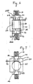
- Fig. 7 shows a modification of the first embodiment.
- a cylindrical bore 60 is formed in the slider 22 and a cylindrical nut 62 meshed with the threaded shaft 16 is received in the bore 60.
- the size of the bore 60 is somewhat larger than that of the nut 62 by a degree corresponding to the clearance indicated by "l3".
- the "universal joint connection" is also provided between the threaded shaft 16 and the slider 22 and thus the above-mentioned advantageous phenomenon is effected.
- FIGs. 4 and 5 there is shown a second embodiment of the present invention.
- a geared cylindrical member 42 is disposed in the casing 8 through a cylindrical bearing 43, so that the member 42 is rotatable about an axis which is in parallel with the axis of the drive shaft 10 of the motor 11. That is, the cylindrical member 42 has at its generally middle part an external helical gear 41 meshed with the helical gear 13 driven by the motor 11.
- An upper part 42a of the cylindrical member 42 is formed at its diametrically opposed portions with aligned slots 44.
- a collar 46 with a threaded bore 45 is coaxially but partially disposed in the upper part 42a of the cylindrical member 42 with a lower half of an annular elastomeric member 48 disposed therebetween.
- the collar 46 has two radially extending arms 47 engaged with the slots 44 respectively.
- the coaxially mated upper halves of the collar 46 and annular elastomeric member 48 are rotatably disposed in a cylindrical bore 49 formed in the casing 8.
- a threaded upper part 50 of a carry bar 52 which extends in parallel with the axis of the drive shaft 10 of the motor 11.
- the thread of the part 50 is indicated by 50a.
- the carry bar 52 passes through the geared cylindrical member 42 and an opening 51 which is formed in the upper wall 49a of the bore 49.
- Designated by numeral 53 is a pivotal bearing member which is positioned at a lower part of the casing 8 to pivotally support or bear the carry bar 52.
- the bearing member 53 comprises an apertured core 53a through which the carry bar 52 slidably passes and a holder (no numeral) which is secured to the casing 8 and pivotally holds therein the core 53a. That is, the carry bar 52 is somewhat pivotal about a center of the bearing member 53 relative to the casing 8.
- the lower end of the carry bar 52 is connected to the spoiler proper 2. Due to the connection with the bracket 28 through the connecting pin 29, the carry bar 52 is prevented from rotation about its axis.
- the coupling 15, the helical gear 13, the geared cylindrical member 42 and the arms 47 constitute the transmission mechanism 19 by which the power of the drive shaft 10 of the motor 11 is transmitted to the internally threaded collar 46.
- a position sensing device identical to the device 40 of the first embodiment is employed for controlling operation of the motor 11 in response to the upward and downward movement of the carry bar 52.
- Such device is arranged between an enlarged head of the carry bar 52 and an inner wall of the casing 8.
- the essential parts, such as motor 11, the threaded shaft 16 (in case of the first embodiment) and the carry bar 25 or 52 are arranged in parallel with one another. This parallel arrangement brings about a compact construction of the air spoiler retracting device.
Landscapes
- Engineering & Computer Science (AREA)
- Chemical & Material Sciences (AREA)
- Combustion & Propulsion (AREA)
- Transportation (AREA)
- Mechanical Engineering (AREA)
- Power-Operated Mechanisms For Wings (AREA)
- Transmission Devices (AREA)
Applications Claiming Priority (4)
| Application Number | Priority Date | Filing Date | Title |
|---|---|---|---|
| JP50617/88 | 1988-03-05 | ||
| JP5061788A JPH01226480A (ja) | 1988-03-05 | 1988-03-05 | エアスポイラー昇降装置 |
| JP37197/88U | 1988-03-23 | ||
| JP1988037197U JPH0642942Y2 (ja) | 1988-03-23 | 1988-03-23 | フロントスポイラーにおける昇降装置 |
Publications (3)
| Publication Number | Publication Date |
|---|---|
| EP0332084A2 true EP0332084A2 (fr) | 1989-09-13 |
| EP0332084A3 EP0332084A3 (en) | 1990-05-16 |
| EP0332084B1 EP0332084B1 (fr) | 1993-06-23 |
Family
ID=26376302
Family Applications (1)
| Application Number | Title | Priority Date | Filing Date |
|---|---|---|---|
| EP89103789A Expired - Lifetime EP0332084B1 (fr) | 1988-03-05 | 1989-03-03 | Dispositif de rétraction d'un volet aérodynamique |
Country Status (3)
| Country | Link |
|---|---|
| US (1) | US4902067A (fr) |
| EP (1) | EP0332084B1 (fr) |
| DE (1) | DE68907236T2 (fr) |
Cited By (2)
| Publication number | Priority date | Publication date | Assignee | Title |
|---|---|---|---|---|
| US7087726B2 (en) | 2001-02-22 | 2006-08-08 | Genentech, Inc. | Anti-interferon-α antibodies |
| GB2512477A (en) * | 2014-02-20 | 2014-10-01 | Daimler Ag | Bumper assembly for a commercial vehicle |
Families Citing this family (19)
| Publication number | Priority date | Publication date | Assignee | Title |
|---|---|---|---|---|
| JP2527818Y2 (ja) * | 1992-09-08 | 1997-03-05 | 株式会社大井製作所 | 車両用フロントエアスポイラー装置 |
| US6209935B1 (en) * | 1999-07-23 | 2001-04-03 | Daimlerchrysler Corporation | Front bumper adjustable fascia |
| WO2004073961A2 (fr) | 2003-02-18 | 2004-09-02 | Daimlerchrysler Ag | Particules de poudre revetues destinees a la production de corps tridimensionnels au moyen de procedes de constitution de couches |
| US7059664B2 (en) | 2003-12-04 | 2006-06-13 | General Motors Corporation | Airflow control devices based on active materials |
| US7118652B2 (en) * | 2003-12-04 | 2006-10-10 | General Motors Corporation | Airflow control devices based on active materials |
| US6979050B2 (en) * | 2003-12-04 | 2005-12-27 | General Motors Corporation | Airflow control devices based on active materials |
| US20050212310A1 (en) * | 2004-03-24 | 2005-09-29 | Viriyapanthu Paul Y | Device for protecting the front chin spoiler of an automobile |
| US7854467B2 (en) * | 2004-11-05 | 2010-12-21 | General Motors Corporation | Airflow control devices based on active materials |
| US7762615B2 (en) * | 2005-04-21 | 2010-07-27 | Roderick Dayton | Vehicle air dam system |
| US7686382B2 (en) * | 2005-10-12 | 2010-03-30 | Gm Global Technology Operations, Inc. | Reversibly deployable air dam |
| CA2642163C (fr) * | 2008-11-12 | 2010-08-17 | Roderick M. Dayton | Systeme permettant de diminuer la trainee aerodynamique sur des vehicules |
| DE102009034906A1 (de) * | 2009-07-28 | 2011-02-03 | GM Global Technology Operations, Inc., Detroit | Vorderteil für eine Kraftfahrzeugkarosserie |
| CA2795076C (fr) | 2011-11-10 | 2017-01-10 | Roderick M. Dayton | Systeme de reduction de la trainee aerodynamique |
| DE102011088608A1 (de) * | 2011-12-14 | 2013-06-20 | Bayerische Motoren Werke Aktiengesellschaft | Begrenzt drehende Welle mit Dichtung |
| US8702152B1 (en) * | 2013-01-11 | 2014-04-22 | Ford Global Technologies, Llc | Deployable front air dam |
| FR3031150B1 (fr) * | 2014-12-26 | 2018-05-11 | Compagnie Plastic Omnium | Organe de debrayage pour volet aerodynamique retractable de vehicule automobile |
| US10272958B2 (en) | 2015-06-07 | 2019-04-30 | RennKit LLC | Spoiler wing extension and retraction system |
| CN110114260A (zh) * | 2017-11-30 | 2019-08-09 | 沈国忠 | 用于汽车部件移动的汽车系统 |
| DE102020105085B4 (de) | 2020-02-27 | 2024-01-25 | Dr. Ing. H.C. F. Porsche Aktiengesellschaft | Adaptives Frontleitelement für ein Kraftfahrzeug |
Family Cites Families (10)
| Publication number | Priority date | Publication date | Assignee | Title |
|---|---|---|---|---|
| US4131308A (en) * | 1978-01-09 | 1978-12-26 | Ford Motor Company | Self-deploying chin spoiler for a vehicle |
| DE7906193U1 (de) * | 1978-03-24 | 1979-05-31 | Ford-Werke Ag, 5000 Koeln | Kraftfahrzeug-karosserie |
| JPS5751581A (en) * | 1980-09-08 | 1982-03-26 | Aisin Seiki Co Ltd | Air balancing panel |
| JPS58191672A (ja) * | 1982-05-06 | 1983-11-08 | Aisin Seiki Co Ltd | エアバランスパネル昇降装置 |
| IT1153678B (it) * | 1982-12-10 | 1987-01-14 | Alfa Romeo Spa | Spoiler a posizionamento automatico per un autoveicolo |
| JPS59156875A (ja) * | 1983-02-25 | 1984-09-06 | Mitsubishi Motors Corp | エアダム |
| JPS61222875A (ja) * | 1985-03-29 | 1986-10-03 | Oi Seisakusho Co Ltd | スポイラ−装置 |
| DE3542376A1 (de) * | 1985-11-30 | 1987-06-04 | Porsche Ag | Kraftfahrzeug mit einem benachbart einer fahrbahn verlaufenden bugendteil |
| DE3613302A1 (de) * | 1986-04-19 | 1987-10-29 | Daimler Benz Ag | Bugverkleidung fuer kraftwagen |
| JP2641425B2 (ja) * | 1986-05-16 | 1997-08-13 | 株式会社 大井製作所 | フロントスポイラ装置 |
-
1989
- 1989-03-03 US US07/318,568 patent/US4902067A/en not_active Expired - Fee Related
- 1989-03-03 EP EP89103789A patent/EP0332084B1/fr not_active Expired - Lifetime
- 1989-03-03 DE DE89103789T patent/DE68907236T2/de not_active Expired - Fee Related
Cited By (6)
| Publication number | Priority date | Publication date | Assignee | Title |
|---|---|---|---|---|
| US7087726B2 (en) | 2001-02-22 | 2006-08-08 | Genentech, Inc. | Anti-interferon-α antibodies |
| US7582445B2 (en) | 2001-02-22 | 2009-09-01 | Genentech, Inc. | Anti-interferon-α antibodies |
| US7910707B2 (en) | 2001-02-22 | 2011-03-22 | Genentech, Inc. | Anti-interferon-α antibodies |
| US8349331B2 (en) | 2001-02-22 | 2013-01-08 | Genentech, Inc. | Anti-interferon-α antibodies |
| US8557967B2 (en) | 2001-02-22 | 2013-10-15 | Genentech, Inc. | Anti-interferon-α antibodies |
| GB2512477A (en) * | 2014-02-20 | 2014-10-01 | Daimler Ag | Bumper assembly for a commercial vehicle |
Also Published As
| Publication number | Publication date |
|---|---|
| DE68907236T2 (de) | 1993-10-07 |
| US4902067A (en) | 1990-02-20 |
| EP0332084B1 (fr) | 1993-06-23 |
| DE68907236D1 (de) | 1993-07-29 |
| EP0332084A3 (en) | 1990-05-16 |
Similar Documents
| Publication | Publication Date | Title |
|---|---|---|
| US4902067A (en) | Air spoiler retracting device | |
| US7159904B2 (en) | Steering column for a motor vehicle | |
| EP0291087B1 (fr) | Commande de direction automatique des roues | |
| US12297685B2 (en) | Powered door unit with improved mounting arrangement | |
| US5520416A (en) | Power tilt, telescoping and internally collapsible steering column | |
| EP0107716B1 (fr) | Assemblage de charniere motorise | |
| US4609265A (en) | Rearview mirror actuating device | |
| DE4036451A1 (de) | Motorbetriebener, einschwenkbarer aussenspiegel fuer fahrzeuge | |
| EP0289266A2 (fr) | Rétroviseur avec dispositif de montage du miroir comportant une articulation bi-axiale montée intégralement | |
| ES2014401B3 (es) | Espejo exterior giratorio con telemando para vehiculos industriales | |
| JPH0579546B2 (fr) | ||
| KR920006485B1 (ko) | 직접구동형 다관절 로보트 | |
| CN119017426B (zh) | 一种机器人二自由度头部关节 | |
| EP0503084B1 (fr) | Robot industriel comportant un dispositif de commande multiple | |
| EP0368405A2 (fr) | Construction de toit ouvrant à commande électrique pour un véhicule | |
| US5309599A (en) | Wiping device for windows of power vehicles | |
| EP0505134A1 (fr) | Charnière motorisée, ouvrable, fermable, blocable et déblocable | |
| US5926331A (en) | Power pack for controlling the angular position of a vehicle rearview mirror | |
| JPH1084651A (ja) | 電動シリンダ | |
| JPH0742217Y2 (ja) | 電動アクチュエータ | |
| JPH0628374Y2 (ja) | 電気式パワ−ステアリング装置 | |
| JPH0743909Y2 (ja) | 開閉器 | |
| JPH01205987A (ja) | 関節機構 | |
| JP2578758Y2 (ja) | 電動式パワーステアリング装置 | |
| JPH088942Y2 (ja) | テレスコピックステアリング装置 |
Legal Events
| Date | Code | Title | Description |
|---|---|---|---|
| PUAI | Public reference made under article 153(3) epc to a published international application that has entered the european phase |
Free format text: ORIGINAL CODE: 0009012 |
|
| 17P | Request for examination filed |
Effective date: 19890303 |
|
| AK | Designated contracting states |
Kind code of ref document: A2 Designated state(s): DE FR GB |
|
| PUAL | Search report despatched |
Free format text: ORIGINAL CODE: 0009013 |
|
| AK | Designated contracting states |
Kind code of ref document: A3 Designated state(s): DE FR GB |
|
| 17Q | First examination report despatched |
Effective date: 19910912 |
|
| GRAA | (expected) grant |
Free format text: ORIGINAL CODE: 0009210 |
|
| AK | Designated contracting states |
Kind code of ref document: B1 Designated state(s): DE FR GB |
|
| REF | Corresponds to: |
Ref document number: 68907236 Country of ref document: DE Date of ref document: 19930729 |
|
| ET | Fr: translation filed | ||
| PLBE | No opposition filed within time limit |
Free format text: ORIGINAL CODE: 0009261 |
|
| STAA | Information on the status of an ep patent application or granted ep patent |
Free format text: STATUS: NO OPPOSITION FILED WITHIN TIME LIMIT |
|
| 26N | No opposition filed | ||
| PGFP | Annual fee paid to national office [announced via postgrant information from national office to epo] |
Ref country code: GB Payment date: 19980223 Year of fee payment: 10 |
|
| PGFP | Annual fee paid to national office [announced via postgrant information from national office to epo] |
Ref country code: DE Payment date: 19980306 Year of fee payment: 10 |
|
| PGFP | Annual fee paid to national office [announced via postgrant information from national office to epo] |
Ref country code: FR Payment date: 19980310 Year of fee payment: 10 |
|
| PG25 | Lapsed in a contracting state [announced via postgrant information from national office to epo] |
Ref country code: GB Free format text: LAPSE BECAUSE OF NON-PAYMENT OF DUE FEES Effective date: 19990303 |
|
| GBPC | Gb: european patent ceased through non-payment of renewal fee |
Effective date: 19990303 |
|
| PG25 | Lapsed in a contracting state [announced via postgrant information from national office to epo] |
Ref country code: FR Free format text: LAPSE BECAUSE OF NON-PAYMENT OF DUE FEES Effective date: 19991130 |
|
| REG | Reference to a national code |
Ref country code: FR Ref legal event code: ST |
|
| PG25 | Lapsed in a contracting state [announced via postgrant information from national office to epo] |
Ref country code: DE Free format text: LAPSE BECAUSE OF NON-PAYMENT OF DUE FEES Effective date: 20000101 |