EP0331887A2 - Auf eine Turbogeneratorwelle gekuppelter Hilfsgenerator, der über einen kurzen Zeitraum elektrische Energie für das Notinjektionskühlsystem erzeugt - Google Patents
Auf eine Turbogeneratorwelle gekuppelter Hilfsgenerator, der über einen kurzen Zeitraum elektrische Energie für das Notinjektionskühlsystem erzeugt Download PDFInfo
- Publication number
- EP0331887A2 EP0331887A2 EP89101106A EP89101106A EP0331887A2 EP 0331887 A2 EP0331887 A2 EP 0331887A2 EP 89101106 A EP89101106 A EP 89101106A EP 89101106 A EP89101106 A EP 89101106A EP 0331887 A2 EP0331887 A2 EP 0331887A2
- Authority
- EP
- European Patent Office
- Prior art keywords
- reactor
- coolant
- generator
- pump
- turbine
- Prior art date
- Legal status (The legal status is an assumption and is not a legal conclusion. Google has not performed a legal analysis and makes no representation as to the accuracy of the status listed.)
- Withdrawn
Links
- 239000002826 coolant Substances 0.000 title claims abstract description 122
- 238000002347 injection Methods 0.000 title claims abstract description 55
- 239000007924 injection Substances 0.000 title claims abstract description 55
- XLYOFNOQVPJJNP-UHFFFAOYSA-N water Substances O XLYOFNOQVPJJNP-UHFFFAOYSA-N 0.000 claims abstract description 49
- 238000009835 boiling Methods 0.000 claims abstract description 18
- 238000001816 cooling Methods 0.000 claims description 28
- 238000000034 method Methods 0.000 claims description 4
- 230000008569 process Effects 0.000 claims description 4
- 230000004087 circulation Effects 0.000 claims description 2
- 230000008878 coupling Effects 0.000 claims 3
- 238000010168 coupling process Methods 0.000 claims 3
- 238000005859 coupling reaction Methods 0.000 claims 3
- 238000010438 heat treatment Methods 0.000 claims 1
- 230000003405 preventing effect Effects 0.000 claims 1
- 229940090044 injection Drugs 0.000 description 30
- 230000001629 suppression Effects 0.000 description 20
- 238000013461 design Methods 0.000 description 16
- 238000005086 pumping Methods 0.000 description 15
- 238000013022 venting Methods 0.000 description 8
- 230000005484 gravity Effects 0.000 description 6
- 230000009467 reduction Effects 0.000 description 6
- 238000012546 transfer Methods 0.000 description 5
- 238000010586 diagram Methods 0.000 description 4
- 238000004401 flow injection analysis Methods 0.000 description 4
- 239000000446 fuel Substances 0.000 description 3
- 230000020169 heat generation Effects 0.000 description 3
- 230000007774 longterm Effects 0.000 description 3
- 230000008901 benefit Effects 0.000 description 2
- 230000000875 corresponding effect Effects 0.000 description 2
- 230000000694 effects Effects 0.000 description 2
- 230000004992 fission Effects 0.000 description 2
- 230000001052 transient effect Effects 0.000 description 2
- 238000011144 upstream manufacturing Methods 0.000 description 2
- 208000031501 Emergencies Diseases 0.000 description 1
- 208000036366 Sensation of pressure Diseases 0.000 description 1
- 230000009471 action Effects 0.000 description 1
- 230000002730 additional effect Effects 0.000 description 1
- 238000013459 approach Methods 0.000 description 1
- 230000000712 assembly Effects 0.000 description 1
- 238000000429 assembly Methods 0.000 description 1
- 230000033228 biological regulation Effects 0.000 description 1
- 239000000498 cooling water Substances 0.000 description 1
- 235000019628 coolness Nutrition 0.000 description 1
- 230000007423 decrease Effects 0.000 description 1
- 238000001704 evaporation Methods 0.000 description 1
- 230000008020 evaporation Effects 0.000 description 1
- 239000012530 fluid Substances 0.000 description 1
- 230000002706 hydrostatic effect Effects 0.000 description 1
- 208000015181 infectious disease Diseases 0.000 description 1
- 230000000977 initiatory effect Effects 0.000 description 1
- 238000012423 maintenance Methods 0.000 description 1
- 238000005259 measurement Methods 0.000 description 1
- 238000012986 modification Methods 0.000 description 1
- 230000004048 modification Effects 0.000 description 1
- 239000003758 nuclear fuel Substances 0.000 description 1
- 238000005457 optimization Methods 0.000 description 1
- 238000013021 overheating Methods 0.000 description 1
- 238000010248 power generation Methods 0.000 description 1
- 239000000047 product Substances 0.000 description 1
- 230000000750 progressive effect Effects 0.000 description 1
- 230000005258 radioactive decay Effects 0.000 description 1
- 230000002441 reversible effect Effects 0.000 description 1
- 230000004905 short-term response Effects 0.000 description 1
- 238000004513 sizing Methods 0.000 description 1
- 238000009987 spinning Methods 0.000 description 1
- 238000003860 storage Methods 0.000 description 1
- 239000013589 supplement Substances 0.000 description 1
- 238000004804 winding Methods 0.000 description 1
Images


Classifications
-
- G—PHYSICS
- G21—NUCLEAR PHYSICS; NUCLEAR ENGINEERING
- G21C—NUCLEAR REACTORS
- G21C15/00—Cooling arrangements within the pressure vessel containing the core; Selection of specific coolants
- G21C15/18—Emergency cooling arrangements; Removing shut-down heat
-
- G—PHYSICS
- G21—NUCLEAR PHYSICS; NUCLEAR ENGINEERING
- G21C—NUCLEAR REACTORS
- G21C15/00—Cooling arrangements within the pressure vessel containing the core; Selection of specific coolants
- G21C15/18—Emergency cooling arrangements; Removing shut-down heat
- G21C15/182—Emergency cooling arrangements; Removing shut-down heat comprising powered means, e.g. pumps
- G21C15/185—Emergency cooling arrangements; Removing shut-down heat comprising powered means, e.g. pumps using energy stored in reactor system
-
- Y—GENERAL TAGGING OF NEW TECHNOLOGICAL DEVELOPMENTS; GENERAL TAGGING OF CROSS-SECTIONAL TECHNOLOGIES SPANNING OVER SEVERAL SECTIONS OF THE IPC; TECHNICAL SUBJECTS COVERED BY FORMER USPC CROSS-REFERENCE ART COLLECTIONS [XRACs] AND DIGESTS
- Y02—TECHNOLOGIES OR APPLICATIONS FOR MITIGATION OR ADAPTATION AGAINST CLIMATE CHANGE
- Y02E—REDUCTION OF GREENHOUSE GAS [GHG] EMISSIONS, RELATED TO ENERGY GENERATION, TRANSMISSION OR DISTRIBUTION
- Y02E30/00—Energy generation of nuclear origin
- Y02E30/30—Nuclear fission reactors
Definitions
- the present invention relates to emergency core cooling system (ECCS) networks for nuclear power reactors. More particularly, the invention is preferably designed to compliment advanced boiling water reactor (BWR) designs known as simplified boiling water reactors (SBWRs). Under the invention as applied to SBWRs, reactor coolant inventory is replenished, in a backup mode to the safety-grade emergency core cooling system, at an early point following a loss-of-coolant accident. The spindown energy of the main turbine-generator is used to drive selected pumps such as the condensate pumps to achieve desired initial injections of emergency coolant into the reactor.
- BWR advanced boiling water reactor
- SBWRs simplified boiling water reactors
- the feedwater supply system for many conventional boiling water reactors and especially for simplified boiling water reactors is a conventional yet simplified system, characterized by two stages of pumping. These pumping stages raise the feedwater from the below-atmospheric pressures at the source of the feedwater flow--namely, the condenser hotwell--to the pressures needed for injection into the BWR feedwater spargers positioned inside the reactor.
- the first or lowermost pumping stage customarily termed the “condensate” stage, contains condensate pumps having pump discharge pressures, at design flow, of approximately 500 psig, with shutoff heads of approximately 600 psig.
- the second or uppermost pumping stage customarily termed the "feedwater” stage, contains feedwater pumps capable of increasing the feedwater supply pressure to approximately 1250 psig.
- the pumping burden at both stages, is commonly shared by redundant pumps.
- a configuration featuring three condensate pumps (and also three feedwater pumps) each having 50% rated flow capacity is one attractive configuration.
- One pump from each stage may be held in a standby mode, to be brought into service in case an operational pump requires shutdown for any reason.
- these pump units are motor-driven by power from the main station power supply, with the feedwater pumps having adjustable-speed drives to provide feedwater regulation to the reactor.
- the reactor must be supplied with additional coolant and cooled-- that is, the reactor coolant level must be maintained high enough to cover all of the reactor nuclear fuel assemblies.
- additional coolant must be supplied by reliable emergency cooling systems which draw power from reliable alternative sources.
- Loss-of-coolant inventory conditions may occur because of a pipe break (i.e., a LOCA), loss of feedwater supply, or because a safety-relief valve has stuck-open and failed to reclose following a transient. Coolant must be maintained, or must be rapidly replenished following its loss during such accident conditions, to keep the reactor core supplied with coolant to counteract core decay heat generation.
- ECCS electronic commerce core cooling network
- coolant inventory is depleted within the reactor through processes of boiling and evaporation as the hot reactor coolant continues to receive decay heat from the core.
- the replenishment rates may be large immediately following an accident. Thereafter, however, replenishment rates diminish as time goes on and the decay heat generation rate decreases.
- replenishment of coolant must continue until the break can be isolated and normal coolant inventory level reestablished inside the reactor. For certain accidents, replenishment must continue until the region of the containment immediately outside the reactor pressure vessel can be flooded to an elevation above the top of the core active fuel level or the break, whichever is higher.
- BWR ECCS networks for example the BWR/3 through the BWR/6 model BWR designs by GE Nuclear Energy, utilize a combination of pumping systems and power supplies to pump coolant into the reactor following any loss-of-coolant inventory condition.
- Water is typically used as the emergency coolant for BWRs.
- the source of water can be any available quantity of water within the power station or its premises.
- the BWR/3 through BWR/6 reactors typically draw emergency coolant from a containment suppression pool.
- This suppression pool provides water which is assured, is available in large amounts, and is generally of a quality that is not particularly harmful to the reactor vessel or the nuclear steam supply system piping or equipment.
- the conventional BWR designs have several drawbacks relating to emergency core cooling resulting from the extremely long pump duty cycles needed to meet coolant replenishment requirements.
- both the pumps and the piping networks as well as the power supplies that power the ECCS have heretofore been costly dedicated systems having high reliability ratings.
- Such high reliability ECCS design often is achievable only by providing redundant components or even redundant pumping loops. Such redundancy in systems results in significant cost increases for the power station.
- main system generator As a source of power for ECCS pumps during some LOCAs.
- electrical power from the main generator is hypothesized to be unavailable.
- the main generator itself may be in a shorted condition (e.g., shorted windings), or the main generator may otherwise have been taken offline during the LOCA.
- SBWRs--position the suppression pool previously discussed at a high elevation in the containment vessel relative to the core top-of-active-fuel (TAF) elevation.
- TAF core top-of-active-fuel
- This elevation of the suppression pool overcomes the long-term need for continuous pumped coolant injection into the reactor.
- the suppression pool is connected via a plurality of pipes directly to the reactor, with valves--typically check valves--that prevent the discharge of high-pressure reactor coolant into the suppression pool during routine reactor power generation.
- This system of pipes and valves is termed a "gravity-driven cooling system (GDCS)", and along with associated venting systems, represents the entire ECCS network for certain SBWRs.
- GDCS gravitation-driven cooling system
- the SBWR reactor is promptly depressurized to the suppression pool pressure level using a venting system.
- a low pressure level such as 30 psig
- the hydrostatic head created by the elevated suppression pool initiates flow of suppression pool water into the reactor.
- the suppression pool includes sufficient water such that during a LOCA, both the reactor as well as the region of the containment external to the reactor (the "drywell") can be flooded to a level moderately higher than the TAF level.
- a design goal for SBWR is not only to avoid exceeding core temperature limits during the course of any design basis accident, but also to provide ample margin against such occurrence. This assured margin is attained by specifying no core uncovery condition shall occur, even briefly, during such accidents. However, any added systems that provide this margin are not required to meet safety-grade design criteria, and these systems are taken as backups to, but not part of the ECCS network itself.
- added or backup systems that are not required to be part of the ECCS network is that they can be designed to less-stringent criteria, which translates to less expense. At the same time these added or backup systems provide important enhanced investment protection to the power station because they further reduce the risk of core damage given an accident.
- the SBWR reactor vessel is designed to contain excess water, relative to conventional BWRs. This extra water is contained in a zone starting with the TAF and extending up to the water level at which reactor depressurization signals are initiated (termed "Level-1").
- Level-1 the water level at which reactor depressurization signals are initiated.
- the zone between TAF and Level-1 in such SBWR reactor designs contains an amount of water corresponding to approximately one minute of rated feedwater flow injection. This amount is substantially larger than in conventional BWR designs which rely on long term ECCS pumped water injection into the reactor during and following reactor depressurization.
- an improved, reliable, low-cost electrical power supply and coolant injection system useful in such applications as the ECCS network for SBWRs.
- the invention uses one or more dedicated auxiliary generators, of small size and generating capacity relative to the size/capacity of the power station's main generator, which are direct-coupled mechanically to the main turbine-generator.
- electrical power derived from these auxiliary generators is the preferred power supply to the station condensate pump-motors.
- these condensate pumps remain connected to their respective auxiliary generators to maintain pumping of condensate into the reactor. This continued pumping of condensate begins the emergency introduction of condensate from the moment when the depressurized condition inside the reactor exceeds the current shutoff head capacity corresponding to the condensate pump motor speed.
- the generators are used to supply the electrical power for the aforesaid loads--for example, condensate pumps--during normal station operation.
- loads--for example, condensate pumps--during normal station operation for example, condensate pumps--during normal station operation.
- no start-up of alternate power sources is required to effect continuation of function, or switch-over of function to ECCS service.
- the invention thus eliminates one of the principal causes for unreliability for conventional ECCS networks--namely, the start-up of the diesel-generator.
- This configuration of condensate pumps powered by auxiliary generators (preferred source) also avoids the cost of providing separate dedicated emergency injection pumps and diesel generators. Due to provision of emergency coolant replenishment according to the invention, the cost of providing extra volume (described as TAF-to Level-1 volume) inside the reactor vessel and the suppression pool is additionally minimized.
- the short term power supply permits slow-coastdown of upper-stage feedwater pumps during transients involving loss-of-offsite-power.
- the shaft-coupled auxiliary generator and the pump-motors to which they are connected are designed to non-safety-grade criteria. In an alternative embodiment, these components are all designed as safety-grade components.
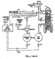
- FIG. 1 is a simplified block diagram for a simplified boiling water reactor 2 of prior art configuration.
- Reactor 2 includes a reactor pressure vessel 4 which has disposed therein a reactor core 6. The reactor core is covered by cooling water 8 which is supplied and circulated during normal operation. Normal operation can be simply summarized.
- steam from the reactor vessel 4 is input to turbine 24.
- Turbine 24 is coupled to generator 30 through the main rotating shaft 32 of turbine 24.
- the power output of generator 30 is coupled to the main station power supply 50.
- Condensate discharged from condensate pump 18 is fed to the suction of feed pump 16.
- Feed pump 16 elevates the head of the feedwater to exceed reactor vessel pressure and supplies feedwater through feedwater line 38 back to the reactor vessel 4, thereby completing the steam cycle.
- reactor vessel When a loss-of-coolant inventory accident occurs, the reactor vessel is depressurized through depressurization valve 90 and vent line 92 to suppression pool 10. When depressurization has progressed to an appropriate degree, reactor 2 becomes cooled by the gravity injection of suppression pool coolant through check valve 94.
- Backup cooling is conventionally provided using power from a main power supply 50 to power feedwater (cooling) system 200.
- the emergency power may be provided from either the main coupled generator 30, the grid, or from diesel generators (not shown).
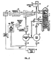
- FIG. 2 is an illustration of an improved emergency core cooling system according to one embodiment of the invention.
- FIG. 2 shows the conventional prior art boiling water reactor 2 having the emergency core cooling system according to one embodiment of the invention.
- FIG. 2 shows the conventional prior art boiling water reactor 2 having the emergency core cooling system featuring a low pressure coolant infection capability.
- a steam output from the turbine-generator 24 inputs to condenser 44.
- a condensate storage tank 41 supplements the inventory of condensate within the condenser 44 to replenish water inventory within condenser 44 whenever reactor steam supply becomes isolated.
- Output of condenser 44 is coupled to condensate pump 18.
- the output of condensate pump 18 has two separate destinations. The first conventional destination is to the suction of feed pump 16. The second destination is to the upstream side of a check valve 120 on a bypass line 22.
- the output of check valve 120 is coupled to the interior of reactor vessel 4.
- the bypass line 22 and check valve 120 may be configured to tie into feedwater line 38 or into a dedicated injection inlet to vessel 4.
- an auxiliary generator 34 is coupled to a main shaft of the coupled main generator 30 and turbine 24.
- the output of auxiliary generator 34 is coupled to an input to power supply 36.
- power supply 36 is dedicated to driving pump motor 28.
- This condensate pump 18 has a dedicated power supply from generator 34.
- Pump motor 28 drives condensate pump 18 using power generated by auxiliary generator 34.
- Power supply 36 is normally directly connected to motor 28 without any intervening switching or bus transfer required.
- Auxiliary generator 34 provides normal short-term-response power for motor 28 when condensate pump 18 is used during normal initial core cooling.
- Auxiliary generator 34 converts the rotational energy of main turbine and main coupled generator into electric power, including converting the spindown momentum during loss-of-coolant inventory accidents.
- FIG. 3 is a coolant flow of an alternative embodiment of the invention.
- Low pressure injection pump 48 intakes coolant derived from condenser 44 and discharges the coolant through injection line 23 and injection check valve 21 into reactor vessel 4. It is required that low pressure injection motor 58 and pump 48 be signalled and brought on line responsive to conventional prior art reactor water level indicators.
- Auxiliary generator 34 provides power to motor 58 driving low pressure injection pump 48. While this alternative embodiment represents potential cost increases resulting from the addition of a new pump/motor unit and its connecting piping, there are potential major net cost reductions to the resultant overall system depending on the sizing of pump/motor unit 48/58.
- a bypass low pressure coolant injection (LPCI) line 23 is provided.
- Line 23 incorporates a normally-closed LPCI flow injection valve 21 located upstream of an LPCI injection nozzle.
- LPCI injection nozzle is positioned on the reactor vessel 4 and communicated to the discharge side of LPCI pump 48.
- Reactor 4 through conventional prior art sensors senses a loss-of-coolant inventory condition and begins depressurization through sequentially-opened depressurization valves 90 once the water level inside the reactor 4 reaches the Level-1 level.
- the bypass line injection valve 21 opens to admit pumped condensate to the reactor.
- the LPCI flow tends to increase--this effect being caused by the characteristic of centrifugal pumps to provide increased volume throughout as pump back-pressure decreases--but may (depending on LPCI motor controls) be partially offset by the reduction in rotational speed (referred to as coastdown or spindown) of the main turbine-generator as a consequence both of turbine-generator bearings and windage losses as well as energy removed for pumping.
- coastdown or spindown the reduction in rotational speed of the main turbine-generator as a consequence both of turbine-generator bearings and windage losses as well as energy removed for pumping.
- the main turbine-generator would supply power to the main station (site) power supply.
- the site power supply 50 would supply power to feed pump 16 and to a condensate pump 18 during normal operations.
- grid power sources and/or non-safety-grade diesel generators, as available, are coupled via bus transfer to the feed pump and to the condensate pump to provide alternate power for the requisite pumping during a loss-of-coolant inventory accident.
- the power supply for backup emergency cooling according to the disclosed invention is inherently more reliable over the duration of power supply need, because of the avoidance of requiring start-up of diesel generators and/or because of the avoidance of bus transfers from electrical buses that are subject to externally-caused power interruptions.
- the emergency coolant injection power supply for the low pressure coolant injection capability is furnished by dedicated, unswitched normal and emergency power from auxiliary generator 34 to the condensate pump 18.
- the auxiliary generator 34 also can supply normal and emergency power to selected other emergency core cooling system loads 60.
- the feed pumps which draw substantial power (on the order of several megawatts) are fed from the site power supply 50 over normal lines to a power input to drive motor 26 of feed pump 16.
- feedwater is used to power the recirculation flow in a boiling water reactor--such as in the case of a feedwater-driven jet pump recirculation system BWR--the feature of having short-term continued feedwater injection capability is highly desirable.
- the invention brings about the capability of being able to maintain coolant forced circulation in such reactors over the short term of depressurization experienced in a loss of coolant accident.
- FIG. 4 is a graph that depicts the reactor depressurization curve for a conventional simplified boiling water reactor that uses a venting system together with a gravity-driven cooling system. This same graph also depicts improved system in accordance with the invention. This improved system uses a venting system, a gravity-driven system, and short term low pressure coolant injection capability to inject condensate into the reactor vessel during the depressurization phase, at the early part of a loss-of-coolant inventory accident.
- time t0 represents the time at which an event requiring emergency core cooling occurs.
- the pressure in the reactor vessel will be approximately 1000 psig at the point in time when venting is initiated.
- the reactor vessel would be depressurized down to about 30 psig over approximately a 10-12 minute interval using the venting system.
- FIG. 4 The improved performance of this invention is illustrated in FIG. 4 in broken lines.
- condensate is pumped back into the reactor vessel using the emergency power supply system and condensate (low pressure) pumps.
- Such introduction of condensate occurs when the reactor/injection vessel pressure reaches the shutoff head far the condensate (low pressure) pump which is around 600 psig.
- the reactor vessel can be depressurized down to 30 psig at some t2 which is several minutes earlier than for the conventional system.
- the water provided by the LPCI pump (per FIG. 3 embodiment) or by the condensate pump (per FIG. 2 embodiment) using the spindown energy of the turbine generator during the four-minute period provides reliable, low cost, short term emergency coolant. This coolant undergoes injection with considerable margin relative to the volumetric inventory between TAF and Level-1.
- each LPCI pump (condensate pump) is producing nominally 50% rated feedwater flow.
- the depressurization period necessary to bring the vessel pressure down to 30 psig, over which reactor inventory depletion occurs by venting coolant through the depressurization valves is limited to four minutes as compared to 10 to 12 minutes with no injection.
- the amount of required injection flow is thus seen to be small relative to the BWR/3 through the BWR/6 model BWR designs that require coolant flow injections uninterrupted for indefinitely long time periods. Since the integrated pumping energy demand over the period of interest--said to be no longer than five minutes even under worst-case event scenarios--is demonstrably small, the invention is able to use the spindown energy of the main turbine-generator as an assured, virtually cost free source of emergency power.
- the turbine-generator of the typical BWR power station typically requires no less than 40 minutes to spindown to speeds at which the turbine-generator turning gear cuts-in to maintain slow revolutions on the turbine-generator shaft.
- This coastdown is produced by the combination of frictional drag from bearings, plus windage losses by the turbine-generator blades spinning in the low pressure (typically 2-3 ins.Hg) maintained by the main condenser.
- the low pressure typically 2-3 ins.Hg
- approximately 1.5 MWe-equivalent drag is produced at the 1500 rpm (50 cycle)/1800 rpm (60 cycle) initial free-rotation speed.
- the energy extracted by the shaft-coupled auxiliary generator(s) and consumed by the electrically-coupled LPCI and/or condensate pumps amounts to the same order-of-magnitude rate as for the turbine-generator bearing and windage losses.
- the 4 or 5 minutes integrated energy drawn by the LPCI and/or condensate pumps can be seen to be modest relative to the integrated energy available from the turbine-generator coastdown.
- a properly sized flywheel can be added to the turbine-generator system to provide the additional rotational energy required.
- auxiliary generators can include opening or closing certain motor-operated valves, or providing power for forced injection of coolant from the elevated suppression pool into the reactor vessel to accelerate depressurization of the reactor vessel. It is also possible to conserve the useful energy of the short term power supply, for example, by not switching the LPCI pump on (in the FIG. 3 embodiment) until the reactor vessel pressure has fallen below the shutoff head for the LPCI pump. Further, it is also possible to use feedwater pumps and condensate pumps either in combination or in a staggered timing relationship depending on design constraints. It is also possible within the scope of the invention to use separate dedicated LPCI pumps and injection lines that tie into the normal condensate line.
- auxiliary generator it is also within the scope of the invention to couple power from the auxiliary generator to a main station transfer bus. It is possible to supply during normal operation the condensate pump with power derived directly from the main coupled generator feeding this main transfer bus. After occurrence of a loss-of-coolant inventory accident, the main bus could switch so that power would be provided from the auxiliary generators. This approach obviously lacks the higher reliability feature of those embodiments not requiring any switching.
Landscapes
- Physics & Mathematics (AREA)
- Engineering & Computer Science (AREA)
- Plasma & Fusion (AREA)
- General Engineering & Computer Science (AREA)
- High Energy & Nuclear Physics (AREA)
- Structure Of Emergency Protection For Nuclear Reactors (AREA)
- Engine Equipment That Uses Special Cycles (AREA)
- Structures Of Non-Positive Displacement Pumps (AREA)
Applications Claiming Priority (2)
| Application Number | Priority Date | Filing Date | Title |
|---|---|---|---|
| US155433 | 1988-02-12 | ||
| US07/155,433 US4818475A (en) | 1988-02-12 | 1988-02-12 | Turbine-generator shaft-coupled auxiliary generators supplying short-duration electrical loads for an emergency coolant injection system |
Publications (2)
| Publication Number | Publication Date |
|---|---|
| EP0331887A2 true EP0331887A2 (de) | 1989-09-13 |
| EP0331887A3 EP0331887A3 (de) | 1990-05-02 |
Family
ID=22555408
Family Applications (1)
| Application Number | Title | Priority Date | Filing Date |
|---|---|---|---|
| EP89101106A Withdrawn EP0331887A3 (de) | 1988-02-12 | 1989-01-23 | Auf eine Turbogeneratorwelle gekuppelter Hilfsgenerator, der über einen kurzen Zeitraum elektrische Energie für das Notinjektionskühlsystem erzeugt |
Country Status (3)
| Country | Link |
|---|---|
| US (1) | US4818475A (de) |
| EP (1) | EP0331887A3 (de) |
| JP (1) | JPH0718945B2 (de) |
Cited By (1)
| Publication number | Priority date | Publication date | Assignee | Title |
|---|---|---|---|---|
| CN113299417A (zh) * | 2021-05-25 | 2021-08-24 | 中国核动力研究设计院 | 核电厂停堆工况主泵运行时的安注触发方法和装置及系统 |
Families Citing this family (30)
| Publication number | Priority date | Publication date | Assignee | Title |
|---|---|---|---|---|
| US5120494A (en) * | 1990-07-10 | 1992-06-09 | General Electric Company | Reactor-core isolation cooling system with dedicated generator |
| US5108695A (en) * | 1991-02-25 | 1992-04-28 | Westinghouse Electric Corp. | Ventilating system for an emergency feedwater enclosure in a nuclear power plant |
| US5217682A (en) * | 1991-05-17 | 1993-06-08 | Atomic Energy Of Canada Limited | Passive indirect shutdown cooling system for nuclear reactors |
| US5169595A (en) * | 1991-09-03 | 1992-12-08 | General Electric Company | Reactor core isolation cooling system |
| US5426681A (en) * | 1994-01-04 | 1995-06-20 | General Electric Company | Boiling water reactor with combined active and passive safety systems |
| US6199382B1 (en) * | 1998-11-25 | 2001-03-13 | Penn State Research Foundation | Dynamic condensate system |
| JP2001208485A (ja) * | 2000-01-26 | 2001-08-03 | Honda Motor Co Ltd | 凝縮器 |
| KR20020037104A (ko) * | 2000-11-13 | 2002-05-18 | 장인순 | 이차계통을 이용한 주기기 냉각 방법과 장치 |
| US6627815B1 (en) * | 2002-10-07 | 2003-09-30 | Joel D. Ebersole | All-in-one junction box for electrical hook-up of furnaces and ancillary fixed appliances |
| JP4381153B2 (ja) * | 2004-01-14 | 2009-12-09 | 株式会社東芝 | 非常用炉心冷却系および原子力プラント |
| US11569001B2 (en) | 2008-04-29 | 2023-01-31 | Holtec International | Autonomous self-powered system for removing thermal energy from pools of liquid heated by radioactive materials |
| US9691507B2 (en) | 2009-04-13 | 2017-06-27 | Terrapower, Llc | Method and system for the thermoelectric conversion of nuclear reactor generated heat |
| US9892807B2 (en) | 2009-04-13 | 2018-02-13 | Terrapower, Llc | Method, system, and apparatus for selectively transferring thermoelectrically generated electric power to nuclear reactor operation systems |
| US9767934B2 (en) | 2009-04-13 | 2017-09-19 | Terrapower, Llc | Method, system, and apparatus for the thermoelectric conversion of gas cooled nuclear reactor generated heat |
| US9799417B2 (en) * | 2009-04-13 | 2017-10-24 | Terrapower, Llc | Method and system for the thermoelectric conversion of nuclear reactor generated heat |
| JP5675134B2 (ja) * | 2010-03-18 | 2015-02-25 | 三菱重工業株式会社 | 非常用システム |
| WO2012145406A2 (en) * | 2011-04-18 | 2012-10-26 | Holtec International, Inc. | Autonomous self-powered system for removing thermal energy from pools of liquid heated by radioactive materials, and methods of the same |
| US11504814B2 (en) | 2011-04-25 | 2022-11-22 | Holtec International | Air cooled condenser and related methods |
| WO2012149057A1 (en) | 2011-04-25 | 2012-11-01 | Holtec International, Inc. | Air-cooled heat exchanger and system and method of using the same to remove waste thermal energy from radioactive materials |
| JP2013019879A (ja) * | 2011-07-13 | 2013-01-31 | Gunji Haga | 自動停止源発の原子炉冷却方式 |
| US20130044851A1 (en) * | 2011-08-17 | 2013-02-21 | Westinghouse Electric Company Llc | Backup nuclear reactor auxiliary power using decay heat |
| KR101234570B1 (ko) * | 2011-09-19 | 2013-02-19 | 한국원자력연구원 | 냉각재 상실사고 완화가 가능한 일체형 원자로 및 그 완화방법 |
| US10311985B2 (en) * | 2011-11-04 | 2019-06-04 | Ge-Hitachi Nuclear Energy Americas Llc | Fault tolerant turbine speed control system |
| US9312035B2 (en) * | 2011-11-14 | 2016-04-12 | Westinghouse Electric Company Llc | Semi-portable emergency cooling system for removing decay heat from a nuclear reactor |
| US10529457B2 (en) | 2012-04-17 | 2020-01-07 | Bwxt Mpower, Inc. | Defense in depth safety paradigm for nuclear reactor |
| CN105026087A (zh) | 2012-12-03 | 2015-11-04 | 霍尔泰克国际股份有限公司 | 钎焊组合物及其用途 |
| US20150167550A1 (en) * | 2013-12-18 | 2015-06-18 | General Electric Company | System and method for processing gas streams |
| JP6454622B2 (ja) * | 2015-08-28 | 2019-01-16 | 日立Geニュークリア・エナジー株式会社 | 原子炉隔離時冷却装置 |
| US10883352B2 (en) * | 2016-08-12 | 2021-01-05 | Halliburton Energy Services, Inc. | Auxiliary electric power system for well stimulation operations |
| CN110514894B (zh) * | 2019-07-24 | 2021-05-11 | 中石化南京工程有限公司 | 一种基于漏电安全的电炉短网冷却水系统设计方法 |
Family Cites Families (4)
| Publication number | Priority date | Publication date | Assignee | Title |
|---|---|---|---|---|
| GB1133084A (en) * | 1965-09-17 | 1968-11-06 | English Electric Co Ltd | Power plants |
| GB1236538A (en) * | 1970-05-26 | 1971-06-23 | Hayward Tyler & Co Ltd | Improvements in power supply arrangements for coolant circulators of nuclear reactors |
| DE2606469B2 (de) * | 1976-02-18 | 1977-12-22 | Kraftwerk Union AG, 4330 Mülheim | Notspeisesystem zur kuehlung von kernreaktoranlagen |
| DE3330012A1 (de) * | 1983-08-19 | 1985-03-07 | Kraftwerk Union AG, 4330 Mülheim | Siedewasserreaktor |
-
1988
- 1988-02-12 US US07/155,433 patent/US4818475A/en not_active Expired - Fee Related
-
1989
- 1989-01-23 EP EP89101106A patent/EP0331887A3/de not_active Withdrawn
- 1989-02-10 JP JP1030116A patent/JPH0718945B2/ja not_active Expired - Lifetime
Cited By (1)
| Publication number | Priority date | Publication date | Assignee | Title |
|---|---|---|---|---|
| CN113299417A (zh) * | 2021-05-25 | 2021-08-24 | 中国核动力研究设计院 | 核电厂停堆工况主泵运行时的安注触发方法和装置及系统 |
Also Published As
| Publication number | Publication date |
|---|---|
| EP0331887A3 (de) | 1990-05-02 |
| JPH01267495A (ja) | 1989-10-25 |
| JPH0718945B2 (ja) | 1995-03-06 |
| US4818475A (en) | 1989-04-04 |
Similar Documents
| Publication | Publication Date | Title |
|---|---|---|
| US4818475A (en) | Turbine-generator shaft-coupled auxiliary generators supplying short-duration electrical loads for an emergency coolant injection system | |
| US5426681A (en) | Boiling water reactor with combined active and passive safety systems | |
| EP2642489A1 (de) | Notfallkühlsystem für einen reaktorkern und kernkraftwerk mit wassererhitzung | |
| EP0538400A1 (de) | Reaktor-spaltzonenisolationskühlsystem mit eigenem generator | |
| US20200072087A1 (en) | External reactor vessel cooling and electric power generation system | |
| US4278500A (en) | Pressurized water reactor | |
| US5428652A (en) | Secondary-side residual-heat removal system for pressurized-water nuclear reactors | |
| WO2011074544A1 (ja) | 原子炉の過渡緩和システム | |
| Matzie et al. | Design of the safe integral reactor | |
| EP0238079B1 (de) | Spaltzonennotkühlungsanlage | |
| EP0017685B1 (de) | Pumpenantriebseinrichtung für einen Flüssigmetallreaktor | |
| JP2859990B2 (ja) | 沸騰水型原子炉設備 | |
| CN214175702U (zh) | 用于非能动核电厂的蒸汽发生器非能动补水系统 | |
| Conway et al. | Simplified safety and containment systems for the IRIS reactor | |
| JPS6314001A (ja) | 蒸気発生器出力制御装置 | |
| JP2011185741A (ja) | 非常用炉心冷却系 | |
| JPH055318B2 (de) | ||
| Omoto et al. | ABWR evolution program | |
| JPH0567000B2 (de) | ||
| JPS6285889A (ja) | 原子炉冷却材再循環ポンプ速度の制御方法 | |
| Murase et al. | The development of the evolutionary BWR | |
| Frutschi et al. | Power generating plant with a gas-cooled nuclear reactor with closed gas circulation | |
| JPS5999008A (ja) | 蒸気発生プラントの制御方法 | |
| JPS61110096A (ja) | 原子炉水位制御方法 | |
| JPH07128491A (ja) | 自然循環型原子炉の全容量バイパスシステム制御装置 |
Legal Events
| Date | Code | Title | Description |
|---|---|---|---|
| PUAI | Public reference made under article 153(3) epc to a published international application that has entered the european phase |
Free format text: ORIGINAL CODE: 0009012 |
|
| AK | Designated contracting states |
Kind code of ref document: A2 Designated state(s): CH DE ES IT LI NL SE |
|
| PUAL | Search report despatched |
Free format text: ORIGINAL CODE: 0009013 |
|
| AK | Designated contracting states |
Kind code of ref document: A3 Designated state(s): CH DE ES IT LI NL SE |
|
| 17P | Request for examination filed |
Effective date: 19901026 |
|
| STAA | Information on the status of an ep patent application or granted ep patent |
Free format text: STATUS: THE APPLICATION IS DEEMED TO BE WITHDRAWN |
|
| 18D | Application deemed to be withdrawn |
Effective date: 19920801 |