EP0331847A2 - Mehrfachprojektionsfernsehempfänger - Google Patents
Mehrfachprojektionsfernsehempfänger Download PDFInfo
- Publication number
- EP0331847A2 EP0331847A2 EP88311630A EP88311630A EP0331847A2 EP 0331847 A2 EP0331847 A2 EP 0331847A2 EP 88311630 A EP88311630 A EP 88311630A EP 88311630 A EP88311630 A EP 88311630A EP 0331847 A2 EP0331847 A2 EP 0331847A2
- Authority
- EP
- European Patent Office
- Prior art keywords
- modules
- projection television
- television receiver
- couplers
- multiple projection
- Prior art date
- Legal status (The legal status is an assumption and is not a legal conclusion. Google has not performed a legal analysis and makes no representation as to the accuracy of the status listed.)
- Granted
Links
- 239000003086 colorant Substances 0.000 claims abstract description 7
- 230000008878 coupling Effects 0.000 claims description 12
- 238000010168 coupling process Methods 0.000 claims description 12
- 238000005859 coupling reaction Methods 0.000 claims description 12
- 230000000875 corresponding effect Effects 0.000 claims description 10
- 229910000831 Steel Inorganic materials 0.000 claims description 4
- 239000010959 steel Substances 0.000 claims description 4
- 238000003780 insertion Methods 0.000 description 7
- 230000037431 insertion Effects 0.000 description 7
- 230000003014 reinforcing effect Effects 0.000 description 5
- 230000003247 decreasing effect Effects 0.000 description 2
- 238000005286 illumination Methods 0.000 description 2
- 238000000034 method Methods 0.000 description 2
- XAGFODPZIPBFFR-UHFFFAOYSA-N aluminium Chemical compound [Al] XAGFODPZIPBFFR-UHFFFAOYSA-N 0.000 description 1
- 229910052782 aluminium Inorganic materials 0.000 description 1
- 238000010276 construction Methods 0.000 description 1
- 230000000694 effects Effects 0.000 description 1
Images




Classifications
-
- H—ELECTRICITY
- H04—ELECTRIC COMMUNICATION TECHNIQUE
- H04N—PICTORIAL COMMUNICATION, e.g. TELEVISION
- H04N9/00—Details of colour television systems
- H04N9/12—Picture reproducers
-
- H—ELECTRICITY
- H04—ELECTRIC COMMUNICATION TECHNIQUE
- H04N—PICTORIAL COMMUNICATION, e.g. TELEVISION
- H04N5/00—Details of television systems
- H04N5/64—Constructional details of receivers, e.g. cabinets or dust covers
-
- H—ELECTRICITY
- H04—ELECTRIC COMMUNICATION TECHNIQUE
- H04N—PICTORIAL COMMUNICATION, e.g. TELEVISION
- H04N9/00—Details of colour television systems
- H04N9/12—Picture reproducers
- H04N9/31—Projection devices for colour picture display, e.g. using electronic spatial light modulators [ESLM]
- H04N9/3141—Constructional details thereof
- H04N9/3147—Multi-projection systems
Definitions
- the present invention relates to a multiple projection television receiver in which a plurality of projection television receiver modules are vertically and horizontally coupled to each other.
- screens are provided with separate Fresnel lenses which are disposed on the front of a box.
- groups of cathode-ray tubes there are groups of cathode-ray tubes. The groups correspond in number to the screens and each group consists of three cathode-ray tubes which correspond to the colors red, green and blue. These groups of cathode-ray tubes are disposed at the rear of the box.
- the tubes and the screens need to be detached from the box and the box must then be disassembled when the receiver is to be subjected to transportation or the like. After transportation or the like, the receiver must be assembled according to a reverse process of the disassembly thereof. This assembly and/or disassembly of a multiple projection television receiver is very troublesome.
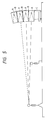
- the focusing directions of the Fresnel lenses provided behind the screens are varied in order to equalize the illuminations from each of the lenses for the center line among them. For example, if the number of the screens is four, the foci of the lenses are placed on the center line among the four screens. For these reasons, it is necessary to take the positions of the lenses into consideration in assembling the multiple projection television receiver. Therefore, it requires some skill to assemble the receiver. Moreover the lenses are not interchangeable, so they cannot be mass-produced and are, therefore, expensive.
- the screens are made flat overall in order to be disposed in the box. For this reason, if the height of the multiple projection television receiver is large, the illumination at the top and bottom of the screen assembly is so low for some eye positions of the viewer of the receiver that he cannot see a sharp picture of uniform luminance.
- the multiple projection television receiver of this invention comprises a plurality of projection television receiver modules, each including a Fresnel lens; a screen located at the front of said receiver modules; three cathode-ray tubes corresponding to the colors red, green and blue, respectively, for projecting a picture from the tubes onto a screen through the Fresnel lens; and means for vertically and horizontally coupling each module to other modules wherein the front surface of said modules adjoining each other are adjacent and located in substantially the same plane.
- projection television receiver modules each of which have the same constitution and include three cathode-ray tubes corresponding to the colors red, green and blue so that a picture is projected from the tubes onto a screen through a Fresnel lens, are vertically and horizontally coupled to each other so that the front surfaces of the modules adjoining each other are coincident with each other or located in the same plane. It is preferable that the modules in upper positions are inclined forward relative to the modules in lower positions.
- the projection television receiver modules can be vertically coupled to each other by a coupling device in which couplers are secured to the tops of the lower modules so that the upper modules are placed on the couplers; and bolts engaged in tapped holes provided at the bottoms of the upper modules are inserted into the couplers so that the bolts can be tightened or loosened to move the upper modules back or forth relative to the lower modules, for adjustment.
- the height of each of the couplers may be greater at the rear end of the coupler than at the front end thereof to incline the upper modules forward relative to the lower modules.
- the preferred embodiment of a multiple projection television receiver comprises a plurality of projection television receiver modules A and a plurality of couplers B for coupling the modules to each other vertically as shown in FIG. 5.
- Each of modules A comprises a casing 1; three cathode-ray tubes (not shown in the drawings) provided in the rear portion of the casing corresponding to the colors red, green and blue, respectively; a screen 2 (generally referred to as a lenticular lens) provided on the front of the casing; and a Fresnel lens 13 shown in Fig. 7 provided behind the screen. All the modules A have the same lenticular lenses 2 and the same Fresnel lenses 13.
- Two handholds 3 for carrying the module A are provided on each of the right and left sides of the casing 1.
- Two hanger rings 4 for suspending the module A while positioning it are provided on casing 1 near each of the right and left side edges of the top thereof.
- Each of fasteners 5 has an engaging bar 5b which is moved back and forth by turning a handle 5a up and down.
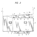
- Two fasteners 5 are attached to the top of the casing 1 at one side edge of the top, as shown in FIG. 3.
- Two stoppers 6 are attached to the top of the casing 1 at the side edge opposite fasteners 5 on the top, as shown in FIG. 3.
- Feet 7′ and 7 are secured to the corresponding front and rear portions, respectively, of the bottom of casing 1 of each module A so that the feet extend from one side to the other of the casing. Hooks 8 for tentative attachment are provided on the bottom of the casing 1 of each module A at both the side edges of the bottom slightly behind the front feet 7′.
- Each of the rear feet 7 has two screw insertion holes 7a at both the sides of the rear foot.
- a nut 7b is secured to one side of each rear foot 7 concentrically to the screw insertion hole 7a.
- couplers B are secured to the tops of the modules A except for the uppermost modules, and each include a pair of slender members 9 secured to the top of casing 1 of the corresponding module near the right and left side edges, respectively, of the top by screws or the like.
- the cross section of each slender member 9 is U-shaped.
- the height of each slender member 9 is gradually decreased from the rear end thereof toward the front end thereof.
- Three reinforcing members 10 are welded to each slender member 9.
- the rear reinforcing member 10 has two screw insertion holes 10a, which coincide with the screw insertion holes 7a of the corresponding rear foot 7.
- a nut 10b is secured to one side of the rear reinforcing member 10 concentrically to the screw insertion hole 10a corresponding to the screw insertion hole 7a at which the nut 7b is not secured.
- the upper portion of each slender member 9 has a notch 9a, in which the corresponding rear foot 7 is fitted.
- the other couplers B are secured to the bottom of the lowermost modules A, as shown in FIG. 2.
- the slender members 9′ of these couplers B are the same as those 9 of the preceding couplers B except that the height of each of the slender members 9′ is uniform from the rear end thereof to the front end thereof.
- the slender members 9′ can be secured not only to the lowermost modules A, but also to the other modules A to couple them to each other in parallel with each other.
- a procedure of coupling all the projection television receiver modules A to each other by the couplers B to assemble the multiple projection television receiver will now be described.
- Slender members 9 of couplers B are secured to the tops of modules A by screws or the like except for the uppermost modules.
- the slender members 9′ of the other couplers B are secured to the bottoms of the lowermost modules A to secure the modules to bases C by the slender members, as shown in FIGS. 5 and 6.
- a television reception means, a control circuit for sending out divided video signals to the cathode-ray tubes, loudspeakers and so forth are housed in the bases C.
- the lowermost modules A juxtaposed together are coupled to each other by the fasteners 5 and the stoppers 6 attached to the tops of the casings 1 of the modules, so that no gap is made between the modules.
- the second lowermost modules A are then placed on the lowermost ones by hanging the second lowermost modules by hanger rings 4 with a hoist or the like.
- the hooks 8 provided on the bottom of the second lowermost modules A are engaged with the slender members 9 provided on the tops of the lowermost modules A, and the feet 7 provided on the second lowermost modules A, and the feet 7 provided on the second lowermost modules are fitted in the notches 9a of the slender members 9 provided on the lowermost modules.
- the module of the multiple projection television receiver provided in accordance with the present invention are vertically coupled to each other by the coupling device having the couplers, the height of each of which is greater at the rear end of the coupler than at the front end thereof, the upper modules A are inclined forward relative to the lower modules A as shown in FIG. 5.
- the resultant assembly is not completely planar but has a forward inclination so that a viewer even at a short distance from the multiple projection television receiver can see the pictures on the upper modules in sharp focus.
- the vertical and horizontal angles of the field of vision of the viewer to each module are normally ⁇ 10° and ⁇ 40°, respectively.
- modules A are coupled to each other as shown in FIG. 6 or the multiple projection television receiver is viewed from a relatively long distance, the upper modules do not need to be inclined forward relative to the lower modules and therefore all of the screens are located in the same plane. In that case, modules A are coupled to each other by the couplers B having slender members 9′, the height of each of which is uniform from the rear end of the member to the front end thereof.
- the thickness of the thin front frame 14 of the casing 1 of each module A which is shown in FIG. 7, is set at 5.5 mm to minimized the width of the portion of the multiple projection television receiver which does not display any picture, shown in FIG. 8.
- an aluminum box 19 and a steel plate 16 of 1.6mm in thickness are secured to each other by countersunk screws 18 to constitute casing 1.
- the screen 2 made of a lenticular sheet 12 and the Fresnel lens 13 are fitted on a rubber pad 15 and secured to the casing by frame 14 and countersunk screws 17, so that the screen can be detached from the front of casing 1, for replacement, when the screen is scratched or damaged.
- projection television receiver modules of the same construction can be easily vertically and horizontally coupled to each other by couplers to assemble a multiple projection television receiver, and can be easily uncoupled from each other to disassemble the receiver for transportation, storage or the like. Since any number of the modules to be coupled to each other can be choosen, the size of the receiver can be easily changed. The cost of the receiver is reduced since the modules are substantially identical.
- Couplers the height of each of which is decreased from the rear end thereof toward the front end thereof can be used to couple the modules to each other to incline the upper modules forward relative to the lower modules to enable a viewer to see a sharp picture on the receiver regardless of the position of the viewer. Desirable effects are thus produced.
Landscapes
- Engineering & Computer Science (AREA)
- Multimedia (AREA)
- Signal Processing (AREA)
- Transforming Electric Information Into Light Information (AREA)
- Video Image Reproduction Devices For Color Tv Systems (AREA)
- Devices For Indicating Variable Information By Combining Individual Elements (AREA)
- Projection Apparatus (AREA)
Applications Claiming Priority (2)
| Application Number | Priority Date | Filing Date | Title |
|---|---|---|---|
| JP63052574A JPH0787561B2 (ja) | 1988-03-08 | 1988-03-08 | プロジェクションテレビユニット及びマルチプロジェクションテレビの連結部材 |
| JP52574/88 | 1988-03-08 |
Publications (3)
| Publication Number | Publication Date |
|---|---|
| EP0331847A2 true EP0331847A2 (de) | 1989-09-13 |
| EP0331847A3 EP0331847A3 (en) | 1990-09-19 |
| EP0331847B1 EP0331847B1 (de) | 1994-05-04 |
Family
ID=12918579
Family Applications (1)
| Application Number | Title | Priority Date | Filing Date |
|---|---|---|---|
| EP88311630A Expired - Lifetime EP0331847B1 (de) | 1988-03-08 | 1988-12-08 | Mehrfachprojektionsfernsehempfänger |
Country Status (4)
| Country | Link |
|---|---|
| US (2) | US4903137A (de) |
| EP (1) | EP0331847B1 (de) |
| JP (1) | JPH0787561B2 (de) |
| DE (1) | DE3889447T2 (de) |
Cited By (12)
| Publication number | Priority date | Publication date | Assignee | Title |
|---|---|---|---|---|
| GB2248005A (en) * | 1990-09-03 | 1992-03-18 | Pioneer Electronic Corp | Multiple screen image projection system |
| EP0464663A3 (en) * | 1990-06-29 | 1992-04-15 | Matsushita Electric Industrial Co., Ltd. | Projection-type television set |
| FR2674090A1 (fr) * | 1991-03-15 | 1992-09-18 | Video Scoper France | Procede pour generer simultanement un ensemble d'images video sur un support de visualisation, et systemes pour sa mise en óoeuvre. |
| EP0471478A3 (en) * | 1990-08-03 | 1993-02-24 | Mitsubishi Denki Kabushiki Kaisha | Large screen display apparatus |
| US5264941A (en) * | 1990-08-03 | 1993-11-23 | Mitsubishi Denki Kabushiki Kaisha | Large screen display apparatus utilizing a transparent plate to display an image over an entire surface of a diffusing surface |
| EP0567330A3 (en) * | 1992-04-23 | 1993-12-22 | Pioneer Electronic Corp | Projection television set |
| WO1994017637A1 (en) * | 1993-01-22 | 1994-08-04 | C.D. Interactive Ltd. | Video display system |
| US5361078A (en) * | 1990-02-16 | 1994-11-01 | Nadimelia Limited | Multiple screen graphics display |
| EP0715458A3 (de) * | 1992-04-23 | 1996-10-16 | Pioneer Electronic Corp | Projektionsfernsehgerät |
| WO1997031478A1 (en) * | 1996-02-22 | 1997-08-28 | Gennady Ivanovich Judenich | Information video system |
| WO1998027726A1 (en) * | 1996-12-17 | 1998-06-25 | Barco N.V. | Light shield for image reproduction devices placed next to and/or above one another |
| ITRM20090164A1 (it) * | 2009-04-10 | 2010-10-11 | Crisotech Italy S R L | Struttura di montaggio per pareti video e simili. |
Families Citing this family (17)
| Publication number | Priority date | Publication date | Assignee | Title |
|---|---|---|---|---|
| JPH0617381Y2 (ja) * | 1990-04-28 | 1994-05-02 | 有限会社エム・アイ・シー工業 | マルチ映像装置 |
| JPH04212580A (ja) * | 1990-11-20 | 1992-08-04 | Pioneer Electron Corp | プロジェクションテレビにおけるスクリーン固定装置 |
| JPH04309084A (ja) * | 1991-04-05 | 1992-10-30 | Sony Corp | 映像表示装置 |
| CN2109032U (zh) * | 1991-10-23 | 1992-07-01 | 何开生 | 电视机立体成像装置 |
| JP2750041B2 (ja) * | 1992-04-23 | 1998-05-13 | パイオニア株式会社 | プロジェクションテレビ |
| US5523790A (en) * | 1994-09-07 | 1996-06-04 | Kalua; Kevin A. | Modular video wall system |
| DE69522285T2 (de) * | 1994-10-14 | 2002-05-16 | Kabushiki Kaisha Toshiba, Kawasaki | Mehrschirmanzeigevorrichtung |
| USD384343S (en) * | 1995-05-23 | 1997-09-30 | Kabushiki Kaisha Toshiba | Projection type monitor TV receiver system |
| EP0911685B1 (de) * | 1997-04-18 | 2006-12-20 | Sony Corporation | Haltevorrichtung für durchsichtprojektionsschirm, verfahren zum halten des schirmes, schirmhaltefilm und verfahren zum halten des filmes |
| US6088140A (en) * | 1998-02-05 | 2000-07-11 | Zebra Imaging, Inc. | Segmented display system for large, continuous autostereoscopic images |
| US6456339B1 (en) | 1998-07-31 | 2002-09-24 | Massachusetts Institute Of Technology | Super-resolution display |
| US6152739A (en) * | 1998-11-20 | 2000-11-28 | Mcdonnell Douglas Corporation | Visual display system for producing a continuous virtual image |
| JP4502339B2 (ja) * | 1999-09-20 | 2010-07-14 | キヤノン株式会社 | 位置決め保持機構を有する画像投影装置 |
| US6921174B1 (en) | 2000-01-27 | 2005-07-26 | Thomson Licensing, S.A. | Projection television cabinet having a one-piece reference structure |
| US20030063227A1 (en) * | 2001-10-03 | 2003-04-03 | Whitelaw Jeffrey G. | Integrated modular projection television system |
| JP5012463B2 (ja) | 2007-12-03 | 2012-08-29 | セイコーエプソン株式会社 | 走査型画像表示システム及び走査型画像表示装置 |
| JP6638417B2 (ja) * | 2016-01-19 | 2020-01-29 | セイコーエプソン株式会社 | プロジェクター及びプロジェクションシステム |
Family Cites Families (12)
| Publication number | Priority date | Publication date | Assignee | Title |
|---|---|---|---|---|
| US3450454A (en) * | 1967-10-27 | 1969-06-17 | Diebold Inc | Modular tv monitor housing and stand |
| US3909525A (en) * | 1973-12-10 | 1975-09-30 | Rockwell International Corp | Display system optics |
| US4274110A (en) * | 1980-01-08 | 1981-06-16 | Zenith Radio Corporation | Projection television system |
| US4368485A (en) * | 1981-04-13 | 1983-01-11 | Zenith Radio Corporation | Billboard large screen TV |
| JPS6016179A (ja) * | 1983-07-07 | 1985-01-26 | Toshiba Corp | パルス巾変調インバ−タの電流制御装置 |
| FR2549671B1 (fr) * | 1983-07-22 | 1987-05-22 | Thomson Csf | Dispositif d'affichage d'une image de television de grandes dimensions et recepteur de television comportant un tel dispositif |
| JPS6074891A (ja) * | 1983-09-30 | 1985-04-27 | Nec Home Electronics Ltd | 6管式マルチプロジエクタ |
| JPS6168292A (ja) * | 1984-09-12 | 1986-04-08 | Hokuetsu Seishi Kk | 感熱記録材料 |
| JPH0143739Y2 (de) * | 1984-10-11 | 1989-12-19 | ||
| JPS62296677A (ja) * | 1986-06-17 | 1987-12-23 | Matsushita Electric Ind Co Ltd | 映像表示装置 |
| US4734779A (en) * | 1986-07-18 | 1988-03-29 | Video Matrix Corporation | Video projection system |
| US4866530A (en) * | 1988-02-22 | 1989-09-12 | Kalua Kevin A | Multiple screen, modular video display projection system |
-
1988
- 1988-03-08 JP JP63052574A patent/JPH0787561B2/ja not_active Expired - Fee Related
- 1988-12-06 US US07/280,919 patent/US4903137A/en not_active Ceased
- 1988-12-08 EP EP88311630A patent/EP0331847B1/de not_active Expired - Lifetime
- 1988-12-08 DE DE3889447T patent/DE3889447T2/de not_active Expired - Fee Related
-
1992
- 1992-02-07 US US07/832,337 patent/USRE34689E/en not_active Expired - Lifetime
Cited By (15)
| Publication number | Priority date | Publication date | Assignee | Title |
|---|---|---|---|---|
| US5361078A (en) * | 1990-02-16 | 1994-11-01 | Nadimelia Limited | Multiple screen graphics display |
| EP0464663A3 (en) * | 1990-06-29 | 1992-04-15 | Matsushita Electric Industrial Co., Ltd. | Projection-type television set |
| EP0471478A3 (en) * | 1990-08-03 | 1993-02-24 | Mitsubishi Denki Kabushiki Kaisha | Large screen display apparatus |
| US5264941A (en) * | 1990-08-03 | 1993-11-23 | Mitsubishi Denki Kabushiki Kaisha | Large screen display apparatus utilizing a transparent plate to display an image over an entire surface of a diffusing surface |
| GB2248005B (en) * | 1990-09-03 | 1994-08-17 | Pioneer Electronic Corp | Projection image system and assembling system therefor |
| GB2248005A (en) * | 1990-09-03 | 1992-03-18 | Pioneer Electronic Corp | Multiple screen image projection system |
| FR2674090A1 (fr) * | 1991-03-15 | 1992-09-18 | Video Scoper France | Procede pour generer simultanement un ensemble d'images video sur un support de visualisation, et systemes pour sa mise en óoeuvre. |
| US5363149A (en) * | 1992-04-23 | 1994-11-08 | Pioneer Electronic Corporation | Projection television set |
| EP0567330A3 (en) * | 1992-04-23 | 1993-12-22 | Pioneer Electronic Corp | Projection television set |
| EP0715458A3 (de) * | 1992-04-23 | 1996-10-16 | Pioneer Electronic Corp | Projektionsfernsehgerät |
| WO1994017637A1 (en) * | 1993-01-22 | 1994-08-04 | C.D. Interactive Ltd. | Video display system |
| WO1997031478A1 (en) * | 1996-02-22 | 1997-08-28 | Gennady Ivanovich Judenich | Information video system |
| WO1998027726A1 (en) * | 1996-12-17 | 1998-06-25 | Barco N.V. | Light shield for image reproduction devices placed next to and/or above one another |
| BE1010811A5 (nl) * | 1996-12-17 | 1999-02-02 | Barco Nv | Lichtafscherming voor naast en/of boven elkaar geplaatste beeldweergave-inrichtingen. |
| ITRM20090164A1 (it) * | 2009-04-10 | 2010-10-11 | Crisotech Italy S R L | Struttura di montaggio per pareti video e simili. |
Also Published As
| Publication number | Publication date |
|---|---|
| JPH0787561B2 (ja) | 1995-09-20 |
| EP0331847A3 (en) | 1990-09-19 |
| DE3889447D1 (de) | 1994-06-09 |
| USRE34689E (en) | 1994-08-09 |
| US4903137A (en) | 1990-02-20 |
| DE3889447T2 (de) | 1994-11-10 |
| JPH01228281A (ja) | 1989-09-12 |
| EP0331847B1 (de) | 1994-05-04 |
Similar Documents
| Publication | Publication Date | Title |
|---|---|---|
| US4903137A (en) | Projection television receiver comprised of modular array of individual RGB projectors | |
| US10012368B2 (en) | Angle and alignment adjusting method for a display | |
| US6677918B2 (en) | Light emitting diode display system | |
| EP1995508B1 (de) | Flachbildschirmgerät | |
| US6056406A (en) | Projection system having multiple screens | |
| US5382990A (en) | Projector of a rear projection type | |
| US5206760A (en) | Multiprojection apparatus | |
| KR100751898B1 (ko) | 엘이디 전광판의 프레임 구조 | |
| US4984871A (en) | Optical rear projection screen hanger assembly | |
| US5631715A (en) | Stackable modular projection television display systems | |
| US6594078B2 (en) | Interlocking mounting package having separatable chassis for use in multiscreen projection displays | |
| US5523790A (en) | Modular video wall system | |
| US4621293A (en) | Integrated lens and CRT mount for projection TV | |
| US5402263A (en) | Rear projector having an angled screen mounting frame | |
| EP0193088A2 (de) | Durchlichtprojektionsschirm | |
| JP2000137288A (ja) | マルチスタッキング投写装置 | |
| US6181490B1 (en) | Optically adjusting device | |
| US6028701A (en) | Stairstep interlock mounting package for multiscreen projection displays | |
| US6574040B1 (en) | Method and apparatus for supporting one or more seamless rear projector screens | |
| JP2637334B2 (ja) | マルチプロジェクションテレビ | |
| JPH06245177A (ja) | マルチビジョン | |
| US20030231409A1 (en) | Multiple lens support | |
| JP3478964B2 (ja) | 円弧形マルチビジョン | |
| JPH07219057A (ja) | 立体表示用スクリーン | |
| JPH06130495A (ja) | 組合せ形投写形表示装置 |
Legal Events
| Date | Code | Title | Description |
|---|---|---|---|
| PUAI | Public reference made under article 153(3) epc to a published international application that has entered the european phase |
Free format text: ORIGINAL CODE: 0009012 |
|
| AK | Designated contracting states |
Kind code of ref document: A2 Designated state(s): BE DE FR GB IT NL |
|
| PUAL | Search report despatched |
Free format text: ORIGINAL CODE: 0009013 |
|
| AK | Designated contracting states |
Kind code of ref document: A3 Designated state(s): BE DE FR GB IT NL |
|
| 17P | Request for examination filed |
Effective date: 19901213 |
|
| 17Q | First examination report despatched |
Effective date: 19921001 |
|
| GRAA | (expected) grant |
Free format text: ORIGINAL CODE: 0009210 |
|
| AK | Designated contracting states |
Kind code of ref document: B1 Designated state(s): BE DE FR GB IT NL |
|
| REF | Corresponds to: |
Ref document number: 3889447 Country of ref document: DE Date of ref document: 19940609 |
|
| ITF | It: translation for a ep patent filed | ||
| ET | Fr: translation filed | ||
| PLBE | No opposition filed within time limit |
Free format text: ORIGINAL CODE: 0009261 |
|
| STAA | Information on the status of an ep patent application or granted ep patent |
Free format text: STATUS: NO OPPOSITION FILED WITHIN TIME LIMIT |
|
| 26N | No opposition filed | ||
| REG | Reference to a national code |
Ref country code: GB Ref legal event code: 746 Effective date: 19951115 |
|
| REG | Reference to a national code |
Ref country code: FR Ref legal event code: D6 |
|
| PGFP | Annual fee paid to national office [announced via postgrant information from national office to epo] |
Ref country code: GB Payment date: 19991208 Year of fee payment: 12 |
|
| PGFP | Annual fee paid to national office [announced via postgrant information from national office to epo] |
Ref country code: DE Payment date: 19991210 Year of fee payment: 12 |
|
| PGFP | Annual fee paid to national office [announced via postgrant information from national office to epo] |
Ref country code: NL Payment date: 19991228 Year of fee payment: 12 |
|
| PGFP | Annual fee paid to national office [announced via postgrant information from national office to epo] |
Ref country code: FR Payment date: 19991229 Year of fee payment: 12 |
|
| PGFP | Annual fee paid to national office [announced via postgrant information from national office to epo] |
Ref country code: BE Payment date: 20000217 Year of fee payment: 12 |
|
| PG25 | Lapsed in a contracting state [announced via postgrant information from national office to epo] |
Ref country code: GB Free format text: LAPSE BECAUSE OF NON-PAYMENT OF DUE FEES Effective date: 20001208 |
|
| PG25 | Lapsed in a contracting state [announced via postgrant information from national office to epo] |
Ref country code: BE Free format text: LAPSE BECAUSE OF NON-PAYMENT OF DUE FEES Effective date: 20001231 |
|
| BERE | Be: lapsed |
Owner name: PIONEER ELECTRONIC CORP. Effective date: 20001231 |
|
| PG25 | Lapsed in a contracting state [announced via postgrant information from national office to epo] |
Ref country code: NL Free format text: LAPSE BECAUSE OF NON-PAYMENT OF DUE FEES Effective date: 20010701 |
|
| GBPC | Gb: european patent ceased through non-payment of renewal fee |
Effective date: 20001208 |
|
| PG25 | Lapsed in a contracting state [announced via postgrant information from national office to epo] |
Ref country code: FR Free format text: LAPSE BECAUSE OF NON-PAYMENT OF DUE FEES Effective date: 20010831 |
|
| NLV4 | Nl: lapsed or anulled due to non-payment of the annual fee |
Effective date: 20010701 |
|
| REG | Reference to a national code |
Ref country code: FR Ref legal event code: ST |
|
| PG25 | Lapsed in a contracting state [announced via postgrant information from national office to epo] |
Ref country code: DE Free format text: LAPSE BECAUSE OF NON-PAYMENT OF DUE FEES Effective date: 20011002 |
|
| PG25 | Lapsed in a contracting state [announced via postgrant information from national office to epo] |
Ref country code: IT Free format text: LAPSE BECAUSE OF NON-PAYMENT OF DUE FEES;WARNING: LAPSES OF ITALIAN PATENTS WITH EFFECTIVE DATE BEFORE 2007 MAY HAVE OCCURRED AT ANY TIME BEFORE 2007. THE CORRECT EFFECTIVE DATE MAY BE DIFFERENT FROM THE ONE RECORDED. Effective date: 20051208 |