EP0330840B1 - Two-function coil-forming assembly - Google Patents
Two-function coil-forming assembly Download PDFInfo
- Publication number
- EP0330840B1 EP0330840B1 EP89101399A EP89101399A EP0330840B1 EP 0330840 B1 EP0330840 B1 EP 0330840B1 EP 89101399 A EP89101399 A EP 89101399A EP 89101399 A EP89101399 A EP 89101399A EP 0330840 B1 EP0330840 B1 EP 0330840B1
- Authority
- EP
- European Patent Office
- Prior art keywords
- assembly
- forming
- drum
- coiled
- feeder
- Prior art date
- Legal status (The legal status is an assumption and is not a legal conclusion. Google has not performed a legal analysis and makes no representation as to the accuracy of the status listed.)
- Expired - Lifetime
Links
Images

Classifications
-
- B—PERFORMING OPERATIONS; TRANSPORTING
- B21—MECHANICAL METAL-WORKING WITHOUT ESSENTIALLY REMOVING MATERIAL; PUNCHING METAL
- B21C—MANUFACTURE OF METAL SHEETS, WIRE, RODS, TUBES, PROFILES OR LIKE SEMI-MANUFACTURED PRODUCTS OTHERWISE THAN BY ROLLING; AUXILIARY OPERATIONS USED IN CONNECTION WITH METAL-WORKING WITHOUT ESSENTIALLY REMOVING MATERIAL
- B21C47/00—Winding-up, coiling or winding-off metal wire, metal band or other flexible metal material characterised by features relevant to metal processing only
- B21C47/02—Winding-up or coiling
- B21C47/04—Winding-up or coiling on or in reels or drums, without using a moving guide
- B21C47/045—Winding-up or coiling on or in reels or drums, without using a moving guide in rotating drums
-
- B—PERFORMING OPERATIONS; TRANSPORTING
- B21—MECHANICAL METAL-WORKING WITHOUT ESSENTIALLY REMOVING MATERIAL; PUNCHING METAL
- B21C—MANUFACTURE OF METAL SHEETS, WIRE, RODS, TUBES, PROFILES OR LIKE SEMI-MANUFACTURED PRODUCTS OTHERWISE THAN BY ROLLING; AUXILIARY OPERATIONS USED IN CONNECTION WITH METAL-WORKING WITHOUT ESSENTIALLY REMOVING MATERIAL
- B21C47/00—Winding-up, coiling or winding-off metal wire, metal band or other flexible metal material characterised by features relevant to metal processing only
- B21C47/02—Winding-up or coiling
- B21C47/10—Winding-up or coiling by means of a moving guide
- B21C47/14—Winding-up or coiling by means of a moving guide by means of a rotating guide, e.g. laying the material around a stationary reel or drum
- B21C47/143—Winding-up or coiling by means of a moving guide by means of a rotating guide, e.g. laying the material around a stationary reel or drum the guide being a tube
Definitions
- This invention concerns a two-function coil-forming assembly according to the preamble of claim 1.
- the invention concerns a coil-forming assembly suitable to cooperate with a drum forming coiled bundles of wire having a diameter ranging from 10 to 20 mm. or greater.
- Such wire is produced by hot-rolling and comes from a rolling line positioned upstream.
- a proposal in the name of the present applicant exists according to which two pairs of headstocks, of which each pair comprises a pre-bending Garrett headstock and an Edenborn headstock, are provided in a cooling line at the sides of a Garrett-type turret forming coiled bundles.
- These units feeding the turret that forms coiled bundles are fed by channels which feed rolled stock and comprise suitable switching means.
- the present applicant has now shown that it is possible to overcome the shortcomings of the above proposal and to arrange for the coil-forming unit to be in direct, immediate cooperation with the turret or drum forming the coiled bundles and at the same time to work with feeder units having different individual functions.
- Such feeder units may consist of an Edenborn-type headstock or a Garrett-type pre-bending assembly.
- a first advantage is the fact that, when the rolled stock feeder units are in their working position, they can cooperate with the Garrett-type drum at a position immediately upstream thereof without any substantial break in continuity, thus enabling the coils to be positioned at once in a required manner.
- the invention enables the coiled bundle to be readily discharged by means of a simple lateral movement of the individual feeder unit working at that moment.
- the invention enables the coiled bundles formed in a substantially known manner to be swiftly and easily handled.
- the rotatable column having a substantially vertical axis and bearing at least two different individual feeder units is included in close cooperation with the Garrett drum, whereby such feeder units can consist of an Edenborn headstock and a pre-bending Garrett assembly.
- the two different individual feeder units are positioned substantially at 180° opposite to each other on the rotatable column.
- these different individual feeder units consist of two Edenborn coil-forming headstocks and two pre-bending Garrett assemblies.
- This embodiment of the variant permits that,while one individual feeder unit is working, its twin individual rolled stock feeder unit can undergo maintenance without any need to halt rolling therefor except possibly for a very short time.
- each different individual feeder unit is secured to the rotatable column in such a way that it can be oriented and can therefore be rotated by a required angle in relation to the working position.
- This variant enables the Garrett drum to be freed momentarily from any encumbrance above it at the end of formation of a coiled bundle, thus allowing a movable plate to rise and lift the coiled bundle so that suitable engagement forks can take the bundle and discharge it onto a removal conveyor.
- two drums forming bundles can cooperate with the position of formation of the coiled bundles so that, when a drum holds a formed bundle, it is displaced for removal thereof while the other drum to form coiled bundles takes the place of the first drum.
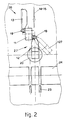
- a feeder assembly or two-function coil-forming assembly 10 comprises a rotatable column 11 having a substantially vertical axis.
- Rotary actuation of the rotatable column 11 and its positioning in a desired specific position are performed with a known system suitable for the purpose.
- the rotatable column 11 cooperates with at least one Garrett drum 20, which in this case comprises a known movable plate 21 able to lift a coiled bundle 22 when formed and bring it up to the level of a removal conveyor 24.
- the rotatable column 11 cooperates with channels 14 and 15 respectively feeding rolled stock belonging to the ranges of rolled rods having sections in the low range and high range of the field of sections envisaged, which covers sections of about 10 mm. in diameter up to 20 mm. or more in diameter.
- Each of the feed channels 14-15 cooperates respectively with a different individual feeder unit 25 when the feeder unit is in its working position.
- the feed channel 15 cooperating with a pre-bending assembly 13 in avoiding any danger of contact when the pre-bending assembly 13 is in its inactive position or when it is moving to that position may comprise a retractable portion or element 16 which frees the zone taken up when functioning is taking place in a known manner.
- the feed channel 15 feeds the rolled stock thereto, and the rolled stock is taken, pre-bent, fed onwards and delivered by rollers 17.
- the different individual feeder units 25 are secured to the rotatable column 11.
- one of the individual different feeder units 25 consists of an Edenborn coil-forming headstock 12, while the other is a pre-bending Garrett assembly 13.
- the different individual feeder units 25, being an Edenborn coil-forming headstock 12 and a pre-bending assembly 13, can be oriented by a jack 18, for instance, on the axis of the inclined arm attachment 19.
- This jack 18 is anchored to the rotatable column 11 and to the feeder unit 25.
- the coil-forming headstock 12 and the pre-bending assembly 13 can take up an inactive position 26 and a coiling and working position 27.
- the feeder units 25 when they are in their working position 27, they can take up a first working or coiling position 27 and a second position 127 for removal of coiled bundles.
- This second position 127 is such that it frees momentarily the upper part of the Garrett drum 20.
- orientation of the feeder units 25 can also be achieved by acting on the rotatable column 11.
Landscapes
- Engineering & Computer Science (AREA)
- Mechanical Engineering (AREA)
- Winding, Rewinding, Material Storage Devices (AREA)
- Unwinding Webs (AREA)
- Specific Conveyance Elements (AREA)
- Replacement Of Web Rolls (AREA)
- Containers And Plastic Fillers For Packaging (AREA)
- Pharmaceuticals Containing Other Organic And Inorganic Compounds (AREA)
Priority Applications (1)
| Application Number | Priority Date | Filing Date | Title |
|---|---|---|---|
| AT89101399T ATE69745T1 (de) | 1988-02-29 | 1989-01-27 | Wickelanlage mit zwei wirkungsweisen. |
Applications Claiming Priority (2)
| Application Number | Priority Date | Filing Date | Title |
|---|---|---|---|
| IT8883330A IT1234883B (it) | 1988-02-29 | 1988-02-29 | Gruppo formaspire a doppia destinazione. |
| IT8333088 | 1988-02-29 |
Publications (2)
| Publication Number | Publication Date |
|---|---|
| EP0330840A1 EP0330840A1 (en) | 1989-09-06 |
| EP0330840B1 true EP0330840B1 (en) | 1991-11-27 |
Family
ID=11320242
Family Applications (1)
| Application Number | Title | Priority Date | Filing Date |
|---|---|---|---|
| EP89101399A Expired - Lifetime EP0330840B1 (en) | 1988-02-29 | 1989-01-27 | Two-function coil-forming assembly |
Country Status (6)
| Country | Link |
|---|---|
| US (1) | US4932231A (it) |
| EP (1) | EP0330840B1 (it) |
| AT (1) | ATE69745T1 (it) |
| DE (1) | DE68900458D1 (it) |
| ES (1) | ES2028378T3 (it) |
| IT (1) | IT1234883B (it) |
Families Citing this family (2)
| Publication number | Priority date | Publication date | Assignee | Title |
|---|---|---|---|---|
| DE4105514A1 (de) * | 1991-02-22 | 1992-08-27 | Buderus Schleiftechnik | Vorrichtung zum biegen von draht in aneinanderhaengenden windungen |
| JP2002542575A (ja) | 1999-04-08 | 2002-12-10 | シュロニガー ホールディング アーゲー | ケーブル加工装置の制御方法、ケーブル加工装置及びケーブル加工装置を備えたシステム |
Family Cites Families (7)
| Publication number | Priority date | Publication date | Assignee | Title |
|---|---|---|---|---|
| US2073928A (en) * | 1934-03-03 | 1937-03-16 | Schloemann Ag | Reel for coiling wire |
| DE1000769B (de) * | 1952-06-18 | 1957-01-17 | Sack Gmbh Maschf | Wahlweise mit oder ohne Drallbildung arbeitender Vertikalhaspel |
| GB712799A (en) * | 1952-07-15 | 1954-07-28 | Herman Bocher | Improvements in and relating to wire winding blocks |
| US3020000A (en) * | 1957-11-27 | 1962-02-06 | Morgan Construction Co | Reeling apparatus |
| DE1237049B (de) * | 1962-04-16 | 1967-03-23 | Siemag Siegener Masch Bau | Wahlweise im Garret- oder im Edenborn-System betreibbarer Vertikal-Warmdrahthaspel |
| FR2533201A1 (fr) * | 1982-09-20 | 1984-03-23 | Cables De Lyon Geoffroy Delore | Machine automatique de lovage d'un cable |
| IT210789Z2 (it) * | 1986-12-02 | 1989-01-11 | Danieli Off Mecc | Linea raffreddamento matasse di filo laminato. |
-
1988
- 1988-02-29 IT IT8883330A patent/IT1234883B/it active
-
1989
- 1989-01-27 DE DE8989101399T patent/DE68900458D1/de not_active Expired - Fee Related
- 1989-01-27 EP EP89101399A patent/EP0330840B1/en not_active Expired - Lifetime
- 1989-01-27 AT AT89101399T patent/ATE69745T1/de not_active IP Right Cessation
- 1989-01-27 ES ES198989101399T patent/ES2028378T3/es not_active Expired - Lifetime
- 1989-02-10 US US07/308,477 patent/US4932231A/en not_active Expired - Lifetime
Also Published As
| Publication number | Publication date |
|---|---|
| IT8883330A0 (it) | 1988-02-29 |
| EP0330840A1 (en) | 1989-09-06 |
| DE68900458D1 (de) | 1992-01-09 |
| IT1234883B (it) | 1992-06-02 |
| ES2028378T3 (es) | 1992-07-01 |
| ATE69745T1 (de) | 1991-12-15 |
| US4932231A (en) | 1990-06-12 |
Similar Documents
| Publication | Publication Date | Title |
|---|---|---|
| US4735040A (en) | Method of and apparatus for the automatic feeding of filled cans and the automatic removal of empty cans from the spinning units of a spinning machine | |
| US4993253A (en) | Drawing unit downstream of a bending assembly and method to bend the trailing end of bars | |
| US6332588B1 (en) | Coiling machine for hot rolled stock such as strip or sheet | |
| EP0330840B1 (en) | Two-function coil-forming assembly | |
| US3645120A (en) | Coiling apparatus | |
| EP0576890B1 (en) | Assembly to wind-unwind thin slabs | |
| JPH0124704B2 (it) | ||
| US5318276A (en) | Apparatus for conveying rolled stock wound into coils in the reeling installation area | |
| EP0497182B1 (en) | Machine to shear the leading end and take samples from coils of strip | |
| US3700157A (en) | Apparatus for feeding strip-like material to a processing apparatus | |
| US6435352B1 (en) | Sorting machine for stacks of sheet metal panels | |
| CA2137617C (en) | Bending assembly of a bending machine | |
| US3837559A (en) | Strip joining apparatus for rolling mills and the like | |
| CA1119675A (en) | Machine for producing reinforcements, in particular for reinforced concrete, and the reinforcements produced thereby | |
| EP0271129B1 (en) | Line to cool wound bundles of rolled wire and rod | |
| JPH08645B2 (ja) | 支持ロール式のロール裁断機に自動的にスリーブを供給する装置 | |
| JPS643575B2 (it) | ||
| CA1217665A (en) | Apparatus for supporting the mandrel back-up bar of an axial piercing machine for hotworking billets, ingots and the like | |
| US3735880A (en) | Transfer apparatus | |
| US3759125A (en) | Apparatus for gathering and cutting rolled-wire coils | |
| US4723721A (en) | Winding machine | |
| US5501314A (en) | Method for the multiple receipt and discharge of rolled sections onto a cooling plate and device performing such method | |
| US4449386A (en) | Steel pipe rolling mill | |
| US3828598A (en) | Wrapping roll adjustment for a strip coiling machine | |
| US4691874A (en) | Method and apparatus for winding wire rod |
Legal Events
| Date | Code | Title | Description |
|---|---|---|---|
| PUAI | Public reference made under article 153(3) epc to a published international application that has entered the european phase |
Free format text: ORIGINAL CODE: 0009012 |
|
| AK | Designated contracting states |
Kind code of ref document: A1 Designated state(s): AT BE CH DE ES FR GB GR LI LU NL SE |
|
| 17P | Request for examination filed |
Effective date: 19900223 |
|
| 17Q | First examination report despatched |
Effective date: 19910404 |
|
| GRAA | (expected) grant |
Free format text: ORIGINAL CODE: 0009210 |
|
| AK | Designated contracting states |
Kind code of ref document: B1 Designated state(s): AT BE CH DE ES FR GB GR LI LU NL SE |
|
| PG25 | Lapsed in a contracting state [announced via postgrant information from national office to epo] |
Ref country code: SE Effective date: 19911127 Ref country code: NL Effective date: 19911127 Ref country code: LI Effective date: 19911127 Ref country code: GR Free format text: LAPSE BECAUSE OF FAILURE TO SUBMIT A TRANSLATION OF THE DESCRIPTION OR TO PAY THE FEE WITHIN THE PRESCRIBED TIME-LIMIT Effective date: 19911127 Ref country code: CH Effective date: 19911127 |
|
| REF | Corresponds to: |
Ref document number: 69745 Country of ref document: AT Date of ref document: 19911215 Kind code of ref document: T |
|
| REF | Corresponds to: |
Ref document number: 68900458 Country of ref document: DE Date of ref document: 19920109 |
|
| ET | Fr: translation filed | ||
| PG25 | Lapsed in a contracting state [announced via postgrant information from national office to epo] |
Ref country code: LU Free format text: LAPSE BECAUSE OF NON-PAYMENT OF DUE FEES Effective date: 19920131 |
|
| REG | Reference to a national code |
Ref country code: CH Ref legal event code: PL |
|
| NLV1 | Nl: lapsed or annulled due to failure to fulfill the requirements of art. 29p and 29m of the patents act | ||
| REG | Reference to a national code |
Ref country code: ES Ref legal event code: FG2A Ref document number: 2028378 Country of ref document: ES Kind code of ref document: T3 |
|
| PLBE | No opposition filed within time limit |
Free format text: ORIGINAL CODE: 0009261 |
|
| STAA | Information on the status of an ep patent application or granted ep patent |
Free format text: STATUS: NO OPPOSITION FILED WITHIN TIME LIMIT |
|
| 26N | No opposition filed | ||
| REG | Reference to a national code |
Ref country code: GB Ref legal event code: IF02 |
|
| PGFP | Annual fee paid to national office [announced via postgrant information from national office to epo] |
Ref country code: FR Payment date: 20020110 Year of fee payment: 14 |
|
| PGFP | Annual fee paid to national office [announced via postgrant information from national office to epo] |
Ref country code: AT Payment date: 20020111 Year of fee payment: 14 |
|
| PGFP | Annual fee paid to national office [announced via postgrant information from national office to epo] |
Ref country code: GB Payment date: 20020130 Year of fee payment: 14 Ref country code: ES Payment date: 20020130 Year of fee payment: 14 |
|
| PGFP | Annual fee paid to national office [announced via postgrant information from national office to epo] |
Ref country code: DE Payment date: 20020227 Year of fee payment: 14 |
|
| PGFP | Annual fee paid to national office [announced via postgrant information from national office to epo] |
Ref country code: BE Payment date: 20020320 Year of fee payment: 14 |
|
| PG25 | Lapsed in a contracting state [announced via postgrant information from national office to epo] |
Ref country code: GB Free format text: LAPSE BECAUSE OF NON-PAYMENT OF DUE FEES Effective date: 20030127 Ref country code: AT Free format text: LAPSE BECAUSE OF NON-PAYMENT OF DUE FEES Effective date: 20030127 |
|
| PG25 | Lapsed in a contracting state [announced via postgrant information from national office to epo] |
Ref country code: ES Free format text: LAPSE BECAUSE OF NON-PAYMENT OF DUE FEES Effective date: 20030128 |
|
| PG25 | Lapsed in a contracting state [announced via postgrant information from national office to epo] |
Ref country code: BE Free format text: LAPSE BECAUSE OF NON-PAYMENT OF DUE FEES Effective date: 20030131 |
|
| PG25 | Lapsed in a contracting state [announced via postgrant information from national office to epo] |
Ref country code: DE Free format text: LAPSE BECAUSE OF NON-PAYMENT OF DUE FEES Effective date: 20030801 |
|
| GBPC | Gb: european patent ceased through non-payment of renewal fee | ||
| PG25 | Lapsed in a contracting state [announced via postgrant information from national office to epo] |
Ref country code: FR Free format text: LAPSE BECAUSE OF NON-PAYMENT OF DUE FEES Effective date: 20030930 |
|
| REG | Reference to a national code |
Ref country code: FR Ref legal event code: ST |
|
| REG | Reference to a national code |
Ref country code: ES Ref legal event code: FD2A Effective date: 20030128 |