EP0329532B1 - Apparatus for distributing a detergent such as soap or the like, in particular liquid soap - Google Patents
Apparatus for distributing a detergent such as soap or the like, in particular liquid soap Download PDFInfo
- Publication number
- EP0329532B1 EP0329532B1 EP89400368A EP89400368A EP0329532B1 EP 0329532 B1 EP0329532 B1 EP 0329532B1 EP 89400368 A EP89400368 A EP 89400368A EP 89400368 A EP89400368 A EP 89400368A EP 0329532 B1 EP0329532 B1 EP 0329532B1
- Authority
- EP
- European Patent Office
- Prior art keywords
- cartridge
- soap
- tongue
- wall
- chamber
- Prior art date
- Legal status (The legal status is an assumption and is not a legal conclusion. Google has not performed a legal analysis and makes no representation as to the accuracy of the status listed.)
- Expired - Lifetime
Links
Images
Classifications
-
- A—HUMAN NECESSITIES
- A47—FURNITURE; DOMESTIC ARTICLES OR APPLIANCES; COFFEE MILLS; SPICE MILLS; SUCTION CLEANERS IN GENERAL
- A47K—SANITARY EQUIPMENT NOT OTHERWISE PROVIDED FOR; TOILET ACCESSORIES
- A47K5/00—Holders or dispensers for soap, toothpaste, or the like
- A47K5/06—Dispensers for soap
- A47K5/12—Dispensers for soap for liquid or pasty soap
- A47K5/1211—Dispensers for soap for liquid or pasty soap using pressure on soap, e.g. with piston
- A47K5/1215—Dispensers for soap for liquid or pasty soap using pressure on soap, e.g. with piston applied by a peristaltic action
Definitions
- the present invention relates to an apparatus for dispensing a detergent preparation such as soap or the like, in particular liquid soap, according to the preamble of claim 1.
- the presently known dispensing devices can be subdivided into two main categories and, in particular, a first type known as a "free-loading" dispenser, and a second type called in the specific technique, a "cartridge" dispenser.
- the dispensing apparatus is capable of eliminating all the drawbacks of the two categories of dispensers but, preferably, those which belong to the category of dispensers of the cartridge version. Although reference is made to these latter in the present description, the invention can be applied, without particular measures which are not within the reach of those skilled in the art, also to dispensers with a loading tank by the top, closed or not by a cap.
- the dispensing devices include, integral with each other, the cartridge or container of liquid soap, the soap dispensing pump which aims to control the discharge of the latter from the container, and a dispensing valve thanks to which it is possible to adjust and scale the individual doses of soap dispensed.
- a “cartridge” dispenser the whole is arranged inside a container-shaped body of rigid material, generally plastic, which is suitably suspended and fixed to the wall by a any conventional means.
- the container-shaped body is opened and everything inside the container is eliminated, that is to say, the cartridge, the distribution pump and control valve. These components are replaced by an identical set, in which the cartridge is filled with soap.
- a final aspect which positively influences the overall cost of the dispensing device is due to the fact that the refilling of said device is facilitated, since it suffices to remove the cartridge, with the pump and the valve which are integral with it, and to quickly mount a new set.
- the high cost of the cartridge-dispensing pump-regulating valve assembly constitutes a notable drawback.
- the cost of these last two components in addition to that of the cartridge, of course, as an essential element of the dispenser, has an impact on the cost of the individual dose of soap dispensed.
- This device is therefore still relatively expensive compared to a device where only the soap cartridge would have to be changed when it is empty.
- the quality of the tight closure of the appendix 30 of the cartridge 4, therefore the absence of leakage when the device in service is at rest depends largely on the precision with which the cover 2 and the plate 3 are manufactured. It is indeed on this precision that will depend the force with which the boss 27 of the plate 3 is pressed elastically against the inner edge of the opening 19 in order to pinch the appendage 30 of the cartridge 4. From a manufacturing cost point of view, such precision is contradictory with the disposable nature of the elements in question.
- the insertion of the appendix 30 of the cartridge 4 into the opening 19 is inconvenient, because it is first necessary to move the boss 27 away from the inner edge of the opening 19, by deforming the elastic lower part. 21 of the plate 3, and it is then necessary to pass the appendix 30, which is "swollen" by the soap, through the relatively narrow slot thus obtained.
- this known device also comprises, in addition to the base 41 and the cover 42, several molded or shaped parts (rubber band 60, clamping element 61, press 65 and spring 73) which must be assembled or fixed to the cover. 42 or to the base 41.
- the positioning of the soap cartridge 44 in the apparatus is awkward because, after having hung the cartridge on the pins 48 of the base 41, it is then necessary to pass the appendix 58 of the cartridge between the rubber band 60 and the clamping element 61, separating them from one another against the return force of the spring 73.
- one of the main objects of the present invention is to provide a device for dispensing soap, in particular liquid soap which, thanks to its original conformation, allows the elimination of both the dispensing pump and the valve which is associated with it.
- the device while being more economical compared to conventional devices, is extremely simplified, so that any maintenance that it could require is reduced, if not directly eliminated.
- the dispensing device of the invention is produced according to what is indicated in the characterizing part of claim 1.
- Another characteristic of the device according to the invention lies in the fact that it distributes predetermined doses of liquid soap by means of suitable members associated or forming an integral part of the structure of the dispenser and which, acting mutually with each other and with the cartridge or the soap container, cause said predetermined soap doses to exit from the latter.
- the whole is controlled by an operating lever projecting from the container of the device, the operation of which comprises that of the above-mentioned members and, consequently, the discharge of one dose at a time from the cartridge.
- the different doses of liquid to be dispensed accumulate by gravity at the start, opposite the outlet end of the soap container and then, once each dose has been thus formed in this zone, after an operation of the control lever, said dose is ejected from the container of liquid soap. The cycle then repeats for each dose.
- Another advantage derives from the fact that the assembly of the entire device does not require locking elements such as screws or the like or, in general, metallic connection elements. Corrosion phenomena, present in conventional dispensing devices, and extremely damaging, are therefore completely eliminated.
- FIGS. 2, 3 and 4 For a global understanding of the dispensing device according to the invention, reference will first be made to FIGS. 2, 3 and 4, so as to be able to describe briefly and, more particularly, what relates to the invention, in particular the conformation of 1a structure of the device in question.
- Said device comprises a bottom wall 1, having a flat part 1a which will allow the device to be hooked and blocked on a wall.
- This hanging of the wall 1 can be done in any known manner, for example by support hooks able to penetrate into suitable holes provided (and not shown) in part 1a or by means of conventional, essentially planar, adhesive fasteners on the two opposite faces, one of them coming to adhere and to be fixed on a wall while the other will come to adhere and to be fixed on the part 1a of the wall 1.
- Said wall 1 has at the upper part a part inclined towards the front part of the device, designated by 1b, which is provided with support and articulation means of a closing cover 2 of the dispensing device according to the invention which is shown in Figure 2 with the cover 2 in the closed position, while it is partially represented in the open position, by the dashed line of the same figure.
- the rear wall 1a of the dispensing device according to the invention is extended at the lower part by a second part 1c, also inclined towards the front part of the device, so that ultimately, the assembly formed by the rear wall 1a and by parts 1b and 1c, constitutes a body substantially C-shaped, the arms of which deviate from the wall 1a are slightly divergent from one another. More particularly, the length of the part 1c of the rear wall 1a is of a length greater than that of the part 1.
- the part 1c is provided, in its median zone, with an opening 3 which allows the exit towards the outside of a part of a control lever 4, which is articulated inside the dispensing device.
- part 1c of the device comprises, at the upper end of said part 1c, a fixed wall 5, perpendicular to the upper end of part 1c, at the end of which is articulated in a manner any known, the end 4b of the control lever 4.
- Said control lever 4 comprises an arm 4c which will constitute the active arm of the control lever 4, which is arranged in such a way that, overall, the control lever 4 has a substantially Y-shaped conformation, the divergent arms 4a and 4c of which are of different length.
- the arm 4a the length of which is greatest, protrudes outside the dispensing device according to the invention and will be actuated by the user.
- the device according to the invention comprises, associated with the control lever 4, an intermediate wall 6 which, as will be explained more clearly below, is deformable in a limited way to allow the idea to be put into practice solution according to the invention and, ultimately, the operation of the device which is the subject.
- the intermediate wall 6 is attached along one of its edges, in particular the rear edge 6a, to the rear wall 1a of the device according to the invention and this attachment is produced in known manner, by a fixing essentially by engagement, also provided with known elastic means such as for example an elastic blade (not shown) which retains the intermediate wall 6 in the desired position to allow the zones 8 and 9 thereof to be deformed during the operation of the device.
- known elastic means such as for example an elastic blade (not shown) which retains the intermediate wall 6 in the desired position to allow the zones 8 and 9 thereof to be deformed during the operation of the device.
- a substantially rectangular part or tongue 8 is formed, which has a high degree of elastic deformability enabling it to be brought from the initial rest position represented by the solid line in FIG. 2, in two working positions, also represented by solid lines in FIGS. 3 and 4.
- This deformation of the part or tongue 8 of the intermediate wall 6 is achieved by the operation of the control lever 4, in particular by engagement of the end of the branch 4c of the control lever 4 on said tongue 8.
- the control lever 4 has three active positions, the first of which, which is the rest position, being represented by the continuous line in FIG. 2, while the second position for closing the entry end of the terminal appendage of the cartridge or of the bag, is always represented by a continuous line in FIG. 3 and the third, compression of the appendix area of the cartridge containing the dose of soap, is shown in Figure 4.
- the control lever 4 rotates clockwise to bring the part or tab 8 of the intermediate wall 6 into contact with the inner surface of the cover 2, in the zone 2a, after rotation always in the clockwise, to compress the appendix of the cartridge against the inside of the cover 2, in zone 2a.
- the other means mentioned above are constituted, in the illustrated embodiment, by the end portion 9 of the intermediate wall 6 which is located opposite the top of the end edge of the wall 1c of the container 1 of the dispenser.
- the liquid soap container is essentially a bag 10 of flexible plastic material, completely filled with liquid soap 11, visible in the areas of the container 10 where the material has been removed.
- the container 10 has, at the upper end, outside the weld zone 12 which closes the container, a pair of holes 13 by means of which said container is fixed to two projecting parts 14 of the part 1b of the wall 1 of the dispenser container.
- the container 10 is disposed essentially in a vertical position and, near its lower end, it rests on the intermediate wall 6, as shown in more detail in Figures 2, 3 and 4.
- the wall of the cover 2 near its lower end 2a folds back towards the front part of the distributor, so that it is thus substantially parallel to the plane of the intermediate wall 6, to which it faces.
- the container 10 takes, in its zone 10a, of width significantly less than that of the remaining part of the container 10, a substantially flattened shape which will essentially constitute a chamber in which will be formed and from which the different doses of soap will be ejected. liquid.
- the liquid soap 11 flows inside the delimited chamber, in the part 10a of the container 10, by the sole action of gravity.
- the part or tab 8 is in the position shown in Figure 2, in which it exerts no action on the wall bottom of the container 10, in particular at its bottom end 10a, which means that this wall simply presses on the intermediate wall 6 of the container of the device according to the invention.
- the first working position of the control lever 4 is shown in FIG. 3, where it can be seen that said lever has made, under the effect of a manual action on the part of the user, a rotation in the clockwise in the direction of arrow F, by a predetermined angle and by a value such that the end of the branch 4c of the control lever 4 has come into contact with the tongue 8 and the has brought into the position shown on the said figure, in which it causes the closure of the zone 10a of the container 10 upwards, that is to say towards the upper part of the container 10 which is "separated" from the chamber 10a, as explained below.
- the tongue or part 8 of the intermediate wall 6 of the device then performs an additional rotation in the clockwise direction, corresponding to an additional rotation of the control lever 4.
- This action determines a pushing of the soap contained in the terminal part 10a of the container 10, with a tendency of the latter, consequently, to come out of the end container terminal, indicated by 20.
- the terminal end 20 which is essentially a channel-shaped portion of the container 10, is initially closed by a part removable by fracture or cutting 21 when the container 10 is placed in the device as shown in FIG. 2, said removable part 21 being fractured or cut so as to thus release the distribution end 20.
- the cartridge Opposite the channel-shaped part 20, the cartridge has a second pair of holes 13a having a function similar to that of the holes 13, for blocking the cartridge 10 on the container.
- the intermediate wall 6, provided with two parts 8 and 9 which collaborate in the formation of a chamber intended to receive a dose and in the ejection of this- ci, is provided, facing part 8, with a folded part 22, convex in the direction of the internal wall of the cover 2.
- the folded part 22 substantially forms a rib, so that, as shown in FIG. 3, when the control lever 4 causes the rotation of the part 8, the rib 22 comes to close the passage of the soap, from the container 10 to the chamber 10a. It may in fact be noted in FIG.
- part 8 actuated directly by the control lever 4, and of part 9, allows the formation of a dose of liquid soap in the chamber 10a when the control lever 4 is in the position shown in FIG. 2.
- the dose is dispensed when the control lever 4 is brought in, by an additional rotation in the clockwise direction (always in the direction of the arrow F) in the second position of work shown in figure 4.
- Part 8 continues to flex under the thrust of arm 4c of lever 4, until it comes to fully support against the inner face of the cover 2, in zone 2a.
- the soap contained in the zone 10a leaves the channel 20, which opens under the pressure of the soap, which causes the part 9 to bend away from the end part of the cover 2 (enlarged detail of FIG. 4).
- liquid soap container 10 has already been positioned in the position shown in FIG. 1, that is to say with the upper part (hole 13) attached to the rear wall 1 of the container and the terminal part 10a of the latter supported on the intermediate wall 6 and hooked to its lower part via the holes 13a, on lugs, not shown, provided on the intermediate wall 6, more precisely next to its part 9, because this latter part must be able to be move relative to the plane of the intermediate wall 6.
- the area 10a of the cartridge 10 is filled by gravity. Closing the cover 2 of the dispenser closes the channel 20 of the cartridge 10 between said cover and the part 9 of the part 6.
- the dispenser is ready for use.
- the control lever 4 is in the rest position ( Figure 2) and the chamber 10a is filled with soap.
- the soap cannot leave the container 10 since the part 9 of the intermediate wall 6 presses on the end part of the cover 2, which closes the channel 20.
- control lever 4 is released and returns to the starting position by the action of the part 8 which tends, elastically, to return to the starting position shown in FIG. 2.
- the part 9 closes the terminal end 20 of the container 10, so that one can therefore again have the formation of a next dose of soap in the chamber 10a since the two opposite walls of the container 10 which had been put in contact by the rib 22 against the cover 2 in the zone 2a are now separated from each other.
- a small block of elastic material such as for example rubber or the like, designated by 40, is inserted on the terminal part of the tongue 9, which has the function of contributing to the perfect closing of the channel-shaped conduit 20, to avoid loss of soap, such as for example the dropwise flow of said soap when there is no distribution thereof.
- the device according to the invention is finally provided with means for adjusting the stroke and, more precisely, the angle of rotation of the control lever 4, in order to be able to modify the quantity of soap of the individual doses.
- Said means consist of a small block of rigid material 41, fixed in a removable and adjustable manner on the internal part of the branch 1c of the wall 1 of the distribution device, part of which projects through the opening 3 in which the control arm 4a of the control lever 4.
- the length of the block 41 which projects inside said opening due to the fact that it can be modified, will ensure the modification accordingly the angle of rotation of the control lever 4, which can be increased or decreased.
- a box-shaped element 42 essentially parallelepiped, which has at the front part a removable area 43, the whole constituting a covering for the soap cartridge.
- the latter can be sold by providing the box-shaped element 42 with possible ornamental representations, capable of communicating a pleasing aesthetic appearance to said covering.
- the dispensing device will be provided for this purpose, inside, of supports or the like, on which the covering 42 will bear, which now will no longer require the need to provide the holes! 3 since it will be said covering which will support cartridge 10.
- the best known variant is that produced by a loading soap dispenser device using the same inventive concept of the cartridge loader described above.
- a loading soap dispenser device using the same inventive concept of the cartridge loader described above.
- Another remarkable variant concerns means for varying the quantity of the individual doses of soap which, in the embodiment described above, consist of small removable blocks 41.
- Another variant concerns the small elastic sealing block 40 which could on the other hand be disposed on a suitable re-entrant part of the end part of the cover 2, from which it would protrude, coming into contact with the conduit 20.
- Another possible variant or modification of the device according to the invention relates, in general, to the type of liquid which it is able to distribute and which could be not liquid soap, but any other liquid essentially having the same characteristics.
Abstract
Description
La présente invention concerne un appareillaqe pour la distribution d'une préparation détergente telle que savon ou analogue, en particulier de savon liquide, selon le préambule de la revendication 1.The present invention relates to an apparatus for dispensing a detergent preparation such as soap or the like, in particular liquid soap, according to the preamble of claim 1.
Les appareils de distribution actuellement connus peuvent être subdivisés en deux grandes catégories et, en particulier, un premier type connu en tant que distributeur "à chargement libre", et un second type dénommé dans la technique spécifique, distributeur "à cartouche".The presently known dispensing devices can be subdivided into two main categories and, in particular, a first type known as a "free-loading" dispenser, and a second type called in the specific technique, a "cartridge" dispenser.
L'appareil de distribution selon la présente invention est apte à éliminer tous les inconvénients des deux catégories de distributeurs mais, de préférence, ceux qui appartiennent à la catégorie des distributeurs de la version à cartouche. Bien qu'il soit fait référence à ces derniers dans la présente description, l'invention peut être appliquée, sans mesures particulières qui ne soient pas à la portée de l'homme de l'art, aussi à des distributeurs à réservoir à chargement par le haut, fermé ou non par un bouchon.The dispensing apparatus according to the present invention is capable of eliminating all the drawbacks of the two categories of dispensers but, preferably, those which belong to the category of dispensers of the cartridge version. Although reference is made to these latter in the present description, the invention can be applied, without particular measures which are not within the reach of those skilled in the art, also to dispensers with a loading tank by the top, closed or not by a cap.
Comme indiqué plus haut, les appareils de distribution comprennent, solidaires entre eux, la cartouche ou le conteneur de savon liquide, la pompe de distribution de savon qui a pour but de commander la décharge de celui-ci du conteneur, et une soupape de distribution grâce à quoi il est possible de régler et de graduer les doses individuelles de savon distribué.As indicated above, the dispensing devices include, integral with each other, the cartridge or container of liquid soap, the soap dispensing pump which aims to control the discharge of the latter from the container, and a dispensing valve thanks to which it is possible to adjust and scale the individual doses of soap dispensed.
Si l'on se réfère donc à un distributeur "à cartouche", le tout est disposé à l'intérieur d'un corps en forme de conteneur en matériau rigide, généralement en matière plastique, lequel est convenablement suspendu et fixé au mur par un moyen classique quelconque.If we therefore refer to a "cartridge" dispenser, the whole is arranged inside a container-shaped body of rigid material, generally plastic, which is suitably suspended and fixed to the wall by a any conventional means.
Une fois que la quantité de savon contenue dans la cartouche est terminée, on procède à l'ouverture du corps en forme de conteneur et on élimine tout ce qui se trouve à l'intérieur du conteneur, c'est-à-dire, la cartouche, la pompe de distribution et la soupape de régulation. Ces composants sont remplacés par un ensemble identique, dans lequel la cartouche est remplie de savon.Once the quantity of soap contained in the cartridge is finished, the container-shaped body is opened and everything inside the container is eliminated, that is to say, the cartridge, the distribution pump and control valve. These components are replaced by an identical set, in which the cartridge is filled with soap.
Une solution de ce type a été adoptée dans le but évident de réduire, tout au moins sous certains aspects, le coût du distributeur alors que, comme on le verra plus clairement par la suite, d'autres aspects continuent à rendre le coût du distributeur élevé.A solution of this type has been adopted with the obvious aim of reducing, at least in certain aspects, the cost of the distributor whereas, as will be seen more clearly below, other aspects continue to make the cost of the distributor Student.
Parmi les aspects qui contribuent à rendre plus économique le distributeur, on citera sa simplicité de construction qui, en particulier, le rend moins sujet à détérioration. Ce dernier avantage rend par conséquent l'entretien demandé par le dispositif quasiment nul.Among the aspects which contribute to making the distributor more economical, mention may be made of its simplicity of construction which, in particular, makes it less subject to deterioration. This latter advantage consequently makes the maintenance required by the device almost zero.
Le fait donc que la pompe soit éliminée à la fin de la quantité de savon contenue dans la cartouche fait en soi que la durée d'utilisation de la pompe est assez limitée et donc que son usure éventuelle, même limitée, n'influe pas sur son fonctionnement.The fact therefore that the pump is eliminated at the end of the quantity of soap contained in the cartridge means that the duration of use of the pump is quite limited and therefore that its possible wear, even limited, does not affect its operation.
Un dernier aspect qui influe positivement sur le coût global du dispositif distributeur est dû au fait que la recharge dudit dispositif est facilitée, car il suffit d'enlever la cartouche, avec la pompe et la soupape qui en sont solidaires, et de monter rapidement un nouvel ensemble.A final aspect which positively influences the overall cost of the dispensing device is due to the fact that the refilling of said device is facilitated, since it suffices to remove the cartridge, with the pump and the valve which are integral with it, and to quickly mount a new set.
Il reste toutefois des inconvénients qui influent négativement sur le coût et la fiabilité de l'appareil de distribution d'une manière non-négligeable.However, there are drawbacks which negatively influence the cost and reliability of the dispensing device in a non-negligible manner.
Sous un premier aspect, le coût élevé de l'ensemble cartouche-pompe de distribution-soupape de régulation constitue un inconvénient notable. En particulier, le coût de ces deux derniers composants, en plus naturellement de celui de la cartouche, en tant qu'élément essentiel du distributeur, vient se répercuter sur le coût de la dose individuelle de savon distribué.In a first aspect, the high cost of the cartridge-dispensing pump-regulating valve assembly constitutes a notable drawback. In particular, the cost of these last two components, in addition to that of the cartridge, of course, as an essential element of the dispenser, has an impact on the cost of the individual dose of soap dispensed.
Un autre inconvénient dérive du fait que, en particulier la pompe de distribution, mais aussi la soupape de distribution, constituent aussi un organe mécanique à pièces mobiles coopérant mutuellement, ce qui fait qu'en définitive on peut avoir de toute façon des grippages ou dommages qui interrompent la distribution de savon contenu dans la cartouche et qui demandent donc, dans tous les cas, un entretien de l'appareil de distribution.Another drawback derives from the fact that, in particular the distribution pump, but also the distribution valve, also constitute a mechanical member with moving parts cooperating with each other, which means that in the end there may be any seizures or damage which interrupt the distribution of soap contained in the cartridge and which therefore require, in all cases, maintenance of the dispensing device.
Il faut noter aussi que la réalisation de la pompe de distribution et celle de la soupape exigent de toute façon que l'on prenne dans les chaînes de fabrication des dispositions qui, même si elles ne sont pas particulièrement complexes, s'avèrent cependant toujours essentielles et coûteuses.It should also be noted that the production of the distribution pump and that of the valve in any case require that arrangements be made in the production lines which, even if they are not particularly complex, are nevertheless always essential. and expensive.
Un autre inconvénient des dispositifs distributeurs conventionnels réside dans le fait que leur simplicité de construction est un fait objectivement relatif étant donné que le nombre d'éléments constituants desdits distributeurs est, de toute façon, élevé.Another drawback of conventional dispensing devices lies in the fact that their simplicity of construction is an objectively relative fact since the number of constituent elements of said dispensers is, in any case, high.
Les inconvénients mentionnés ci-dessus sont en partie éliminés avec les appareils distributeurs décrits dans la demande internationale de brevet WO 81/02094. Toutefois, dans l'appareil représenté sur les figures 1 et 2 de ce document antérieur, seul le socle 1 constitue un élément permanent;The drawbacks mentioned above are partly eliminated with the dispensing devices described in the international patent application WO 81/02094. However, in the device shown in Figures 1 and 2 of this prior document, only the base 1 constitutes a permanent element;
le capot 2, la plaque flexible 3 et la cartouche 4, qui est soudée en 36 au capot 2, forment un ensemble jetable. Cet appareil est donc encore relativement coûteux par rapport à un appareil où seule la cartouche de savon serait à changer lorsqu'elle est vide. En outre, la qualité de la fermeture étanche de l'appendice 30 de la cartouche 4, donc l'absence de fuite lorsque l'appareil en service est au repos, dépend en grande partie de la précision avec laquelle le capot 2 et la plaque 3 sont fabriquées. C'est en effet de cette précision que va dépendre la force avec laquelle le bossage 27 de la plaque 3 est pressé élastiquement contre le bord intérieur de l'ouverture 19 afin de pincer l'appendice 30 de la cartouche 4. D'un point de vue du coût de fabrication, une telle précision est contradictoire avec le caractère jetable des éléments en question. De plus, l'insertion de l'appendice 30 de la cartouche 4 dans l'ouverture 19 est mal commode, car il faut tout d'abord écarter le bossage 27 du bord intérieur de l'ouverture 19, en déformant la partie inférieure élastique 21 de la plaque 3, et il faut ensuite faire passer l'appendice 30, qui est "gonflé" par le savon, à travers la fente relativement étroite ainsi obtenue.the
Dans l'appareil représenté sur les figures 5 et 6 du document WO 81/02094, seule la cartouche 44 a besoin d'être remplacée quand elle est vide. Toutefois, cet appareil connu comporte encore, en plus du socle 41 et du capot 42, plusieurs pièces moulées ou mises en forme (bande de caoutchouc 60, élément de serrage 61, pressoir 65 et ressort 73) qui doivent être assemblées ou fixées au capot 42 ou au socle 41. En outre, ici encore, la mise en place de la cartouche de savon 44, dans l'appareil est mal commode car, après avoir accroché la cartouche sur les ergots 48 du socle 41, il faut ensuite faire passer l'appendice 58 de la cartouche entre la bande de caoutchouc 60 et l'élément de serrage 61 en les écartant l'un de l'autre contre la force de rappel du ressort 73.In the apparatus shown in FIGS. 5 and 6 of document WO 81/02094, only the cartridge 44 needs to be replaced when it is empty. However, this known device also comprises, in addition to the
Il a été maintenant conçu, ce qui constitue l'objet de la présente invention, un appareil distributeur d'une préparation détergente, telle que savon ou analogue, en particulier savon liquide, lequel permet d'éliminer tous les inconvénients qui précèdent.It has now been designed, which constitutes the object of the present invention, a device for dispensing a detergent preparation, such as soap or the like, in particular liquid soap, which makes it possible to eliminate all of the above drawbacks.
Par suite, l'un des objets principaux de la présente invention est de réaliser un dispositif distributeur de savon, en particulier de savon liquide lequel, grâce à sa conformation originale, permet l'élimination tant de la pompe de distribution que de la soupape qui y est associée. Ainsi, le dispositif, tout en étant plus économique par rapport aux dispositifs classiques, est extrêmement simplifié, de sorte que les entretiens éventuels qu'il pourrait demander, se trouvent réduits, si ce n'est directement éliminés.Consequently, one of the main objects of the present invention is to provide a device for dispensing soap, in particular liquid soap which, thanks to its original conformation, allows the elimination of both the dispensing pump and the valve which is associated with it. Thus, the device, while being more economical compared to conventional devices, is extremely simplified, so that any maintenance that it could require is reduced, if not directly eliminated.
A cet effet, l'appareil distributeur de l'invention est réalisé selon ce qui est indiqué dans la partie caractérisante de la revendication 1.To this end, the dispensing device of the invention is produced according to what is indicated in the characterizing part of claim 1.
Une autre caractéristique du dispositif conforme à l'invention réside dans le fait que celui-ci distribue des doses prédéterminées de savon liquide grâce à des organes adéquats associés ou faisant partie intégrante de la structure du distributeur et qui, agissant mutuellement entre eux et avec la cartouche ou le conteneur de savon, provoquent la sortie hors de ce dernier desdites doses de savon prédéterminées. Le tout est commandé par un levier de manoeuvre faisant saillie du conteneur du dispositif, dont la manoeuvre comprend celle des susdits organes et, par conséquent, la décharge d'une dose à la fois de la cartouche.Another characteristic of the device according to the invention lies in the fact that it distributes predetermined doses of liquid soap by means of suitable members associated or forming an integral part of the structure of the dispenser and which, acting mutually with each other and with the cartridge or the soap container, cause said predetermined soap doses to exit from the latter. The whole is controlled by an operating lever projecting from the container of the device, the operation of which comprises that of the above-mentioned members and, consequently, the discharge of one dose at a time from the cartridge.
Selon une autre caractéristique fondamentale du distributeur conforme à l'invention, les différentes doses de liquide à distribuer s'accumulent par gravité au départ, en regard de l'extrémité sortie du conteneur de savon et ensuite, une fois que chaque dose a été ainsi formée dans cette zone, après une manoeuvre du levier de commande, ladite dose est éjectée du conteneur de savon liquide. Le cycle se répète ensuite pour chaque dose.According to another fundamental characteristic of the dispenser according to the invention, the different doses of liquid to be dispensed accumulate by gravity at the start, opposite the outlet end of the soap container and then, once each dose has been thus formed in this zone, after an operation of the control lever, said dose is ejected from the container of liquid soap. The cycle then repeats for each dose.
D'autres caractéristiques et avantages du dispositif distributeur de savon liquide conforme à l'invention ressortiront facilement de la structure décrite ci-dessous d'une forme de réalisation préférée, donnée à titre d'exemple. Ceux-ci peuvent être résumés par le nombre extrêmement réduit de pièces composant le dispositif qui s'avère donc d'un poids extrêmement limité, ce qui constitue des avantages, tant pour le transport que pour l'emballage dudit dispositif.Other characteristics and advantages of the liquid soap dispenser device according to the invention will easily emerge from the structure described below of a preferred embodiment, given by way of example. These can be summarized by the extremely small number of parts making up the device, which therefore proves to be of an extremely limited weight, which constitutes advantages, both for the transport and for the packaging of said device.
Un autre avantage dérive du fait que l'assemblage de l'ensemble du dispositif ne demande pas d'éléments de blocage tels que vis ou analogue ou, en général, d'éléments métalliques de raccordement. On élimine par conséquent totalement les phénomènes de corrosion, présents dans les dispositifs distributeurs classiques, et extrêmement dommageables.Another advantage derives from the fact that the assembly of the entire device does not require locking elements such as screws or the like or, in general, metallic connection elements. Corrosion phenomena, present in conventional dispensing devices, and extremely damaging, are therefore completely eliminated.
On élimine aussi les chaînes de fabrication de la pompe de distribution et de la soupape associée, avec des réductions supplémentaires évidentes de temps et de coûts de construction du dispositif.The production lines of the distribution pump and the associated valve are also eliminated, with Obvious additional reductions in device construction time and costs.
Les caractéristiques et les avantages du dispositif distributeur d'une substance détergente, telle que du savon, généralement du savon liquide, selon l'invention, apparaîtront de façon évidente de la description détaillée suivante d'une forme de réalisation non limitative, faite en se référant aux figures annexées, dans lesquelles:
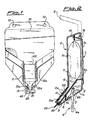
- la figure 1 est une vue de face, partiellement écorchée, de la "cartouche" ou du conteneur de savon liquide dans la position dans laquelle celui-ci est disposé dans le dispositif distributeur conforme à l'invention, ledit dispositif étant représenté, sur cette figure, uniquement pour la partie intéressante aux fins de la compréhension de l'invention,
- la figure 2 est une vue de côté en coupe longitudinale du dispositif distributeur selon l'invention, au repos, c'est-à-dire avant distribution de la dose de savon,
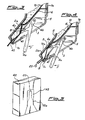
- la figure 3 est une vue latérale à échelle agrandie de la partie du dispositif distributeur selon l'invention, dans laquelle est formée la dose de savon en vue de son éjection ultérieure,
- la figure 4 est une vue latérale analogue aux figures 2 et 3, représentant la phase de distribution de la dose de savon, et
- la figure 5 est une vue schématique en perspective représentant un conteneur de la "cartouche" qui constitue également une réalisation de celle-ci.
- FIG. 1 is a front view, partially cut away, of the "cartridge" or of the liquid soap container in the position in which it is placed in the dispensing device according to the invention, said device being shown, on this figure, only for the part of interest for the understanding of the invention,
- FIG. 2 is a side view in longitudinal section of the dispensing device according to the invention, at rest, that is to say before dispensing the dose of soap,
- FIG. 3 is a side view on an enlarged scale of the part of the dispensing device according to the invention, in which the dose of soap is formed with a view to its subsequent ejection,
- FIG. 4 is a side view similar to FIGS. 2 and 3, showing the phase of dispensing the dose of soap, and
- Figure 5 is a schematic perspective view showing a container of the "cartridge" which also constitutes an embodiment thereof.
Pour une compréhension globale du dispositif distributeur selon l'invention, on se réfèrera tout d'abord aux figures 2, 3 et 4, de manière à pouvoir décrire sommairement et, plus particulièrement, ce qui concerne l'invention, en particulier la conformation de 1a structure du dispositif en question.For a global understanding of the dispensing device according to the invention, reference will first be made to FIGS. 2, 3 and 4, so as to be able to describe briefly and, more particularly, what relates to the invention, in particular the conformation of 1a structure of the device in question.
Ledit dispositif comprend une paroi de fond 1, présentant une partie plane 1a qui permettra l'accrochage et le blocage du dispositif à une paroi. Cet accrochage de la paroi 1 pourra se faire d'une manière quelconque, connue, par exemple par des crochets de support aptes à pénétrer dans des trous appropriés prévus (et non représentés) de la partie 1a ou au moyen d'organes de fixation classiques, essentiellement plans, adhésifs sur les deux faces opposées, l'une d'elles venant adhérer et se fixer sur un mur tandis que l'autre viendra adhérer et se fixer sur la partie 1a de la paroi 1.Said device comprises a bottom wall 1, having a
Ladite paroi 1 présente à la partie supérieure une partie inclinée vers la partie antérieure du dispositif, désignée par 1b, laquelle est pourvue de moyens de support et d'articulation d'un couvercle de fermeture 2 du dispositif distributeur conforme à l'invention qui est représenté sur la figure 2 avec le couvercle 2 en position de fermeture, tandis qu'il est représenté en partie en position d'ouverture, par la ligne en tirets de la même figure.Said wall 1 has at the upper part a part inclined towards the front part of the device, designated by 1b, which is provided with support and articulation means of a
La paroi postérieure 1a du dispositif distributeur conforme à l'invention se prolonge à la partie inférieure par une seconde partie 1c, également inclinée vers la partie avant du dispositif, de sorte qu'en définitive, l'ensemble constitué par la paroi postérieure 1a et par les parties 1b et 1c, constitue un corps sensiblement en forme de C, dont les bras qui s'écartent de la paroi 1a sont légèrement divergents entre eux. Plus particulièrement, la longueur de la partie 1c de la paroi postérieure 1a est d'une longueur supérieure à celle de la partie 1. La partie 1c est pourvue, dans sa zone médiane, d'une ouverture 3 qui permet la sortie vers l'extérieur d'une partie d'un levier de commande 4, lequel est articulé à l'intérieur du dispositif distributeur. Dans ce but, la partie 1c du dispositif comprend, à l'extrémité supérieure de ladite partie 1c, une paroi fixe 5, perpendiculaire à l'extrémité supérieure de la partie 1c, à l'extrémité de laquelle est articulée, d'une manière quelconque connue, l'extrémité 4b du levier de commande 4.The
Ledit levier de commande 4 comporte un bras 4c qui constituera le bras actif du levier de commande 4, lequel est disposé de telle manière que, dans l'ensemble, le levier de commande 4 a une conformation sensiblement en Y dont les bras divergents 4a et 4c, sont de longueur différente. En particulier, le bras 4a dont la longueur est la plus grande, fait saillie à l'extérieur du dispositif distributeur conforme à l'invention et sera actionné par l'utilisateur.Said control lever 4 comprises an
Le dispositif conforme à l'invention comprend, associé au levier de commande 4, une paroi intermédiaire 6 qui, ainsi qu'on l'expliquera plus clairement par la suite, est déformable de façon limitée pour permettre la mise en pratique de l'idée de solution conforme à l'invention et, en définitive, le fonctionnement du dispositif qui en fait l'objet.The device according to the invention comprises, associated with the control lever 4, an
La paroi intermédiaire 6 est attachée le long d'un de ses bords, en particulier le bord postérieur 6a, à la paroi postérieure 1a du dispositif conforme à l'invention et cette attache est réalisée de manière connue, par une fixation essentiellement par enclenchement, pourvue également de moyens élastiques connus tels que par exemple une lame élastique non représentée qui retient dans la position désirée la paroi intermédiaire 6 pour permettre aux zones 8 et 9 de celle-ci une déformation pendant le fonctionnement du dispositif.The
Comme on peut le noter, en particulier sur les vues latérales en coupe 2, 3 et 4, mais comme on le voit également sur la figure 1, sur la paroi intermédiaire 6, il est ménagé une partie ou languette, sensiblement rectangulaire 8, qui présente un degré élevé de déformabilité élastique permettant de l'amener de la position initiale de repos représentée par la ligne en trait continu de la figure 2, dans deux positions de travail, représentées également par des lignes continues sur les figures 3 et 4. Cette déformation de la partie ou languette 8 de la paroi intermédiaire 6 est réalisée par la manoeuvre du levier de commande 4, en particulier par engagement de l'extrémité de la branche 4c du levier de commande 4 sur ladite languette 8. A cet égard, le levier de commande 4 présente trois positions actives, la première desquelles, qui est la position de repos, étant représentée par la ligne continue sur la figure 2, tandis que la seconde position pour la fermeture de l'extrémité d'entrée de l'appendice terminal de la cartouche ou du sachet, est représentée toujours par une ligne continue dans la figure 3 et la troisième, de compression de la zone de l'appendice de la cartouche contenant la dose de savon, est représentée sur la figure 4.As can be noted, in particular in the side
Le levier de commande 4 accomplit une rotation dans le sens des aiguilles d'une montre pour amener la partie ou languette 8 de la paroi intermédiaire 6 en contact avec la surface intérieure du couvercle 2, dans la zone 2a, après une rotation toujours dans le sens des aiguilles d'une montre, pour comprimer l'appendice de la cartouche contre l'intérieur du couvercle 2, dans la zone 2a.The control lever 4 rotates clockwise to bring the part or
Cet aspect de l'invention va être décrit maintenant en précisant en outre que l'on fait référence en particulier aux figures 2, 3 et 4, mais en tenant compte également de la figure 1, après avoir au préalable expliqué la conformation des autres moyens qui coopèrent avec l'extrémité de sortie du savon du conteneur et qui collaborent avec les premiers moyens décrits plus haut, constitués par la languette 8 actionnée par le levier de commande 4 et coopérant avec la susdite zone de sortie du savon du conteneur.This aspect of the invention will now be described, specifying further that reference is made in particular to FIGS. 2, 3 and 4, but also taking account of FIG. 1, after having previously explained the configuration of the other means. which cooperate with the soap outlet end of the container and which collaborate with the first means described above, constituted by the
Les autres moyens mentionnés plus haut sont constitués, dans la forme de réalisation illustrée, par la partie terminale 9 de la paroi intermédiaire 6 qui se trouve disposée en face du dessus du bord d'extrémité de la paroi 1c du conteneur 1 du distributeur.The other means mentioned above are constituted, in the illustrated embodiment, by the end portion 9 of the
Comme on peut le voir, en particulier sur les figures annexées, le conteneur de savon liquide est essentiellement un sac 10 de matière plastique souple, rempli complètement de savon liquide 11, visible dans les zones du conteneur 10 où le matériau a été enlevé. Le conteneur 10 présente, à l'extrémité supérieure, à l'extérieur de la zone de soudure 12 qui ferme le conteneur, une paire de trous 13 au moyen desquels ledit conteneur est fixé à deux parties en saillie 14 de la partie 1b de la paroi 1 du conteneur du distributeur.As can be seen, in particular in the appended figures, the liquid soap container is essentially a
Le conteneur 10 est disposé essentiellement en position verticale et, à proximité de son extrémité inférieure, il s'appuie sur la paroi intermédiaire 6, comme représenté de façon plus détaillée sur les figures 2, 3 et 4. En particulier, la paroi du couvercle 2, à proximité de son extrémité inférieure 2a, se replie vers la partie antérieure du distributeur, de sorte qu'elle se trouve ainsi sensiblement parallèle au plan de la paroi intermédiaire 6, à laquelle il fait face.The
Ainsi, le conteneur 10 prend, dans sa zone 10a, de largeur notablement inférieure à celle de la partie restante du conteneur 10, une forme sensiblement aplatie qui constituera essentiellement une chambre dans laquelle seront formées et d'où seront éjectées les différentes doses de savon liquide.Thus, the
De cette manière, l'extrémité inférieure du conteneur 10, qui présente, comme il en résulte en particulier de la figure 1, une forme sensiblement ramassée, vient à se trouver disposée entre la partie terminale 9 de la paroi intermédiaire 6 et le bord terminal de la partie 2a du couvercle 2. En position de repos, représentée sur la figure 2, les deux parties terminales 9 et 2a, mentionnées plus haut, ferment l'extrémité de sortie.In this way, the lower end of the
Ainsi, la dose de savon liquide qui se trouve dans la partie terminale 10a du conteneur 10 ne peut sortir du conteneur. Cette condition est celle que l'on peut définir comme la condition de repos du distributeur, position dans laquelle le levier de commande 4 se trouve dans la position représentée sur la figure 2, dans laquelle l'extrémité de sa branche 4c est dégagée de la languette 8.Thus, the dose of liquid soap which is in the
Le savon liquide 11 coule à l'intérieur de la chambre délimitée,dans la partie 10a du conteneur 10, par la seule action de la gravité. La partie ou languette 8 se trouve dans la position représentée sur la figure 2, dans laquelle elle n'exerce aucune action sur la paroi inférieure du conteneur 10, en particulier à son extrémité inférieure 10a, ce qui fait que cette paroi appuie simplement sur la paroi intermédiaire 6 du conteneur du dispositif conforme à l'invention.The
La première position de travail du levier de commande 4 est représentée sur la figure 3, où l'on peut voir que ledit levier a effectué, sous l'effet d'une action manuelle de la part de l'utilisateur, une rotation dans le sens des aiguilles d'une montre dans la direction de la flèche F, d'un angle prédéterminé et d'une valeur telle que l'extrémité de la branche 4c du levier de commande 4 soit entrée en contact avec la languette 8 et l'ait amenée dans la position représentée sur ladite, figure dans laquelle elle provoque la fermeture de la zone 10a du conteneur 10 vers le haut, c'est-à-dire vers la partie supérieure du conteneur 10 qui se trouve "séparé" de la chambre 10a, comme expliqué par la suite.The first working position of the control lever 4 is shown in FIG. 3, where it can be seen that said lever has made, under the effect of a manual action on the part of the user, a rotation in the clockwise in the direction of arrow F, by a predetermined angle and by a value such that the end of the
La languette ou partie 8 de la paroi intermédiaire 6 du dispositif effectue ensuite une rotation supplémentaire dans le sens des aiguilles d'une montre, correspondant à une rotation supplémentaire du levier de commande 4. Ceci constitue la seconde position du levier de commande 4, qui provoque une compression de la chambre 10a du conteneur 10, illustrée sur la figure 4. Cette action détermine une poussée du savon contenu dans la partie terminale 10a du conteneur 10, avec tendance de celui-ci, par suite, à sortir de l'extrémité terminale du conteneur, indiquée par 20. A cet égard, en faisant référence en particulier à la figure 1, on peut noter que l'extrémité terminale 20 qui est essentiellement une portion en forme de canal du conteneur 10, est initialement fermée par une partie amovible par fracture ou découpage 21 quand le conteneur 10 est mis en place dans le dispositif comme représenté sur la figure 2, ladite partie amovible 21 étant fracturée ou découpée de manière à libérer ainsi l'extrémité terminale 20 de distribution.The tongue or
En regard de la partie en forme de canal 20, la cartouche présente une seconde paire de trous 13a ayant une fonction analogue à celle des trous 13, pour le blocage de la cartouche 10 sur le conteneur.Opposite the channel-shaped
L'une des caractéristiques fondamentales du dispositif selon l'invention est le fait que la paroi intermédiaire 6, pourvue des deux parties 8 et 9 qui collaborent à la formation d'une chambre destinée à recevoir une dose et à l'éjection de celle-ci, est dotée, en regard de la partie 8, d'une partie repliée 22, convexe en direction de la paroi interne du couvercle 2. La partie repliée 22 forme sensiblement une nervure, de sorte que, comme représenté sur la figure 3, lorsque le levier de commande 4 provoque la rotation de la partie 8, la nervure 22 vient fermer le passage du savon, du conteneur 10 à la chambre 10a. On peut noter en fait sur la figure 3 que la partie repliée ou nervure 22 qui s'étend sur toute la largeur de la partie 10a du conteneur 10, provoque la séparation de la zone 10a de la partie supérieure de la cartouche 10 qui s'appuie contre la surface interne du couvercle 2, dans la zone 2a qui fait ici opposition à l'action de la nervure 22. Le passage qui était précédemment ouvert (de largeur H) quand le levier de commande 4 se trouvait dans la position de repos représentée sur la figure 2, se trouve ainsi fermé maintenant.One of the fundamental characteristics of the device according to the invention is the fact that the
L'action combinée de la partie 8, actionnée directement par le levier de commande 4, et de la partie 9, permet la formation d'une dose de savon liquide dans la chambre 10a quand le levier de commande 4 se trouve dans la position représentée sur la figure 2. La distribution de la dose s'effectue quand le levier de commande 4 est amené, par une rotation supplémentaire dans le sens des aiguilles d'une montre (toujours dans le sens de la flèche F) dans la seconde position de travail représentée sur la figure 4.The combined action of
La partie 8 continue à fléchir sous la poussée du bras 4c du levier 4, jusqu'à venir totalement en appui contre la face interne du couvercle 2, dans la zone 2a. Le savon contenu dans la zone 10a sort du canal 20,qui s'ouvre sous la pression du savon, lequel fait fléchir la partie 9 en l'écartant de la partie terminale du couvercle 2 (détail agrandi de la figure 4).
Le fonctionnement du dispositif conforme à l'invention s'avère à ce stade évident et extrêmement simple mais on en reprend ici, par la suite, uniquement pour des raisons de clarté, les points fondamentaux.The operation of the device according to the invention proves to be obvious and extremely simple at this stage, but we will resume here here, only for reasons of clarity, the basic points.
Supposons avoir déjà positionné le conteneur de savon liquide 10 dans la position représentée sur la figure 1, c'est-à-dire avec la partie supérieure (trou 13) accrochée à la paroi postérieure 1 du conteneur et la partie terminale 10a de ce dernier appuyée sur la paroi intermédiaire 6 et accrochée à sa partie inférieure par l'intermédiaire des trous 13a, sur des ergots, non représentés, prévus sur la paroi intermédiaire 6, plus précisément à côté de sa partie 9, car cette dernière partie doit pouvoir se déplacer par rapport au plan de la paroi intermédiaire 6.Suppose that the
La zone 10a de la cartouche 10 se remplit par gravité. La fermeture du couvercle 2 du distributeur ferme le canal 20 de la cartouche 10 entre ledit couvercle et la partie 9 de la pièce 6.The
Une fois que la partie amovible 21 a été détachée, le distributeur est prêt pour l'emploi. Le levier de commande 4 se trouve en position de repos (figure 2) et la chambre 10a est remplie de savon. Le savon ne peut sortir du conteneur 10 étant donné que la partie 9 de la paroi intermédiaire 6 appuie sur la partie terminale du couvercle 2, ce qui ferme le canal 20.Once the
Si l'on désire à ce stade obtenir la distribution d'une dose de savon liquide du distributeur, il suffit d'amener le levier de commande 4, par sa manoeuvre, dans la position représentée sur la figure 3, dans laquelle il a provoqué simultanément le soulèvement et la rotation de la partie ou languette élastique déformable 8, tandis que la nervure 22 va fermer le passage du conteneur 10 à la chambre 10a; en poursuivant sa rotation, la languette 8 comprime la partie 10a, remplie de savon. En même temps, sous l'effet de la pression du savon, la partie 9 de la paroi intermédiaire 6, qui fait face à l'extrémité terminale 2a du couvercle 2, fléchit en s'écartant de la partie terminale du couvercle 2, ce qui par suite ouvre le canal 20 et permet la distribution de la dose de savon désignée par 25.If it is desired at this stage to obtain the distribution of a dose of liquid soap from the dispenser, it suffices to bring the control lever 4, by its operation, into the position shown in FIG. 3, in which it has caused simultaneously lifting and rotating the deformable elastic part or
A ce stade, le levier de commande 4 est relâché et revient en position de départ grâce à l'action de la partie 8 qui tend, élastiquement, à revenir dans la position de départ représentée sur la figure 2. En même temps, la partie 9 vient refermer l'extrémité terminale 20 du conteneur 10, de sorte que l'on peut donc avoir à nouveau la formation d'une dose suivante de savon dans la chambre 10a étant donné que les deux parois opposées du conteneur 10 qui avaient été mises en contact par la nervure 22 contre le couvercle 2 dans la zone 2a sont maintenant séparées l'une de l'autre.At this stage, the control lever 4 is released and returns to the starting position by the action of the
Le cycle se répète de façon identique à chaque distribution d'une dose et on peut facilement noter que l'ensemble des parties 8 et 9, conjointement avec la nervure 22, coopérant alternativement avec les deux parties d'entrée et de sortie de la chambre 10a du conteneur 10, remplacent avantageusement la pompe de distribution et la soupape associée des dispositifs de distribution classiques.The cycle is repeated identically with each distribution of a dose and it can easily be noted that all of the
Les avantages du dispositif en question apparaissent de façon évidente si l'on fait particulièrement référence également au préambule de la présente description.The advantages of the device in question are evident if reference is also made in particular to the preamble to the present description.
Il faut surtout noter avant tout que le cycle opératoire décrit plus haut, pour la distribution d'une dose prédéterminée de savon, se répète de façon identique pour chaque dose. Il est essentiellement précisé que les phases opératoires du cycle ne se répètent pas dans le même ordre durant la phase de distribution et celle de retour du levier de commande 4 en position de repos. Il est rappelé plus précisé ment, comme indiqué plus haut, que le levier de commande 4 a trois positions opérationnelles qui, pour la distribution d'une dose de savon, sont adoptées dans l'ordre suivant:
- 1 ― repos (figure 2),
- 2 ― première rotation dans le sens de la flèche F (figure 3) et fermeture ou "séparation" de la chambre 10a contenant la dose à distribuer de la partie supérieure restante du conteneur 10, par l'action de la partie incurvée ou nervure 22 qui rapproche l'une de l'autre les deux parois opposées du conteneur 10, en les repoussant contre la paroi interne du couvercle 2 du dispositif distributeur,
- 3 ― rotation supplémentaire dans le sens les aiguilles d'une montre, dans la direction de la flèche F, du levier de commande 4 (figure 4), jusqu'à amener la partie ou languette 8 contre la paroi du conteneur 10 qui venait s'appuyer précédemment sur la paroi intermédiaire 6, pour la repousser contre la paroi interne du couvercle 2 du dispositif distributeur. L'opération de pression exercée au cours de cette phase et l'ouverture simultanée du conduit en forme de
canal 20 au moment du déplacement de la partie 9, provoquent la distribution de la dose.
- 1 - rest (figure 2),
- 2 - first rotation in the direction of arrow F (Figure 3) and closing or "separation" of the
chamber 10a containing the dose to be dispensed from the remaining upper part of thecontainer 10, by the action of the curved part orrib 22 which brings the two opposite walls of thecontainer 10 closer to each other, by pushing them against the internal wall of thecover 2 of the dispensing device, - 3 - additional rotation clockwise, in the direction of arrow F, of the control lever 4 (Figure 4), until bringing the part or
tab 8 against the wall of thecontainer 10 which came s 'previously press theintermediate wall 6, to push it against the inner wall of thecover 2 of the dispensing device. The pressure operation exerted during this phase and the simultaneous opening of the duct in the form of achannel 20 at the time of the displacement of the part 9, cause the distribution of the dose.
Le rétablissement du dispositif distributeur dans les conditions initiales s'effectue en répétant les phases décrites plus haut dans le sens inverse des précédentes et, dans ce sens, elles seront numérotées de 3 à 1 avec le signe prime. Le rétablissement s'effectue comme suit:
- 3′ ― repositionnement de la partie 9 dans la position de la figure 3 et fermeture du conduit en forme de
canal 20 lors d'une première rotation dans le sens inverse des aiguilles d'une montre (dans le sens inverse de celui de la flèche F) du levier de commande 4. Il faut noter que lors de cette phase opératoire, la chambre 10a est vide étant donné que la dose de savon vient d'être distribuée, - 2′ ― rotation supplémentaire dans le sens inverse des aiguilles d'une montre (toujours contraire au sens de la flèche) du levier de commande 4, jusqu'à ce qu'il soit ramené dans la position de la figure 3, dans laquelle la nervure 22 sépare encore la chambre 10a de la partie supérieure du conteneur 10′, et empêche l'entrée du savon dans ladite chambre 10a. En poursuivant la rotation du levier de commande 4 dans le sens inverse des aiguilles d'une montre, la nervure 22 et la paroi avec laquelle elle est en contact s'écartent de la paroi opposée du conteneur 10, ce qui rétablit le passage mentionné plus haut, de largeur H, au travers duquel le savon s'écoule, par gravité, dans la chambre 10a, jusqu'à ce qu'elle soit remplie,
- 1′ ― rotation finale, toujours dans le sens inverse des aiguilles d'une montre (contraire au sens de la flèche F), jusqu'à ramener le levier de commande 4 dans la position de la figure 2, qui est la position finale de repos.
- 3 ′ - repositioning of the part 9 in the position of FIG. 3 and closing of the duct in the form of a
channel 20 during a first rotation anticlockwise (in the opposite direction to that of the arrow F) of the control lever 4. It should be noted that during this operating phase, thechamber 10a is empty since the dose of soap has just been dispensed, - 2 ′ - additional rotation anti-clockwise (always opposite to the direction of the arrow) of the control lever 4, until it is returned to the position of FIG. 3, in which the
rib 22 still separates thechamber 10a from the upper part of thecontainer 10 ′, and prevents the entry of the soap in saidchamber 10a. By continuing to rotate the control lever 4 anticlockwise, therib 22 and the wall with which it is in contact move away from the opposite wall of thecontainer 10, which restores the passage mentioned more high, of width H, through which the soap flows, by gravity, into thechamber 10a, until it is filled, - 1 ′ - final rotation, always anticlockwise (opposite to the direction of the arrow F), until bringing the control lever 4 back to the position of FIG. 2, which is the final position of rest.
Comme on peut le voir en particulier sur les figures 1 à 4, il est inséré sur la partie terminale de la languette 9 un petit bloc de matière élastique, telle que par exemple caoutchouc ou analogue, désigné par 40, lequel a pour fonction de contribuer à la fermeture parfaite du conduit en forme de canal 20, pour éviter les pertes de savon, telles que par exemple l'écoulement goutte à goutte dudit savon lorsqu'il n'y a pas distribution de celui-ci.As can be seen in particular in FIGS. 1 to 4, a small block of elastic material, such as for example rubber or the like, designated by 40, is inserted on the terminal part of the tongue 9, which has the function of contributing to the perfect closing of the channel-shaped
Le dispositif conforme à l'invention est enfin doté de moyens pour régler la course et, plus précisément, l'angle de rotation du levier de commande 4, pour pouvoir modifier la quantité de savon des doses individuelles.The device according to the invention is finally provided with means for adjusting the stroke and, more precisely, the angle of rotation of the control lever 4, in order to be able to modify the quantity of soap of the individual doses.
Lesdits moyens sont constitués par un petit bloc en matériau rigide 41, fixé de façon amovible et réglable sur la partie interne de la branche 1c de la paroi 1 du dispositif de distribution, dont une partie fait saillie par l'ouverture 3 dans laquelle tourne le bras de commande 4a du levier de commande 4. La longueur du bloc 41 qui fait saillie à l'intérieur de ladite ouverture, en raison de ce qu'elle peut être modifiée, assurera la modification en conséquence de l'angle de rotation du levier de commande 4, qui pourra être augmenté ou diminué.Said means consist of a small block of
Il est représenté sur la figure 5, schématiquement, un élément en forme de boîte 42, essentiellement parallèlépipédique, qui présente à la partie antérieure une zone amovible 43, le tout constituant un habillage pour la cartouche de savon. Ainsi, cette dernière pourra être vendue en dotant l'élément en forme de boîte 42 de représentations ornementales éventuelles, aptes à communiquer un aspect esthétique agréable audit habillage. En enlevant la partie 43, par exemple par découpage ou analogue, comme cette dernière est partiellement séparée du conteneur par une zone d'affaiblissement adéquate, à partir de cette ouverture que l'on est parvenu à créer, on pourra faire sortir facilement la partie 10a de la cartouche 10.It is shown in Figure 5, schematically, a box-shaped
Le dispositif distributeur sera pourvu à cette fin, à l'intérieur, de supports ou analogue, sur lesquels viendra s'appuyer l'habillage 42 qui maintenant ne réclamera plus la nécessité de prévoir les trous!3 étant donné que ce sera ledit habillage qui supportera la cartouche 10.The dispensing device will be provided for this purpose, inside, of supports or the like, on which the covering 42 will bear, which now will no longer require the need to provide the holes! 3 since it will be said covering which will support
Quand la quantité de savon contenue dans la cartouche 10 sera épuisée, on procèdera à son enlèvement et on jettera l'habillage contenant la cartouche vide et on procèdera à la mise en place d'un autre.When the quantity of soap contained in the
Il est clair enfin que des variantes et (ou) modifications pourront être apportées au dispositif conforme à l'invention, sans que celles-ci sortent du cadre de l'invention telle qu'elle est définie par les revendications qui suivent.Finally, it is clear that variants and / or modifications may be made to the device according to the invention, without going beyond the ambit of the invention as defined by the claims which follow.
La variante la plus connue est celle réalisée par un dispositif distributeur de savon à chargement utilisant le même concept inventif du chargeur à cartouche décrit plus haut. En d'autres termes, il s'agirait simplement de remplacer la cartouche 10 par un conteneur pouvant être chargé par le haut avec du savon liquide et où celui-ci serait rigide, en appliquant sur son fond un tube profilé comme la chambre 10a, pourvue des extrémités 20 et 21. Toute la partie restante du distributeur est inchangée.The best known variant is that produced by a loading soap dispenser device using the same inventive concept of the cartridge loader described above. In other words, it would simply be a question of replacing the
Une autre variante remarquable concerne des moyens pour varier la quantité des doses individuelles de savon qui, dans la forme de réalisation décrite plus haut, sont constitués par de petits blocs amovibles 41. On pourrait, en variante, disposer des moyens de réglage de la rotation de la languette 8 et, par suite, l'aplatissement dans son ensemble de la chambre 10a. Ceux-ci seraient, par exemple, disposés sur la paroi 6, latéralement à la languette 8, avec laquelle ils agiraient mutuellement.Another remarkable variant concerns means for varying the quantity of the individual doses of soap which, in the embodiment described above, consist of small
Une autre variante concerne le petit bloc élastique d'étanchéité 40 qui pourrait être par contre disposé sur une partie rentrante adéquate de la partie terminale du couvercle 2, de laquelle il ferait saillie, en venant en contact avec le conduit 20.Another variant concerns the small
Une autre variante ou modification possible du dispositif conforme à l'invention concerne, d'une façon générale, le type de liquide qu'il est en mesure de distribuer et qui pourrait être non du savon liquide, mais un autre liquide quelconque possédant essentiellement les mêmes caractéristiques.Another possible variant or modification of the device according to the invention relates, in general, to the type of liquid which it is able to distribute and which could be not liquid soap, but any other liquid essentially having the same characteristics.
Claims (10)
Priority Applications (1)
| Application Number | Priority Date | Filing Date | Title |
|---|---|---|---|
| AT89400368T ATE70421T1 (en) | 1988-02-17 | 1989-02-09 | APPARATUS FOR DISPENSING A CLEANING AGENT, SUCH AS SOAP OR SIMILAR, ESPECIALLY LIQUID SOAP. |
Applications Claiming Priority (2)
| Application Number | Priority Date | Filing Date | Title |
|---|---|---|---|
| IT8819437A IT1215897B (en) | 1988-02-17 | 1988-02-17 | APPARATUS FOR DISPENSING A DETERGENT PREPARATION SUCH AS SOAP OR SIMILAR, ESPECIALLY LIQUID SOAP. |
| IT1943788 | 1988-02-17 |
Publications (2)
| Publication Number | Publication Date |
|---|---|
| EP0329532A1 EP0329532A1 (en) | 1989-08-23 |
| EP0329532B1 true EP0329532B1 (en) | 1991-12-18 |
Family
ID=11157960
Family Applications (1)
| Application Number | Title | Priority Date | Filing Date |
|---|---|---|---|
| EP89400368A Expired - Lifetime EP0329532B1 (en) | 1988-02-17 | 1989-02-09 | Apparatus for distributing a detergent such as soap or the like, in particular liquid soap |
Country Status (5)
| Country | Link |
|---|---|
| EP (1) | EP0329532B1 (en) |
| AT (1) | ATE70421T1 (en) |
| DE (1) | DE68900551D1 (en) |
| IT (1) | IT1215897B (en) |
| PT (1) | PT89739B (en) |
Families Citing this family (13)
| Publication number | Priority date | Publication date | Assignee | Title |
|---|---|---|---|---|
| US4946072A (en) * | 1989-02-16 | 1990-08-07 | Johnson & Johnson Medical, Inc. | Container for surgical soap dispenser |
| DE8915055U1 (en) * | 1989-12-22 | 1990-02-15 | Basotherm Gmbh, 7950 Biberach, De | |
| US5016779A (en) * | 1990-02-09 | 1991-05-21 | Nic Williamson | Apparatus for dispensing measured amounts of fluid from an open-ended pouch |
| DE4105939A1 (en) * | 1991-02-26 | 1992-08-27 | Sigismund Laskowski | METHOD AND DEVICE FOR DOSING LIQUID SUBSTANCES FROM A DISPENSING CONTAINER |
| AU679722B2 (en) * | 1993-02-10 | 1997-07-10 | Daniel Joseph O'reilly | A bag for dispensing fluid material |
| DE4410745A1 (en) * | 1993-04-02 | 1994-10-06 | Regenbogen S R L | Method, combination and device for the partial emptying of a liquid and/or pasty product having at least one bag with which the preservation is ensured and maintained |
| EP0746222A1 (en) * | 1994-03-02 | 1996-12-11 | Plum Kemi Produktion A/S | A dispensing device for dispensing liquid substance from a pouch |
| US5806717A (en) * | 1996-05-10 | 1998-09-15 | Jesus Hernan Herrera-Gutierrez | Low cost dispensing bags for liquid soap with a measuring chamber and sealed exit spout for dispensing in a simplified dispensing mechanism |
| GB9715008D0 (en) | 1997-07-17 | 1997-09-24 | Tecmark Limited | Valve means |
| EP1219219A1 (en) | 2000-12-27 | 2002-07-03 | Plum Kemi Produktion A/S | A container, such as a bag or pouch, for containing a liquid or pasty material |
| US6655537B1 (en) * | 2001-01-25 | 2003-12-02 | Johnsondiversey, Inc. | Support rack for plastic containers |
| CN112806883B (en) * | 2021-03-03 | 2022-05-31 | 杭州氢源素生物科技有限公司 | Anti-residual liquid dripping type soap dispenser |
| WO2023102618A1 (en) * | 2021-12-09 | 2023-06-15 | Marek Szymanski | Dispenser device for liquids in container bag |
Family Cites Families (3)
| Publication number | Priority date | Publication date | Assignee | Title |
|---|---|---|---|---|
| CH593667A5 (en) * | 1976-03-02 | 1977-12-15 | Detec Sa | |
| SE422147B (en) * | 1980-01-24 | 1982-02-22 | New Products Investment Ab Npi | dosing device |
| US4564127A (en) * | 1984-03-22 | 1986-01-14 | Dexide, Inc. | Dispenser with pump for dispensing liquid from a collapsible bag |
-
1988
- 1988-02-17 IT IT8819437A patent/IT1215897B/en active
-
1989
- 1989-02-09 DE DE8989400368T patent/DE68900551D1/en not_active Expired - Fee Related
- 1989-02-09 AT AT89400368T patent/ATE70421T1/en not_active IP Right Cessation
- 1989-02-09 EP EP89400368A patent/EP0329532B1/en not_active Expired - Lifetime
- 1989-02-16 PT PT89739A patent/PT89739B/en not_active IP Right Cessation
Also Published As
| Publication number | Publication date |
|---|---|
| ATE70421T1 (en) | 1992-01-15 |
| DE68900551D1 (en) | 1992-01-30 |
| IT8819437A0 (en) | 1988-02-17 |
| PT89739B (en) | 1994-01-31 |
| PT89739A (en) | 1989-10-04 |
| IT1215897B (en) | 1990-02-22 |
| EP0329532A1 (en) | 1989-08-23 |
Similar Documents
| Publication | Publication Date | Title |
|---|---|---|
| EP0329532B1 (en) | Apparatus for distributing a detergent such as soap or the like, in particular liquid soap | |
| EP1313568B1 (en) | Integrated pump dispenser | |
| EP0524854B1 (en) | Adjustable valve and dispenser with such a valve | |
| EP0300886B1 (en) | Dispensing device for viscous matter | |
| BE1001053A5 (en) | Distributor product paste. | |
| FR2684080A1 (en) | DEVICE FOR CONTROLLING THE DISTRIBUTION OF A CIRCUIT, ESPECIALLY SELF-MOUSING PRODUCT. | |
| FR2919589A1 (en) | SHUTTER VALVE AND METHOD FOR MANUFACTURING SUCH CLAMP. | |
| CA1143392A (en) | Deep frozen product dispensing device | |
| EP0888974B1 (en) | Device for fractional discharge of a tube | |
| EP0455552B1 (en) | Actuating device for delivering valve | |
| FR2702452A1 (en) | Device for dispensing doses of powder products | |
| FR2541244A1 (en) | Device for dispensing metered quantities of liquid substance | |
| FR2845576A1 (en) | Refillable container, e.g. perfume spray comprises reservoir, with filling inlet and pump, and outer sleeve with press-button which operates pump, sleeve being closed by slide | |
| FR2647757A1 (en) | Dispenser of predetermined doses of a liquid or pasty product, in particular of a food or cosmetic product | |
| EP1549565B1 (en) | Fluid or powdery product dispenser | |
| FR2770109A1 (en) | Applicator for deodorant stick moved by piston | |
| BE1000610A4 (en) | DISPENSING DEVICE. | |
| EP1539600B1 (en) | Fluid product dispenser | |
| FR2701813A1 (en) | Device adapted to place a filling in a loaf. | |
| WO1999062785A1 (en) | Opening/closing device in particular for container with flexible wall and container with flexible wall associated with said device | |
| WO2004033341A1 (en) | Fluid product dispenser | |
| FR2770199A1 (en) | Procedure for filling an applicator with a substance such as a stick deodorant | |
| FR2848996A1 (en) | Dispenser for free-flowing liquid or powdered product, e.g. perfume, has capillary feed taking product to porous element near outlet | |
| FR2846306A1 (en) | Fluid product dispenser comprises product reservoir communicating with dispensing orifice, activating means enabling reservoir volume to initially increase by entry of air and then decrease by forcing air and product through orifice | |
| EP0184662B1 (en) | Perfume-diffusing device |
Legal Events
| Date | Code | Title | Description |
|---|---|---|---|
| PUAI | Public reference made under article 153(3) epc to a published international application that has entered the european phase |
Free format text: ORIGINAL CODE: 0009012 |
|
| 17P | Request for examination filed |
Effective date: 19890629 |
|
| AK | Designated contracting states |
Kind code of ref document: A1 Designated state(s): AT BE CH DE ES FR GB GR LI LU NL SE |
|
| 17Q | First examination report despatched |
Effective date: 19900928 |
|
| GRAA | (expected) grant |
Free format text: ORIGINAL CODE: 0009210 |
|
| AK | Designated contracting states |
Kind code of ref document: B1 Designated state(s): AT BE CH DE ES FR GB GR LI LU NL SE |
|
| PG25 | Lapsed in a contracting state [announced via postgrant information from national office to epo] |
Ref country code: SE Effective date: 19911218 Ref country code: NL Effective date: 19911218 Ref country code: GR Free format text: LAPSE BECAUSE OF FAILURE TO SUBMIT A TRANSLATION OF THE DESCRIPTION OR TO PAY THE FEE WITHIN THE PRESCRIBED TIME-LIMIT Effective date: 19911218 Ref country code: ES Free format text: THE PATENT HAS BEEN ANNULLED BY A DECISION OF A NATIONAL AUTHORITY Effective date: 19911218 Ref country code: AT Effective date: 19911218 |
|
| REF | Corresponds to: |
Ref document number: 70421 Country of ref document: AT Date of ref document: 19920115 Kind code of ref document: T |
|
| GBT | Gb: translation of ep patent filed (gb section 77(6)(a)/1977) | ||
| REF | Corresponds to: |
Ref document number: 68900551 Country of ref document: DE Date of ref document: 19920130 |
|
| NLV1 | Nl: lapsed or annulled due to failure to fulfill the requirements of art. 29p and 29m of the patents act | ||
| PLBE | No opposition filed within time limit |
Free format text: ORIGINAL CODE: 0009261 |
|
| STAA | Information on the status of an ep patent application or granted ep patent |
Free format text: STATUS: NO OPPOSITION FILED WITHIN TIME LIMIT |
|
| 26N | No opposition filed | ||
| EPTA | Lu: last paid annual fee | ||
| REG | Reference to a national code |
Ref country code: CH Ref legal event code: PUE Owner name: GROUPEMENT D'INTERET ECONOMIQUE ELIS TRANSFER- DAV |
|
| REG | Reference to a national code |
Ref country code: GB Ref legal event code: 732E |
|
| REG | Reference to a national code |
Ref country code: FR Ref legal event code: TP |
|
| PGFP | Annual fee paid to national office [announced via postgrant information from national office to epo] |
Ref country code: GB Payment date: 19970207 Year of fee payment: 9 |
|
| PGFP | Annual fee paid to national office [announced via postgrant information from national office to epo] |
Ref country code: FR Payment date: 19970227 Year of fee payment: 9 Ref country code: DE Payment date: 19970227 Year of fee payment: 9 |
|
| PGFP | Annual fee paid to national office [announced via postgrant information from national office to epo] |
Ref country code: BE Payment date: 19970306 Year of fee payment: 9 |
|
| PGFP | Annual fee paid to national office [announced via postgrant information from national office to epo] |
Ref country code: CH Payment date: 19970317 Year of fee payment: 9 |
|
| PGFP | Annual fee paid to national office [announced via postgrant information from national office to epo] |
Ref country code: LU Payment date: 19970408 Year of fee payment: 9 |
|
| PG25 | Lapsed in a contracting state [announced via postgrant information from national office to epo] |
Ref country code: LU Free format text: LAPSE BECAUSE OF NON-PAYMENT OF DUE FEES Effective date: 19980209 Ref country code: GB Free format text: LAPSE BECAUSE OF NON-PAYMENT OF DUE FEES Effective date: 19980209 |
|
| PG25 | Lapsed in a contracting state [announced via postgrant information from national office to epo] |
Ref country code: LI Free format text: LAPSE BECAUSE OF NON-PAYMENT OF DUE FEES Effective date: 19980228 Ref country code: FR Free format text: THE PATENT HAS BEEN ANNULLED BY A DECISION OF A NATIONAL AUTHORITY Effective date: 19980228 Ref country code: CH Free format text: LAPSE BECAUSE OF NON-PAYMENT OF DUE FEES Effective date: 19980228 Ref country code: BE Free format text: LAPSE BECAUSE OF NON-PAYMENT OF DUE FEES Effective date: 19980228 |
|
| BERE | Be: lapsed |
Owner name: DAVID KENNEDY (ENGINEERS) HOLDINGS LTD Effective date: 19980228 |
|
| GBPC | Gb: european patent ceased through non-payment of renewal fee |
Effective date: 19980209 |
|
| REG | Reference to a national code |
Ref country code: CH Ref legal event code: PL |
|
| PG25 | Lapsed in a contracting state [announced via postgrant information from national office to epo] |
Ref country code: DE Free format text: LAPSE BECAUSE OF NON-PAYMENT OF DUE FEES Effective date: 19981103 |
|
| REG | Reference to a national code |
Ref country code: FR Ref legal event code: ST |