EP0328398B1 - Supraleitende logische Vorrichtung - Google Patents
Supraleitende logische Vorrichtung Download PDFInfo
- Publication number
- EP0328398B1 EP0328398B1 EP89301279A EP89301279A EP0328398B1 EP 0328398 B1 EP0328398 B1 EP 0328398B1 EP 89301279 A EP89301279 A EP 89301279A EP 89301279 A EP89301279 A EP 89301279A EP 0328398 B1 EP0328398 B1 EP 0328398B1
- Authority
- EP
- European Patent Office
- Prior art keywords
- logic device
- superconductive
- superconductive body
- superconductor
- current
- Prior art date
- Legal status (The legal status is an assumption and is not a legal conclusion. Google has not performed a legal analysis and makes no representation as to the accuracy of the status listed.)
- Expired - Lifetime
Links
- 239000004020 conductor Substances 0.000 claims description 71
- 239000000758 substrate Substances 0.000 claims description 32
- 238000000034 method Methods 0.000 claims description 24
- 239000010409 thin film Substances 0.000 claims description 12
- 229910010293 ceramic material Inorganic materials 0.000 claims description 8
- 238000004519 manufacturing process Methods 0.000 claims description 8
- 230000008878 coupling Effects 0.000 claims description 6
- 238000010168 coupling process Methods 0.000 claims description 6
- 238000005859 coupling reaction Methods 0.000 claims description 6
- 238000005530 etching Methods 0.000 claims description 4
- 238000000059 patterning Methods 0.000 claims description 4
- 230000008859 change Effects 0.000 claims description 3
- 230000000694 effects Effects 0.000 claims description 2
- 230000001747 exhibiting effect Effects 0.000 claims description 2
- 238000005468 ion implantation Methods 0.000 claims 1
- 239000002887 superconductor Substances 0.000 description 81
- 239000010408 film Substances 0.000 description 18
- 239000000919 ceramic Substances 0.000 description 16
- 239000000203 mixture Substances 0.000 description 8
- 238000009413 insulation Methods 0.000 description 6
- VYPSYNLAJGMNEJ-UHFFFAOYSA-N Silicium dioxide Chemical compound O=[Si]=O VYPSYNLAJGMNEJ-UHFFFAOYSA-N 0.000 description 5
- 239000000463 material Substances 0.000 description 4
- 230000004044 response Effects 0.000 description 4
- 229910002076 stabilized zirconia Inorganic materials 0.000 description 3
- CPLXHLVBOLITMK-UHFFFAOYSA-N Magnesium oxide Chemical compound [Mg]=O CPLXHLVBOLITMK-UHFFFAOYSA-N 0.000 description 2
- NBIIXXVUZAFLBC-UHFFFAOYSA-N Phosphoric acid Chemical compound OP(O)(O)=O NBIIXXVUZAFLBC-UHFFFAOYSA-N 0.000 description 2
- 229910052681 coesite Inorganic materials 0.000 description 2
- XTVVROIMIGLXTD-UHFFFAOYSA-N copper(II) nitrate Chemical compound [Cu+2].[O-][N+]([O-])=O.[O-][N+]([O-])=O XTVVROIMIGLXTD-UHFFFAOYSA-N 0.000 description 2
- 229910052906 cristobalite Inorganic materials 0.000 description 2
- 239000013078 crystal Substances 0.000 description 2
- 230000007423 decrease Effects 0.000 description 2
- 230000003247 decreasing effect Effects 0.000 description 2
- 150000002500 ions Chemical class 0.000 description 2
- AADMRFXTAGXWSE-UHFFFAOYSA-N monoacetoxyscirpenol Natural products CC(=O)OC1C(O)C2OC3(C)C=C(C)CCC3(CO)C1(C)C24CO4 AADMRFXTAGXWSE-UHFFFAOYSA-N 0.000 description 2
- 229920001721 polyimide Polymers 0.000 description 2
- 239000000377 silicon dioxide Substances 0.000 description 2
- 235000012239 silicon dioxide Nutrition 0.000 description 2
- 239000007921 spray Substances 0.000 description 2
- 229910052682 stishovite Inorganic materials 0.000 description 2
- 229910052905 tridymite Inorganic materials 0.000 description 2
- 229910002651 NO3 Inorganic materials 0.000 description 1
- 229910001257 Nb alloy Inorganic materials 0.000 description 1
- NHNBFGGVMKEFGY-UHFFFAOYSA-N Nitrate Chemical compound [O-][N+]([O-])=O NHNBFGGVMKEFGY-UHFFFAOYSA-N 0.000 description 1
- 229910000978 Pb alloy Inorganic materials 0.000 description 1
- 239000004642 Polyimide Substances 0.000 description 1
- 229910003101 Y(NO3)3·6H2O Inorganic materials 0.000 description 1
- 229910000147 aluminium phosphate Inorganic materials 0.000 description 1
- IWOUKMZUPDVPGQ-UHFFFAOYSA-N barium nitrate Inorganic materials [Ba+2].[O-][N+]([O-])=O.[O-][N+]([O-])=O IWOUKMZUPDVPGQ-UHFFFAOYSA-N 0.000 description 1
- 230000008901 benefit Effects 0.000 description 1
- 230000000295 complement effect Effects 0.000 description 1
- 238000009792 diffusion process Methods 0.000 description 1
- 238000010894 electron beam technology Methods 0.000 description 1
- 239000000395 magnesium oxide Substances 0.000 description 1
- 239000000696 magnetic material Substances 0.000 description 1
- 239000002184 metal Substances 0.000 description 1
- 229910052751 metal Inorganic materials 0.000 description 1
- 238000002488 metal-organic chemical vapour deposition Methods 0.000 description 1
- 230000004048 modification Effects 0.000 description 1
- 238000012986 modification Methods 0.000 description 1
- 238000001259 photo etching Methods 0.000 description 1
- 239000009719 polyimide resin Substances 0.000 description 1
- 230000001681 protective effect Effects 0.000 description 1
- 238000002407 reforming Methods 0.000 description 1
- 239000004576 sand Substances 0.000 description 1
- 230000035945 sensitivity Effects 0.000 description 1
- 238000000926 separation method Methods 0.000 description 1
- 239000002904 solvent Substances 0.000 description 1
- 238000004544 sputter deposition Methods 0.000 description 1
Images










Classifications
-
- H—ELECTRICITY
- H10—SEMICONDUCTOR DEVICES; ELECTRIC SOLID-STATE DEVICES NOT OTHERWISE PROVIDED FOR
- H10N—ELECTRIC SOLID-STATE DEVICES NOT OTHERWISE PROVIDED FOR
- H10N60/00—Superconducting devices
- H10N60/30—Devices switchable between superconducting and normal states
- H10N60/35—Cryotrons
-
- H—ELECTRICITY
- H10—SEMICONDUCTOR DEVICES; ELECTRIC SOLID-STATE DEVICES NOT OTHERWISE PROVIDED FOR
- H10N—ELECTRIC SOLID-STATE DEVICES NOT OTHERWISE PROVIDED FOR
- H10N60/00—Superconducting devices
- H10N60/30—Devices switchable between superconducting and normal states
-
- Y—GENERAL TAGGING OF NEW TECHNOLOGICAL DEVELOPMENTS; GENERAL TAGGING OF CROSS-SECTIONAL TECHNOLOGIES SPANNING OVER SEVERAL SECTIONS OF THE IPC; TECHNICAL SUBJECTS COVERED BY FORMER USPC CROSS-REFERENCE ART COLLECTIONS [XRACs] AND DIGESTS
- Y10—TECHNICAL SUBJECTS COVERED BY FORMER USPC
- Y10S—TECHNICAL SUBJECTS COVERED BY FORMER USPC CROSS-REFERENCE ART COLLECTIONS [XRACs] AND DIGESTS
- Y10S505/00—Superconductor technology: apparatus, material, process
- Y10S505/825—Apparatus per se, device per se, or process of making or operating same
- Y10S505/856—Electrical transmission or interconnection system
- Y10S505/857—Nonlinear solid-state device system or circuit
- Y10S505/858—Digital logic
-
- Y—GENERAL TAGGING OF NEW TECHNOLOGICAL DEVELOPMENTS; GENERAL TAGGING OF CROSS-SECTIONAL TECHNOLOGIES SPANNING OVER SEVERAL SECTIONS OF THE IPC; TECHNICAL SUBJECTS COVERED BY FORMER USPC CROSS-REFERENCE ART COLLECTIONS [XRACs] AND DIGESTS
- Y10—TECHNICAL SUBJECTS COVERED BY FORMER USPC
- Y10S—TECHNICAL SUBJECTS COVERED BY FORMER USPC CROSS-REFERENCE ART COLLECTIONS [XRACs] AND DIGESTS
- Y10S505/00—Superconductor technology: apparatus, material, process
- Y10S505/825—Apparatus per se, device per se, or process of making or operating same
- Y10S505/856—Electrical transmission or interconnection system
- Y10S505/857—Nonlinear solid-state device system or circuit
- Y10S505/86—Gating, i.e. switching circuit
Definitions
- the present invention relates to a logic circuit device which uses at least one superconductor.
- Devices of this type are known, for example, from DE-B-1,282,078 and US-A-3,076,102.
- the Josephson device is well known as a logic circuit device using a superconductor and it has such a layered structure than an extremely thin insulation film is sandwiched between superconductors made of Nb or Pb alloy.
- the Josephson device has a technical advantage in that it shows a very quick response, it is not advantageous for practical use since a change in the output level thereof is small.
- the present invention aims to provide a superconductive logic device of high performance which is easy to manufacture.
- Another aim of the present invention is to provide a superconductive logic device of high performance which is able to function as any one of fundamental logic circuits such as AND, HAND, OR, EX-OR and NOR logic circuits.
- a further aim of the present invention is to provide a superconductive logic device of high performance which is able to respond to at least two input signals.
- a logic device comprising: a superconductive body exhibiting magneto-resistive characteristics when maintained substantially at its critical temperature; means for applying a constant electrical current to the superconductive body; conductor means disposed in the region of the superconductive body and electrically insulated therefrom to apply a magnetic field to the superconductive body in dependence upon electrical current flowing through the conductor means; and means for detecting the effect of one or more signal currents in the conductor means upon the resistance of the superconductive body, characterised in that : said superconductive body comprises an elongate thin film ceramic material having random grain boundaries which act as weak couplings, said elongate thin film being formed on an electrically insulating substrate, and in that : said conductor means comprises at least one thin film strip conductor formed on said substrate with at least a portion of said strip conductor extending parallel with the length dimension of said superconductive body.
- the superconductive body and the conductor means are formed on the same face of said substrate.
- the superconductive body used in the present invention is made of a ceramic superconductive material which has grain boundaries therein. These grain boundaries are considered to form various weak couplings including point contacts, tunnel couplings and the like and, accordingly, the superconductive body shows a magneto-resistive property by applying a magnetic field thereto while applying a constant current thereto.
- the superconductive body responds to a magnetic field generated by a current applied to the conductor means by generating a resistance therein if the magnetic field applied thereto is stronger than a threshold magnetic field which is determined in accordance with the magneto-resistive property thereof and the strength of the current to be applied thereto.
- FIG. 4 An example of the magneto-resistive property of a ceramic superconductor is shown in Fig. 4.
- the resistance generated in the superconductor increases steeply as the magnetic field increases above the threshold magnetic field.
- the superconductive body according to the present invention has a high sensitivity and a quick response to the magnetic field applied thereto. This guarantees a high performance of the superconductive logic device according to the present invention.
- said conductor means comprises two strip conductors which are electrically insulated from one another.
- the superconductive body is able to respond according to the currents applied to the respective conductor means.
- a variety of fundamental logic circuits can be realised by controlling the currents and their strengths.
- Fig. 1 shows a plan view of a superconductive logic device according to a first preferred embodiment of the present invention.
- the superconductive logic device 1 comprises a superconductive magnetic sensor 3 and a linear conductor 5 formed in parallel with the lengthwise direction of the magnetic sensor 3.
- the magnetic sensor 3 and the linear conductor 5 are formed on an insulation substrate 7.
- the magnetic sensor 3 comprises a magneto-resistive superconductor 9 of an elongated rectangular plate configuration, a pair of current electrodes 11 and 11 formed at respective ends of the superconductor 9 and a pair of voltage electrodes 13 and 13 formed in between the pair of current electrodes 11 and 11 on the superconductor 9.
- Each of the lead lines 15 and 15 of the current electrodes 11 and 11 is formed on the substrate 7 so as to extend in parallel with the linear conductor 5 and each of lead lines 17 and 17 of the voltage electrode 13 and 13 is also formed extended in parallel with the linear conductor 5, as shown in Fig. 1.
- a substrate 7 desirably made of stabilized zirconia is supported on a base plate 18 and heated at superconductive magnetic sensor 3 and a linear conductor 5 formed in parallel with the lengthwise direction of the magnetic sensor 3.
- the magnetic sensor 3 and the linear conductor 5 are formed on an insulation substrate 7.
- the magnetic sensor 3 comprises a magneto-resistive superconductor 9 of an elongated rectangular plate configuration, a pair of current electrodes 11 and 11 formed at respective ends of the superconductor 9 and a pair of voltage electrodes 13 and 13 formed in between the pair of current electrodes 11 and 11 on the superconductor 9.
- Each of the lead lines 15 and 15 of the current electrodes 11 and 11 is formed on the substrate 7 so as to extend in parallel with the linear conductor 5 and each of lead lines 17 and 17 of the voltage electrode 13 and 13 is also formed extended in parallel with the linear conductor 5, as shown in Fig. 1.
- a substrate 7 desirably made of stabilized zirconia is supported on a base plate 18 and heated at a temperature of about 400°C by a heater 19.
- Solvent of nitrate containing a ceramic material is sprayed onto the substrate 7 by a spray gun 20 intermittently.
- the ceramic material is a mixture of Y(NO3)3 ⁇ 6H2O, Ba(NO3)2, Cu(NO3)2 ⁇ 3H2O which are weighed so as to have a composition of Y1BA2Cu3O 7-x (0 ⁇ x ⁇ 1).
- the spray operation is continued until the thickness of a film formed on the substrate 7 becomes 5 ⁇ ms. Then, the film obtained is sintered at 950°C for 60 minutes and, thereafter, annealed at 500°C for 10 hours.
- the ceramic superconductive film thus formed has such a property that the resistance thereof begins to decrease at 100 K and becomes zero at 83 K.
- a resist is applied on the ceramic superconductive film and a superconductor 9 is formed by the photolithographic method using an etchant of phosphoric acid so as to have a configuration of 50 ⁇ ms width and 30 mms length.
- the ceramic superconductor thus obtained has random grain boundaries supposed to act as weak couplings including point contacts and tunnel junctions therein and, therefore, it forms a collective body of Josephson junctions 121, as shown in Fig. 3.
- the ceramic superconductor shows magneto-resistive property as shown in Fig. 4. Namely, the resistance thereof appears suddenly in accordance with an increase of a magnetic field applied thereto in the state that an electric current is fed between the current electrodes 11 and 11. It is also to be noted that the resistance increases steeply with the increases of the applied magnetic field. Further, it is to be noted that the threshold value of the magnetic field from which the resistance begins to appear can be controlled by the strength of a current to be applied to the ceramic superconductor 3 as clearly shown in Fig. 4.
- the linear conductor 5 is formed as a pattern of 30 ⁇ ms width, 1 ⁇ ms thickness and 50 ⁇ ms distance defined between centres of the linear conductor 5 and the magnetic sensor 3.
- the magnetic sensor 3 According to the composition of the superconductive logic device 1, if a current I of 12 mAs is applied to the conductor 5 while keeping the temperature of the magnetic sensor 3 at a temperature equal to or lower than the critical temperature 83 K and applying the constant current of 2 mAs to the same, the magnetic sensor 3 outputs a voltage V of 20 ⁇ Vs between the terminals c and d.
- the rise time of the voltage is about 0.5 pico-seconds and, therefore, is negligible.
- the superconductive logic device 1 shows a quick and clear response against the current I applied to the linear conductor 5, as shown in Fig. 5.
- Fig. 6 shows another superconductive logic device. As is apparent from comparison of Fig. 5 with Fig. 1, this superconductive logic device 1 has one more linear conductor 6 extending in parallel with the linear conductor 5 on the substrate 7.
- a distance between centres of the magnetic sensor 3 and the first conductor 5 and that between centres of the first and second conductors 5 and 6 are set at 50 ⁇ ms, respectively, and widths of these three elements are set at 50 ⁇ ms, 30 ⁇ ms and 30 ⁇ ms, respectively.
- an output voltage of 20 ⁇ Vs is obtained by the magnetic sensor 3 when a current 20mAs is applied only to the second conductor 6 while applying a current of 2mAs to the magnetic sensor 3.
- the superconductive logic device 1 as both an AND logic device and an OR logic device by controlling the strengths and directions of currents I1 and I2 applied to the first and second linear conductors 5 and 6.
- H1 and I2 satisfying the following conditions are applied to the first and second linear conductors 5 and 6 in the same direction, respectively.
- H0 is a threshold magnetic field from which a resistance appears in the superconductor 9 to which a constant current is applied;
- H1 is a magnetic field applied to the magnetic sensor 3 by applying the current I1 to the first linear conductor 5 and H2 is a magnetic field applied to the sensor 3 by applying the current I2 to the second linear conductor 6.
- an output voltage larger than 20 ⁇ Vs is obtained as an AND logic output by setting I1 and I2 at 8 mAs and 15 mAs, respectively.
- the superconductive magnetic sensor functions as an EX-OR logic device.
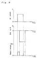
- the magnetic sensor 3 outputs an exclusive OR logic output only when either of the first and second currents I1 and I2 is applied, as shown in Fig. 9.
- first and second current I1 and I2 are determined to have different values for satisfying the conditions in this example, the conditions can be satisfied by adjusting distances between the first and second conductors 5 and 6 and the magnetic sensor 3 while keeping the first and second currents I1 and I2 at a constant value.
- the pattern layout for the magnetic sensor 3 and the first and second conductors 5 and 6 is not limited to that of the present preferred embodiment.
- the first and second linear conductors 5 and 6 can be arranged on both sides of the magnetic sensor 3, respectively.
- a protection film (not shown) of polyimide resin, SiO2 or the like which is formed on the magnetic sensor 3 to cover the same.
- a protective film 10 of polyimide, SiO2 or the like is formed on the magnetic sensor 3 and two linear conductors 5 and 6 are formed so as to cross the magnetic sensor 3 perpendicularly.
- the magnetic sensor 3 can output various logic outputs by controlling respective currents to be applied to the first and second linear electrodes 5 and 6.
- the conductors 5 and 6 and the ceramic superconductor 9 can be formed by a film of a ceramic superconductive material using the sputtering method MOCVD, the electron beam method or the like. These methods offer the possibility that patterns of the above mentioned elements can be made finely. It is also possible to make the conductors 5 and 6 using a superconductive ceramic material used for the magnetic sensor 3. In this case, the manufacturing process can be simplified since the conductors 5 and 6 are formed together with the superconductor 9 for the magnetic sensor 3.
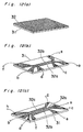
- Figs. 12(a) and 12(b) or 12(c) show an example wherein linear conductors are formed by patterning a ceramic superconductive film 32.
- the ceramic superconductive film 32 itself is formed according to the same method as stated above.
- the film 32 formed on a substrate 31, as shown in Fig. 12(a) is patterned by a suitable etching method, as shown in Fig. 12(b) or Fig. 12(c).
- the linear portion of the pattern 32a is used as a superconductor for the magnetic sensor and the linear portion of the pattern 32b is used as a linear conductor.
- the former pattern 32a has two current electrodes a and b and also two voltage electrodes c and d drawn out to respective sides of the substrate 31 and the latter pattern 32b has two electrodes e and f drawn out to respective corners of the substrate 31 for applying a control current to the linear conductor.
- the pattern shown in Fig. 12(c) is essentially the same as the structure of the superconductive logic device shown in Fig. 10. Namely, the pattern has first and second linear conductors 32b and 32c extending in parallel with a magnetic sensor 32a.
- the superconductive logic device operates as AND and EXCLUSIVE OR logic devices by controlling currents I1 and I2 as follows: If the currents I1 and I2 satisfy the following conditions; I1 ⁇ I0, I2 ⁇ I0, I1 + I2 > I0 (3) wherein I0 is a threshold current which gives the threshold magnetic field H0 and, if both of the currents I1 and I2 are applied to the first and second conductors 32b and 32c from the same direction, the magnetic sensor 32a outputs an AND logic output between the electrodes c and d as explained above with reference to Figs. 6 and 7.
- the superconductive logic device behaves as an exclusive OR logic device provided that the currents I1 and I2 satisfy the following conditions and that the directions of application of the currents I1 and I2 are mutually the same.
- portions of the film among the first and second conductors 32b and 32c and the magnetic sensor 32a are removed by etching in order to separate (insulate) each from the other electrically.
- electrical separation can also be attained by changing the electrical property of those portions from a conducting one to an insulating one.
- ions of As are implanted into portions of the film to be changed after covering the film with a metal mask having a pattern as shown in Fig. 12(b) or 12(c).
- a crystal structure of the ceramic superconductor is damaged by implanting As ions and is supposed to be changed into a non-crystal structure.
- the superconductive logic device manufactured using this method shows the same property as the superconductive logic device manufactured using the etching technique.
- the method for forming portions electrically separated is not limited to the above.
- a mechanical removal method such as the sand blast method, the photoetching method, the reforming method using diffusion of different elements or the like is also applicable.
- the ceramic superconductor to be used in the present invention is not limited to Y1Ba2Cu3O 7-x provided that it has random grain boundaries therein.
- Fig. 13 shows a superconductive logic device 1 according to the second preferred embodiment of the present invention.
- first and second linear ceramic superconductors 41 and 42 are formed in a lengthwise direction of a substrate 7 in series. Further, first and second control lines 46 and 47 are formed on the substrate 7 in series with each other and in parallel with the first and second superconductors 41 and 42, respectively.
- Respective outer ends of the first and second superconductors are connected to lead lines 43 and 45 forming terminals a and c at respective outer ends. Respective inner ends of them are connected by a lead line 44 of an inverted T-shape which forms a terminal b at its free end.
- first and second control lines 46 and 47 are connected to lead lines 48 and 50 forming terminals d and f at respective free ends and a lead line 49 of a T-shape forming a terminal e at its lower end is connected between them.
- Fig. 14 shows an inverter logic circuit using the superconductive logic device 1 shown in Fig. 13.
- the first and second superconductors 41 and 42 are represented by variable resistance R1 and R2, respectively and the first and second control lines 46 and 47 are represented by magnetic coils, respectively.
- the terminal a is connected to a voltage supply source of a standard voltage Vcc and the terminal c is connected to the ground GND.
- the terminals d and f are connected, via resistances r1 and r2, to the ground GND and the voltage supply source, respectively.
- An input voltage V IN is applied to the terminal e and an output voltage V OUT is taken out at the terminal b of a first inverter logic circuit and those of a second inverter logic circuit are connected in series between V OUT and GND.
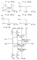
- Fig. 16 shows a NAND logic circuit which comprises two inverter logic circuits each of which is shown in Fig. 14.
- the first and second superconductors 41-1 and 41-2 of the first inverter circuit are connected in parallel between Vcc and V OUT
- the first and second superconductors 42-1 and 42-2 of the second inverter circuit are connected in series between V OUT and the ground GND
- output terminals of the two inverter logic circuits are connected with each other so as to output an output voltage V OUT and input voltages V IN1 and V IN2 are input to input terminals of them, respectively.
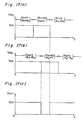
- Fig. 18 shows a NOR logic circuit obtained by changing the connection relations of the NAND logic circuit shown in Fig. 16.
- the first and second superconductors 41-1 and 41-2 of the first inverter circuit are connected in series between Vcc and V OUT and those 42-1 and 42-2 of the second inverter circuit are connected in parallel between V OUT and GND in the former.
- V OUT drops down to zero during application of V IN1 or V IN2 of a high level as shown in Fig. 19(a) or 19(b).
- a NOR logic output is obtained.
- a desired NAND or NOR logic signal can be obtained even if the superconductors have the resistance R0 simultaneously in the case that the threshold current I0 becomes lower than Vcc/2r0 .
- a complementary type superconductive logic circuit wherein a desired logic output V OUT can be obtained in accordance with values of the input currents V IN1 and V IN2 with the use of a stabilized voltage power supply.
- Fig. 20 shows an AND logic device 1 using an elongated thin superconductor 3.
- a pair of current electrodes 11 and 11 and a pair of voltage electrodes 13 and 13 are formed on respective end portions of the superconductor 3.
- Two current feeding means (not shown explicitly) for feeding currents I1 and I2 are connected to either one of lead lines 15 and 15 connecting respective current electrodes 11 and 11.
- a constant magnetic field H is applied to the superconductor 3 vertically thereto.
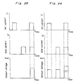
- Fig. 21 shows a magneto-resistive property of the superconductor 3 and Fig. 22 shows a relation between a threshold value Hth of the magnetic field to be applied to the superconductor 3 and a current to be fed thereto.
- the superconductor 3 has a resistance to generate an output voltage V OUT between two voltage electrodes 13 and 13 as shown in Fig. 23.
- the superconductive logic device 1 functions as an AND logic device.
- the superconductive logic device functions as an OR logic device as shown in Fig. 24.
- the magnetic field can be applied to the superconductor 3 using an electric magnet.
- the strength of the magnetic field can be controlled by controlling a current applied to the magnet.
- the logic device can function as both AND and OR logic devices by changing the strength of the magnetic field.
- Fig. 25 shows a superconductive logic unit 101 according to the fourth preferred embodiment of the present invention.
- An elongated thin superconductor 102 is formed on a surface of a substrate 103 along a lengthwise centre line thereof.
- a control line 104 of the same superconductive material as the superconductor 102 is formed in the lengthwise direction of the substrate 103.
- the substrate 103 can be made of a non-magnetic material such as stabilized zirconia, magnesia or the like.
- the superconductor 102 and the control line 104 are made using the same method as in the first preferred embodiment.
- composition of the superconductive logic unit 101 is symbolized as shown in Fig. 26 for simplicity sake.
- Fig. 27(a) shows a fundamental logic circuit using the superconductive logic unit.
- the superconductor 102 is connected between a reference voltage line of a positive voltage Vcc and the ground in series with a resistance R.
- One end of the control line 104 is connected to the ground and the other end thereof is used as an input terminal I for inputting a control signal.
- An output terminal O is drawn out from a portion between the superconductor 102 and the resistance R.
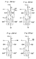
- Fig. 28(a) shows an AND logic circuit using two superconductive logic units.
- two control lines 104 and 104' are connected to input terminals A and B to which positive signal voltages are inputted, respectively and two superconductors 102 and 102' are connected in parallel between a resistance R connected to a standard power supply of a positive voltage (+Vcc) and the ground.
- a common output terminal A ⁇ B is drawn out from a portion between the resistance R and the superconductor 102 and from the other end of another superconductor 102'.
- this logic circuit forms an AND logic circuit.
- Fig. 28(b) shows a NAND circuit using two superconductive logic units.
- the standard power supply feeds a negative standard voltage (-Vcc) while maintaining other connection relations same as those of Fig. 28(a).
- an inverted output voltage (-V OUT ) is generated at an output terminal A ⁇ B only when control signals are inputted to both of the input terminals A and B simultaneously.
- Fig. 29(a) shows an OR logic circuit using two superconductive logic circuits.
- two superconductors 102 and 102' are connected in series, via a resistance R, between a standard voltage supply of a positive voltage Vcc and the ground, while respective control lines 104 and 104' are connected to respective input terminals A and B.
- An output terminal (A + B) is drawn out from a portion between the resistance R and the superconductor 102.
- this logic circuit forms an OR logic circuit.
- Fig. 29(b) shows a NOR logic circuit using two superconductive logic units.
- the resistance R is connected to a standard voltage supply of a negative voltage (-Vcc) in this logic circuit and, therefore, an inverted OR output voltage (-V OUT ) is outputted at the output terminal (A + B) .
- a superconductive logic unit 101 having a control line 104 and a line 106 can be made of a ceramic superconductive material using the same forming method as of a superconductor 102 to be formed on another surface of a surface of a substrate 103.
- a constant current is always applied to the line 106 to exert a bias magnetic field to the superconductor 102.
- the bias magnetic field H B is set so as to have a strength relatively close to but lower than the threshold magnetic field H C . Due to this, the superconductor 102 can show a quick response to a control signal to be applied to the control line 104 even if the control signal is too weak to generate a resistance in the superconductor 102 only by itself.
- control line and/or the bias line are formed on the rear surface of the substrate in the third preferred embodiment, they can be formed together with the superconductor on the same surface of the substrate as stated in the foregoing preferred embodiment.
- Fig. 31 shows a plan view of a superconductive logic device according to the fifth embodiment of the present invention.
- This superconductive logic device 51 comprises a superconductor 52 formed on a substrate 53 and a control line 54 of an inverted U shape which is formed on an insulation film 55 for insulating the superconductor 52 from the control line 54.
- the superconductor 52 has a pair of current electrodes 56 and 56 for applying a constant current and also a pair of voltage electrodes 57 and 57 for detecting an output voltage. If no current is supplied to the control line 54 no voltage is detected between terminals c and d. However, if a control current is applied to the control line 54, an output voltage V OUT is generated between terminals c and d since a resistance is generated in the superconductor 3 by a magnetic field generated by the control current.
- the dimensions of the superconductor 52 are set same as those of the superconductor 3 shown in Fig. 1 and the width of the control line 54 is set at 30 ⁇ ms. In this case, if a control current of 5 mAs is applied to the control line 54 while applying a constant current of about 1 mA to the superconductor 52, an output voltage V OUT of about 20 ⁇ Vs is generated between terminals c and d.
- a constant current of about 10 mAs to the superconductor 53 in order to obtain an output voltage between terminals c and d.
- the constant current can be decreased to 1 mA since the control line crosses over the superconductor 52 twice and, therefore, magnetic fields generated by respective portions of the control line 54 are applied concentratedly to the superconductor 42. Also, the strength of the control current is decreased to several mAs as stated above.
- one more control line 58 having terminals g and h is formed on the substrate 53 substantially in parallel with the superconductor 52.
- the middle portion 58a of the control line 58 is formed close to portion 54a of the control line 54 parallel to the superconductor 52.
- a distance between respective centres of the portions 58a and 54a is set at 50 ⁇ ms.
- the widths of two control lines and the superconductor 52 are set at 30 ⁇ ms, 30 ⁇ ms and 50 ⁇ ms, respectively.
- current I1 and I2 are set so as to satisfy the following conditions: H1 ⁇ H2, H2 ⁇ H0, H1 + H2 > H0 wherein H0 is a threshold magnetic field from which a resistance is generated in the superconductor 52 when a predetermined current is applied thereto, and H1 and H2 are magnetic fields applied thereto by respective currents I1 and I2.
- H0 is a threshold magnetic field from which a resistance is generated in the superconductor 52 when a predetermined current is applied thereto
- H1 and H2 are magnetic fields applied thereto by respective currents I1 and I2.
- no output voltage is detected between terminals c and d when either of the currents I1 an I2 is applied to either of the two control lines 54 and 58.
- an output voltage V OUT is generated between terminals c and d only when both of the currents I1 and I2 are applied in the same direction as indicated by arrows.
- the currents I1 and I2 are set at 3 mAs and 15 m
- composition of this logic circuit is essentially same to that of the logic circuit shown in Fig. 6. However, it is to be noted that, according to the present preferred embodiment, an output voltage V OUT having a same height as that of the logic circuit shown in Fig. 6 is obtained with weaker currents than those of the latter.
- the superconductive logic device functions as an OR logic circuit. Namely, if only one current I1 or I2 is applied to the corresponding control line, an output voltage V OUT is generated between terminals c and d. However, if both of the currents I1 and I2 are applied to both of the control lines 54 and 58 simultaneously but in opposite directions to each other, no output voltage V OUT is detected, as shown in Fig. 33.
- Fig. 34 shows a variation of the superconductive logic circuit shown in Fig. 32.
- a first control line 54' is formed in a U-shape having two parallel portions 54'a and 54'b extending in parallel with the elongated superconductor 52 and a connection portion 54'c is formed on an insulation film 55' crossing over the superconductor 52.
- a second control line 58 is formed in parallel with the portion 54'b of the first control line 54'.
- this superconductive logic circuit Since the essential structure of this superconductive logic circuit is identical with that of the logic circuit shown in Fig. 32, it functions as both AND and OR circuits by controlling the strengths and relative directions of the currents I1 and I2.
Landscapes
- Superconductor Devices And Manufacturing Methods Thereof (AREA)
Claims (15)
- Logikbauteil umfassend:
einen supraleitenden Körper, der magnetoresistive Eigenschaften zeigt, wenn er im wesentlichen bei seiner kritischen Temperatur gehalten wird;
Einrichtung zum Anlegen eines konstanten elektrischen Stromes an den supraleitenden Körper;
Leitereinrichtung, die im Bereich da supraleitenden Körpers eingerichtet und von diesem elektrisch isoliert ist, um in Abhängigkeit eines durch die Leitereinrichtung fließenden elektrischen Stromes ein Magnetfeld an den supraleitenden Körper anzulegen; und
Einrichtung zum Ermitteln der Auswirkung von einem oder mehreren Signalströmen in der Leitereinrichtung auf den Widerstand des supraleitenden Körpers, dadurch gekennzeichnet, daß:
der supraleitende Körper ein längliches Dünnfilm-Keramikmaterial mit zufälligen Korngrenzen, die als lose Kopplungen wirken, umfaßt, wobei der längliche Dünnfilm auf einem elektrisch isolierenden Substrat gebildet ist, und dadurch daß:
die Leitereinrichtung mindestens einen auf dem Substrat gebildeten Dünnfilm-Streifenleiter umfaßt, wobei sich der Streifenleiter mit mindestens einem Teil parallel zu der Längenausdehnung des supraleitenden Körpers erstreckt. - Logikbauteil nach Anspruch 1, worin der supraleitende Körper und die Leitereinrichtung auf der gleichen Seite des Substrats gebildet sind.
- Logikbauteil nach Anspruch 2, worin ein Teil von mindestens einem der Streifenleiter den supraleitenden Körper kreuzt.
- Logikbauteil nach Anspruch 2 oder 3, worin die Leitereinrichtung zwei der Streifenleiter umfaßt, die voneinder elektrisch isoliert sind.
- Logikbauteil nach Anspruch 4 in Verbindung mit Anspruch 2, worin die zwei Streifenleiter auf der gleichen Seite des supraleitenden Körpers gebildet sind.
- Logikbauteil nach Anspruch 4 in Verbindung mit Anspruch 2, worin die zwei Streifenleiter auf gegenüberliegenden Seiten des supraleitenden Körpers gebildet sind.
- Logikbauteil nach einem der Ansprüche 4 bis 6, worin betreffende Signalströme I₁ und I₂, die an die zwei Streifenleiter angelegt sind, die folgenden Bedingungen erfüllen:


und
worin I₀ ein Schwellenstrom ist, der ein Schwellenmagnetfeld erzeugt, um den Widerstand des supraleitenden Körpers zu verändern. - Logikbauteil nach einem der Ansprüche 4 bis 6, worin betreffende Signalströme I₁ und I₂, die an die zwei Streifenleiter angelegt sind, die folgenden Bedingungen erfüllen:


und
worin I₀ ein Schwellenstrom ist, der ein Schwellenmagnetfeld erzeugt, um den Widerstand des supraleitenden Körpers zu verändern. - Logikbauteil nach einem der Ansprüche 4 bis 6, worin einer von den zwei Streifenleitern einen konstanten Strom führt, um ein Vorspannungsmagnetfeld an den supraleitenden Körper anzulegen.
- Logikbauteil nach einem der Ansprüche 2 bis 9, worin die Leitereinrichtung aus dem gleichen keramischen Material gebildet ist wie der supraleitende Körper.
- Logikbauteil nach einem der vorangehenden Ansprüche, worin die Einrichtung zum Anlegen eines Stromes ein erstes Paar von Elektroden umfaßt, die mit betreffenden gegenüberliegenden Enden des supraleitenden Körpers verbunden sind, und die Einrichtung zum Ermitteln ein zweites Paar von Elektroden umfaßt, die eingerichtet sind, um eine in dem supraleitenden Körper erzeugte Spannung zu ermitteln.
- Logikbauteil nach Anspruch 11 in Verbindung mit Anspruch 10, worin die ersten und zweiten Elektrodenpaare als Dünnfilm-Streifenleiter aus dem gleichen keramischen Material gebildet sind wie der supraleitende Körper.
- Verfahren zur Herstellung des Logikbauteils von Anspruch 12 umfassend die Schritte zum Bilden einer Dünnfilmschicht aus einem supraleitenden keramischen Material auf einer Seite eines elektrisch isolierenden Substrats, und Versehen der Dünnfilmschicht mit einem Muster, um den supraleitenden Körper, die Leitereinrichtung und die ersten und zweiten Elektrodenpaare zu bestimmen.
- Verfahren nach Anspruch 13, worin der Schritt zum Versehen mit einem Muster ein Ätzen der Dünnfilmschicht umfaßt.
- Verfahren nach Anspruch 13, worin der Schritt zum Versehen mit einem Muster eine Ionenimplantation der Dünnfilmschicht umfaßt.
Applications Claiming Priority (16)
| Application Number | Priority Date | Filing Date | Title |
|---|---|---|---|
| JP29526/88 | 1988-02-10 | ||
| JP2952688 | 1988-02-10 | ||
| JP63081993A JPH0810770B2 (ja) | 1988-02-10 | 1988-03-31 | セラミック超電導装置 |
| JP81993/88 | 1988-03-31 | ||
| JP108773/88 | 1988-04-30 | ||
| JP63108773A JPH01278123A (ja) | 1988-04-30 | 1988-04-30 | 相補型超電導回路 |
| JP117471/88 | 1988-05-13 | ||
| JP63117471A JPH081968B2 (ja) | 1988-05-13 | 1988-05-13 | セラミック超電導装置 |
| JP134797/88 | 1988-05-31 | ||
| JP63134794A JPH01303767A (ja) | 1988-05-31 | 1988-05-31 | 超電導論理装置 |
| JP134798/88 | 1988-05-31 | ||
| JP63134798A JPH0810771B2 (ja) | 1988-05-31 | 1988-05-31 | 超電導論理回路 |
| JP63134797A JPH01303768A (ja) | 1988-05-31 | 1988-05-31 | 超電導論理素子 |
| JP134794/88 | 1988-05-31 | ||
| JP63202351A JPH0810772B2 (ja) | 1988-02-10 | 1988-08-12 | セラミック超電導装置 |
| JP202351/88 | 1988-08-12 |
Publications (3)
| Publication Number | Publication Date |
|---|---|
| EP0328398A2 EP0328398A2 (de) | 1989-08-16 |
| EP0328398A3 EP0328398A3 (en) | 1990-11-14 |
| EP0328398B1 true EP0328398B1 (de) | 1993-04-21 |
Family
ID=27572087
Family Applications (1)
| Application Number | Title | Priority Date | Filing Date |
|---|---|---|---|
| EP89301279A Expired - Lifetime EP0328398B1 (de) | 1988-02-10 | 1989-02-10 | Supraleitende logische Vorrichtung |
Country Status (4)
| Country | Link |
|---|---|
| US (1) | US5298485A (de) |
| EP (1) | EP0328398B1 (de) |
| CN (1) | CN1054471C (de) |
| DE (1) | DE68906044T2 (de) |
Families Citing this family (4)
| Publication number | Priority date | Publication date | Assignee | Title |
|---|---|---|---|---|
| US5051627A (en) * | 1989-12-29 | 1991-09-24 | Trw Inc. | Superconducting nonhysteretic logic design |
| SE512591C2 (sv) * | 1995-06-30 | 2000-04-10 | Ericsson Telefon Ab L M | Anordning och förfarande avseende digital information |
| KR20040094598A (ko) * | 2002-04-03 | 2004-11-10 | 소니 가부시끼 가이샤 | 집적회로, 집적회로장치, 집적회로장치의 구성방법 및집적회로장치의 제조방법 |
| JP5270176B2 (ja) * | 2008-01-08 | 2013-08-21 | 公益財団法人国際超電導産業技術研究センター | Re系酸化物超電導線材及びその製造方法 |
Family Cites Families (18)
| Publication number | Priority date | Publication date | Assignee | Title |
|---|---|---|---|---|
| US3365584A (en) * | 1968-01-23 | Gen Electric | Cryo-electronic threshold components | |
| FR1205568A (fr) * | 1957-05-14 | 1960-02-03 | Ibm | Dispositifs à superconduction traitant des informations et utilisant des écrans magnétiques |
| US3171035A (en) * | 1958-05-26 | 1965-02-23 | Bunker Ramo | Superconductive circuits |
| US2938160A (en) * | 1958-06-11 | 1960-05-24 | Rca Corp | Switching devices |
| US3076102A (en) * | 1958-09-02 | 1963-01-29 | Gen Electric | Cryogenic electronic gating circuit |
| US3093754A (en) * | 1960-06-03 | 1963-06-11 | Space Technology Lab Inc | Superconductor and gate employing single elongated, simply connected thin film as gate element |
| US3182275A (en) * | 1960-12-16 | 1965-05-04 | Gen Electric | Asymmetric cryogenic device |
| NL272628A (de) * | 1960-12-19 | |||
| US3145310A (en) * | 1961-08-23 | 1964-08-18 | Ibm | Superconductive in-line gating devices and circuits |
| NL300191A (de) * | 1962-11-29 | |||
| US3255362A (en) * | 1962-12-10 | 1966-06-07 | Burroughs Corp | Cryotron logic circuits having at least two interacting central elements and one path always superconducting |
| DE1205144B (de) * | 1963-07-25 | 1965-11-18 | Int Computers & Tabulators Ltd | Anordnung zur Umschaltung der Induktivitaet eines Gatterleiters zwischen zwei Extremwerten |
| GB1053476A (de) * | 1963-10-09 | |||
| US3369127A (en) * | 1964-05-26 | 1968-02-13 | Westinghouse Electric Corp | Cryogenic universal logic element |
| US4097765A (en) * | 1976-06-30 | 1978-06-27 | International Business Machines Corporation | Electronically alterable non-latching Josephson AND, OR, NAND, NOR logic circuit |
| US4316785A (en) * | 1979-11-05 | 1982-02-23 | Nippon Telegraph & Telephone Public Corporation | Oxide superconductor Josephson junction and fabrication method therefor |
| JPS6065582A (ja) * | 1983-09-20 | 1985-04-15 | Nippon Telegr & Teleph Corp <Ntt> | 粒界ジヨセフソン接合型光検出素子 |
| DE3815183A1 (de) * | 1987-08-20 | 1989-03-02 | Siemens Ag | Supraleitendes gatterelement fuer eine logische schaltung |
-
1989
- 1989-02-10 CN CN89101727A patent/CN1054471C/zh not_active Expired - Fee Related
- 1989-02-10 EP EP89301279A patent/EP0328398B1/de not_active Expired - Lifetime
- 1989-02-10 DE DE89301279T patent/DE68906044T2/de not_active Expired - Fee Related
-
1992
- 1992-11-30 US US07/983,290 patent/US5298485A/en not_active Expired - Fee Related
Also Published As
| Publication number | Publication date |
|---|---|
| CN1036673A (zh) | 1989-10-25 |
| US5298485A (en) | 1994-03-29 |
| DE68906044T2 (de) | 1993-11-04 |
| DE68906044D1 (de) | 1993-05-27 |
| CN1054471C (zh) | 2000-07-12 |
| EP0328398A3 (en) | 1990-11-14 |
| EP0328398A2 (de) | 1989-08-16 |
Similar Documents
| Publication | Publication Date | Title |
|---|---|---|
| EP0654802B1 (de) | Variables induktives Element | |
| HK1007860B (en) | Variable inductance element | |
| US5376624A (en) | Josephson break junction thin film device | |
| WO1998007165A3 (en) | Magnetic current sensor | |
| WO1990014715A1 (en) | Magnetic effect transistor | |
| EP0328398A2 (de) | Supraleitende logische Vorrichtung | |
| US3097336A (en) | Semiconductor voltage divider devices | |
| EP0444873B1 (de) | Gerät zum Messen der Magnetfeldverteilung | |
| JPH03228384A (ja) | 超電導素子 | |
| US3047744A (en) | Cryoelectric circuits employing superconductive contact between two superconductive elements | |
| EP0381541B1 (de) | Supraleitende magnetoresistive Anordnung | |
| JPH02271685A (ja) | 超伝導三端子素子およびその製造方法 | |
| JP3284293B2 (ja) | 酸化物超伝導ジョセフソン接合アレイ素子およびその製造方法 | |
| JPH081969B2 (ja) | セラミック超電導装置 | |
| JPH01302784A (ja) | セラミック超電導装置 | |
| US7105911B2 (en) | Multilayer electronic substrate, and the method of manufacturing multilayer electronic substrate | |
| JPS58147783A (ja) | 液晶表示装置 | |
| JPS6468961A (en) | Resistance element for semiconductor integrated circuit device | |
| Jeffreys et al. | The electroluminescent matrix for pattern display and recording | |
| KR100273166B1 (ko) | 부온도계수 서미스터 | |
| JPS6167974A (ja) | 超伝導回路装置 | |
| SU398160A1 (ru) | Полупроводниковый прибор | |
| EP0881684A1 (de) | Widerstandsstruktur für integrierte Schaltung | |
| US7914915B2 (en) | Highly charged ion modified oxide device and method of making same | |
| CA1115792A (en) | Direct current transformer |
Legal Events
| Date | Code | Title | Description |
|---|---|---|---|
| PUAI | Public reference made under article 153(3) epc to a published international application that has entered the european phase |
Free format text: ORIGINAL CODE: 0009012 |
|
| 17P | Request for examination filed |
Effective date: 19890302 |
|
| AK | Designated contracting states |
Kind code of ref document: A2 Designated state(s): CH DE FR GB IT LI NL |
|
| PUAL | Search report despatched |
Free format text: ORIGINAL CODE: 0009013 |
|
| RHK1 | Main classification (correction) |
Ipc: H01L 39/18 |
|
| AK | Designated contracting states |
Kind code of ref document: A3 Designated state(s): CH DE FR GB IT LI NL |
|
| 17Q | First examination report despatched |
Effective date: 19911227 |
|
| GRAA | (expected) grant |
Free format text: ORIGINAL CODE: 0009210 |
|
| AK | Designated contracting states |
Kind code of ref document: B1 Designated state(s): CH DE FR GB IT LI NL |
|
| REF | Corresponds to: |
Ref document number: 68906044 Country of ref document: DE Date of ref document: 19930527 |
|
| ET | Fr: translation filed | ||
| ITF | It: translation for a ep patent filed | ||
| PLBE | No opposition filed within time limit |
Free format text: ORIGINAL CODE: 0009261 |
|
| STAA | Information on the status of an ep patent application or granted ep patent |
Free format text: STATUS: NO OPPOSITION FILED WITHIN TIME LIMIT |
|
| 26N | No opposition filed | ||
| REG | Reference to a national code |
Ref country code: GB Ref legal event code: IF02 |
|
| PGFP | Annual fee paid to national office [announced via postgrant information from national office to epo] |
Ref country code: FR Payment date: 20020212 Year of fee payment: 14 |
|
| PGFP | Annual fee paid to national office [announced via postgrant information from national office to epo] |
Ref country code: GB Payment date: 20020213 Year of fee payment: 14 |
|
| PGFP | Annual fee paid to national office [announced via postgrant information from national office to epo] |
Ref country code: CH Payment date: 20020214 Year of fee payment: 14 |
|
| PGFP | Annual fee paid to national office [announced via postgrant information from national office to epo] |
Ref country code: DE Payment date: 20020227 Year of fee payment: 14 |
|
| PGFP | Annual fee paid to national office [announced via postgrant information from national office to epo] |
Ref country code: NL Payment date: 20020228 Year of fee payment: 14 |
|
| PG25 | Lapsed in a contracting state [announced via postgrant information from national office to epo] |
Ref country code: GB Free format text: LAPSE BECAUSE OF NON-PAYMENT OF DUE FEES Effective date: 20030210 |
|
| PG25 | Lapsed in a contracting state [announced via postgrant information from national office to epo] |
Ref country code: LI Free format text: LAPSE BECAUSE OF NON-PAYMENT OF DUE FEES Effective date: 20030228 Ref country code: CH Free format text: LAPSE BECAUSE OF NON-PAYMENT OF DUE FEES Effective date: 20030228 |
|
| PG25 | Lapsed in a contracting state [announced via postgrant information from national office to epo] |
Ref country code: NL Free format text: LAPSE BECAUSE OF NON-PAYMENT OF DUE FEES Effective date: 20030901 |
|
| PG25 | Lapsed in a contracting state [announced via postgrant information from national office to epo] |
Ref country code: DE Free format text: LAPSE BECAUSE OF NON-PAYMENT OF DUE FEES Effective date: 20030902 |
|
| GBPC | Gb: european patent ceased through non-payment of renewal fee | ||
| REG | Reference to a national code |
Ref country code: CH Ref legal event code: PL |
|
| PG25 | Lapsed in a contracting state [announced via postgrant information from national office to epo] |
Ref country code: FR Free format text: LAPSE BECAUSE OF NON-PAYMENT OF DUE FEES Effective date: 20031031 |
|
| NLV4 | Nl: lapsed or anulled due to non-payment of the annual fee |
Effective date: 20030901 |
|
| REG | Reference to a national code |
Ref country code: FR Ref legal event code: ST |
|
| PG25 | Lapsed in a contracting state [announced via postgrant information from national office to epo] |
Ref country code: IT Free format text: LAPSE BECAUSE OF NON-PAYMENT OF DUE FEES;WARNING: LAPSES OF ITALIAN PATENTS WITH EFFECTIVE DATE BEFORE 2007 MAY HAVE OCCURRED AT ANY TIME BEFORE 2007. THE CORRECT EFFECTIVE DATE MAY BE DIFFERENT FROM THE ONE RECORDED. Effective date: 20050210 |