EP0327785B1 - Verfahren zum Steuern einer Wärmequelle - Google Patents
Verfahren zum Steuern einer Wärmequelle Download PDFInfo
- Publication number
- EP0327785B1 EP0327785B1 EP88730028A EP88730028A EP0327785B1 EP 0327785 B1 EP0327785 B1 EP 0327785B1 EP 88730028 A EP88730028 A EP 88730028A EP 88730028 A EP88730028 A EP 88730028A EP 0327785 B1 EP0327785 B1 EP 0327785B1
- Authority
- EP
- European Patent Office
- Prior art keywords
- control
- gas valve
- gas
- fan
- heat source
- Prior art date
- Legal status (The legal status is an assumption and is not a legal conclusion. Google has not performed a legal analysis and makes no representation as to the accuracy of the status listed.)
- Expired - Lifetime
Links
Images
Classifications
-
- F—MECHANICAL ENGINEERING; LIGHTING; HEATING; WEAPONS; BLASTING
- F23—COMBUSTION APPARATUS; COMBUSTION PROCESSES
- F23N—REGULATING OR CONTROLLING COMBUSTION
- F23N5/00—Systems for controlling combustion
- F23N5/24—Preventing development of abnormal or undesired conditions, i.e. safety arrangements
- F23N5/242—Preventing development of abnormal or undesired conditions, i.e. safety arrangements using electronic means
-
- F—MECHANICAL ENGINEERING; LIGHTING; HEATING; WEAPONS; BLASTING
- F23—COMBUSTION APPARATUS; COMBUSTION PROCESSES
- F23N—REGULATING OR CONTROLLING COMBUSTION
- F23N1/00—Regulating fuel supply
- F23N1/06—Regulating fuel supply conjointly with draught
- F23N1/062—Regulating fuel supply conjointly with draught using electronic means
-
- F—MECHANICAL ENGINEERING; LIGHTING; HEATING; WEAPONS; BLASTING
- F23—COMBUSTION APPARATUS; COMBUSTION PROCESSES
- F23N—REGULATING OR CONTROLLING COMBUSTION
- F23N2225/00—Measuring
- F23N2225/04—Measuring pressure
- F23N2225/06—Measuring pressure for determining flow
-
- F—MECHANICAL ENGINEERING; LIGHTING; HEATING; WEAPONS; BLASTING
- F23—COMBUSTION APPARATUS; COMBUSTION PROCESSES
- F23N—REGULATING OR CONTROLLING COMBUSTION
- F23N2225/00—Measuring
- F23N2225/08—Measuring temperature
- F23N2225/18—Measuring temperature feedwater temperature
-
- F—MECHANICAL ENGINEERING; LIGHTING; HEATING; WEAPONS; BLASTING
- F23—COMBUSTION APPARATUS; COMBUSTION PROCESSES
- F23N—REGULATING OR CONTROLLING COMBUSTION
- F23N2231/00—Fail safe
- F23N2231/10—Fail safe for component failures
-
- F—MECHANICAL ENGINEERING; LIGHTING; HEATING; WEAPONS; BLASTING
- F23—COMBUSTION APPARATUS; COMBUSTION PROCESSES
- F23N—REGULATING OR CONTROLLING COMBUSTION
- F23N2233/00—Ventilators
- F23N2233/02—Ventilators in stacks
- F23N2233/04—Ventilators in stacks with variable speed
-
- F—MECHANICAL ENGINEERING; LIGHTING; HEATING; WEAPONS; BLASTING
- F23—COMBUSTION APPARATUS; COMBUSTION PROCESSES
- F23N—REGULATING OR CONTROLLING COMBUSTION
- F23N2235/00—Valves, nozzles or pumps
- F23N2235/12—Fuel valves
- F23N2235/14—Fuel valves electromagnetically operated
-
- F—MECHANICAL ENGINEERING; LIGHTING; HEATING; WEAPONS; BLASTING
- F23—COMBUSTION APPARATUS; COMBUSTION PROCESSES
- F23N—REGULATING OR CONTROLLING COMBUSTION
- F23N2235/00—Valves, nozzles or pumps
- F23N2235/12—Fuel valves
- F23N2235/16—Fuel valves variable flow or proportional valves
-
- F—MECHANICAL ENGINEERING; LIGHTING; HEATING; WEAPONS; BLASTING
- F23—COMBUSTION APPARATUS; COMBUSTION PROCESSES
- F23N—REGULATING OR CONTROLLING COMBUSTION
- F23N5/00—Systems for controlling combustion
- F23N5/02—Systems for controlling combustion using devices responsive to thermal changes or to thermal expansion of a medium
- F23N5/12—Systems for controlling combustion using devices responsive to thermal changes or to thermal expansion of a medium using ionisation-sensitive elements, i.e. flame rods
Definitions
- the present invention relates to a method for controlling a circulating water heater according to the preamble of the claim.
- a method for controlling a circulating water heater in the gas line of which two gas valves are arranged.
- the first is operated by a control and regulating device in proportional operation, the second is kept open hydraulically even when a pump of the central heating generates a differential pressure, which indicates a water throughput in the circulating water heater.
- a flame ionization sensor an exhaust gas fan, a differential pressure sensor in the supply air line, an automatic burner control, which is part of the control and regulating device, and an ignition device for the burner.
- the circulating water heater is operated so that when a switch-on control command is present, the motor of the circulating pump is first supplied with voltage.
- the circulation pump starts up, and due to the water throughput there is a differential pressure and thus a signal, which leads to the opening of one gas valve leads.
- the control and regulating device applies voltage to the motor of the exhaust gas fan, so that it starts up.
- the sealed combustion chamber of the circulating water heater is flushed with fresh air, the throughput of fresh air is measured at the differential pressure sensor in the supply air path and reported back to the control and regulating device.
- the ignition is released, which means that the other gas valve also receives an opening command so that the gas line to the burner is open; at the same time the main burner is ignited. After a flame has been formed, the existence of this flame is reported back to the control and regulating device by the ionization sensor. This means that the circulation water heater is operating correctly. If the flow temperature reaches the target value, a control shutdown takes place, which means that one of the two gas valves is de-energized and closes. A run-on time can result for the exhaust gas fan, likewise for the circulation pump, so that the other gas valve does not necessarily have to close.
- the present invention is therefore based on the object of preventing this unsanitary operation.
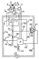
- a circulating water heater 1 has a sealed combustion chamber 2, in which a heat exchanger 3 and a gas burner 4 are arranged.
- the combustion chamber 2 communicates with the atmosphere via a concentric double tube 5, an annular gap 6 between an inner tube 7 and an outer tube 8 defining a fresh air path, while the exhaust gas path 9 is formed by the cross section of the inner tube, in which an exhaust gas fan 10 is arranged, which is driven by a motor 11.
- a differential pressure sensing point 13 is arranged in the annular supply air path 12 and is connected to a control or regulating device 15 via a measuring line 14.
- the heat exchanger 3 is connected to a flow line 16 which is provided with a flow temperature sensor 17 which is connected to the control or regulating device 15 via a measuring line 18.
- a consumer 19 in the form of a plurality of radiators or a domestic hot water tank connected in series or in parallel is connected to the feed line 16.
- a return line 20 is provided between the consumer 19 and the heat exchanger 3, into which a circulation pump 21 is switched on, into which a drive motor is integrated, which is connected to the control or regulating device 15 with an electrical supply line 22.
- From the pump supply and return connection leads - after Type of water shortage protection - each a pressure measuring line 23 or 24 to a differential pressure measuring device 25, which transmits the pressure difference to an actuating rod 26 which is connected directly to a valve body of a second gas valve 27.
- This gas valve 27 lies in the course of a gas line 28, in series with a first gas valve 29, which is connected to the control or regulating device 15 via a control line 30.
- the electromagnetic servomotor for the first gas valve 29 is integrated in this gas valve 29.
- An ionization flame detector 31 is assigned to the burner 4 and is connected to the control or regulating device 15 via a measuring line 32.
- the drive motor 11 of the fan 10 is connected to the control or regulating device 15 via a control line 33, just like a target value transmitter 34 via a line 35.
- the method for controlling this circulating water heater 1 normally works exactly as in the prior art provided for this invention.
- a shutdown command results. That is, the electromagnet of the first gas valve 29 is de-energized. Since the sticking of the valve body is assumed, the burner 4 remains supplied with gas from the gas line 28, that is to say the flame continues to burn. The ionization detector 31 reports this burning flame to the control or regulating device 15. It is assumed that the control and regulating device 15 does not automatically switch off the circulation pump 21 when the control shutdown command is given.
- the circulation pump 21 can instead be switched off via a room temperature sensor or can be effected in some other way.
- the safety temperature limiter which is required anyway, is present with its shutdown mechanism; but is not mentioned here because it does not contribute to the invention. However, he could control both gas valves 27 and 29. This safety shutdown is also locking.
Description
- Die vorliegende Erfindung bezieht sich auf ein Verfahren zum Steuern eines Umlaufwasserheizers gemäß dem Oberbegriff des Patentanspruchs.
- Es ist ein Verfahren zum Steuern eines Umlaufwasserheizers bekannt, in dessen Gasleitung zwei Gasventile angeordnet sind. Das erste wird von einer Steuer- und Regeleinrichtung im Proportionalbetrieb betrieben, das zweite wird hydraulisch auch dann offengehalten, wenn eine Pumpe der Zentralheizung einen Differenzdruck erzeugt, der auf einen Wasserdurchsatz im Umlaufwasserheizer schließen läßt. Weiterhin sind ein Flammenionisationsfühler, ein Abgasventilator, eine Differenzdruck-Fühlstelle in der Zuluftleitung, ein Feuerungsautomat, der Teil der Steuer- und Regeleinrichtung ist, und eine Zündeinrichtung für den Brenner vorhanden.
- Nach dem bekannten Verfahren wird der Umlaufwasserheizer so betrieben, daß beim Vorliegen eines Einschaltregelbefehls zunächst der Motor der Umwälzpumpe mit Spannung versorgt wird. Die Umwälzpumpe läuft an, und es entsteht aufgrund des Wasserdurchsatzes ein Differenzdruck und damit ein Signal, was zum Öffnen des einen Gasventils führt. Parallel hierzu wird von der Steuer- und Regeleinrichtung der Motor des Abgasventilators mit Spannung beaufschlagt, so daß dieser anläuft. Die dichte Brennkammer des Umlaufwasserheizers wird mit Frischluft gespült, der Durchsatz an Frischluft wird an der Differenzdruck-Fühlstelle im Zuluftweg gemessen und auf die Steuer- und Regeleinrichtung rückgemeldet. Wird ordnungsgemäßer Luftdurchsatz gemeldet, wird die Zündung freigegeben, das heißt, das andere Gasventil erhält auch einen Öffnungsbefehl, so daß die Gasleitung zum Brenner geöffnet ist; zugleich wird der Hauptbrenner gezündet. Nach Ausbildung einer Flamme wird vom Ionisationsfühler das Bestehen dieser Flamme zur Steuer- und Regeleinrichtung zurückgemeldet. Damit liegt ordnungsgemäßer Betrieb des Umlaufwasserheizers vor. Erreicht die Vorlauftemperatur den Soll-Wert, so erfolgt eine Regelabschaltung, das bedeutet, daß eines der beiden Gasventile spannungsfrei wird und schließt. Für den Abgasventilator kann sich eine Nachlaufzeit ergeben, gleichermaßen für die Umwälzpumpe, so daß das andere Gasventil nicht zwangsläufig auch schließen muß.
- Jetzt kann aber der Fall auftreten, daß das durch die Steuer- oder Regeleinrichtung beaufschlagte Gasventil zwar einen Abschaltbefehl bekommt, aber nicht schließt, wodurch sich ein kritischer Betriebszustand ergeben kann, wenn der Abgasventilator nach Ablauf der eventuell vorhandenen Nachlaufzeit nicht mehr läuft, wohl aber die Umwälzpumpe. Hier ergibt sich zumindest ein sehr unhygienischer Betrieb.
- Der vorliegenden Erfindung liegt daher die Aufgabe zugrunde, diesen unhygienischen Betrieb zu verhindern.
- Die Lösung der Aufgabe liegt in den kennzeichnenden Merkmalen des Patentanspruchs.
- Weitere Ausgestaltungen und besonders vorteilhafte Weiterbildungen der Erfindung ergeben sich aus der nachfolgenden Beschreibung, die ein Ausführungsbeispiel der Erfindung anhand der Figur der Zeichnung näher erläutert.
- Ein Umlaufwasserheizer 1 weist eine dichte Brennkammer 2 auf, in der ein Wärmetauscher 3 und ein Gasbrenner 4 angeordnet sind. Die Brennkammer 2 steht über ein konzentrisches Doppelrohr 5 mit der Atmosphäre in Verbindung, wobei ein Ringspalt 6 zwischen einem inneren Rohr 7 und einem äußeren Rohr 8 einen Frischluftweg definiert, während der Abgasweg 9 durch den Querschnitt des Innenrohres gebildet wird, in dem ein Abgasventilator 10 angeordnet ist, der von einem Motor 11 angetrieben wird. Im ringförmigen Zuluftweg 12 ist eine Differenzdruck-Fühlstelle 13 angeordnet, die über eine Meßleitung 14 mit einer Steuer- oder Regeleinrichtung 15 verbunden ist. Der Wärmetauscher 3 steht mit einer Vorlaufleitung 16 in Verbindung, die mit einem Vorlauftemperaturfühler 17 versehen ist, der über eine Meßleitung 18 mit der Steuer- oder Regeleinrichtung 15 verbunden ist. An die Vorlaufleitung 16 ist ein Verbraucher 19 in Gestalt einer Vielzahl in Serie oder parallel geschalteter Heizkörper oder eines Brauchwasserspeichers angeschlossen. Es ist eine Rücklaufleitung 20 zwischen Verbraucher 19 und Wärmetauscher 3 vorgesehen, in die eine Umwälzpumpe 21 eingeschaltet ist, in die ein Antriebsmotor integriert ist, der mit einer elektrischen Versorgungsleitung 22 an die Steuer- oder Regeleinrichtung 15 angeschlossen ist. Vom Pumpenvor- und -rücklaufstutzen führt - nach Art einer Wassermangelsicherung - je eine Druckmeßleitung 23 beziehungsweise 24 zu einem Differenzdruck-Meßgerät 25, was die Druckdifferenz auf eine Stellstange 26 überträgt, die unmittelbar mit einem Ventilkörper eines zweiten Gasventils 27 verbunden ist. Dieses Gasventil 27 liegt im Zuge einer Gasleitung 28, und zwar in Serie mit einem ersten Gasventil 29, das über eine Stelleitung 30 mit der Steuer- oder Regeleinrichtung 15 verbunden ist. Der elektromagnetische Stellmotor für das erste Gasventil 29 ist in dieses Gasventil 29 integriert. Dem Brenner 4 ist ein Ionisationsflammenmelder 31 zugeordnet, der über eine Meßleitung 32 mit der Steuer- oder Regeleinrichtung 15 verbunden ist. Gleichermaßen ist der Antriebsmotor 11 des Ventilators 10 über eine Stelleitung 33 mit der Steuer- oder Regeleinrichtung 15 verbunden, genauso wie ein Soll-Wertgeber 34 über eine Leitung 35. Das Verfahren zum Steuern dieses Umlaufwasserheizers 1 arbeitet im Normalfall exakt so wie beim Stand der Technik zu dieser Erfindung vorausgesetzt.
- Für den Sonderfall des Versagens des ersten Gasventils 29 gilt jedoch folgendes, wobei hier unter Versagen das Hängenbleiben des Ventilkörpers in geöffneter Stellung zu verstehen ist, wenn die Steuer- oder Regeleinrichtung 15 einen Schließbefehl gibt. Dieser Zustand kann nur bei einem Betrieb des Umlaufwasserheizers 1 auftreten. Für den Betrieb gilt aber
- 1. laufender Ventilator 10,
- 2. brennender Brenner 4,
- 3. laufende Umwälzpumpe 21,
- 4. gefühlte Flamme am Ionisationsmelder 31 und
- 5. geöffnetes Wassermangelventil, ferner
- 6. gemessener Luftdurchsatz an der Differenzdruck-Fühlstelle 13.
- Erreicht die vom Vorlauftemperaturfühler 17 gemessene Vorlauftemperatur den am Soll-Wertgeber 34 eingestellten Soll-Wert, so resultiert ein Abschaltbefehl. Das heißt, der Elektromagnet des ersten Gasventils 29 wird spannungslos. Da das Hängenbleiben des Ventilkörpers unterstellt wird, bleibt der Brenner 4 weiter aus der Gasleitung 28 mit Gas versorgt, das heißt, die Flamme brennt weiter. Der Ionisationsmelder 31 meldet diese brennende Flamme zur Steuer- oder Regeleinrichtung 15. Es wird unterstellt, daß die Steuer- und Regeleinrichtung 15 beim Regelabschaltbefehl die Umwälzpumpe 21 nicht automatisch abschaltet. Das Abschalten der Umwälzpumpe 21 kann stattdessen über einen Raumtemperaturfühler erfolgen oder anderweitig bewirkt werden. Es ist nämlich häufig sinnvoll, insbesondere bei zentralbeheizten Wohnungen, die Umwälzpumpe 21 weiterlaufen zu lassen und nicht abzuschalten, weil hierdurch eine besonders gute Regelfunktion erreicht wird. Das bedeutet aber, daß das zweite Gasventil 27, welches Bestandteil der Wassermangelsicherung ist, geöffnet bleibt. Nach Ablauf einer gewissen Nachlaufzeit würde nun der Motor 11 des Ventilators 10 stillgesetzt werden, worauf der unhygienische Betrieb einsetzen würde. Die Steuer- oder Regeleinrichtung 15 kann jedoch aus dem Nichtvorliegen eines Weiterbetriebssignals auf der Leitung 30 und dem Vorhandensein eines Flammensignals auf der Leitung 32 darauf schließen, daß eine Betriebsstörung vorliegt, und bewirkt nunmehr ein Abschalten der Umwälzpumpe 21. Das Abschalten der Umwälzpumpe 21 bewirkt ein Wassermangelsignal, was zum Schließen des zweiten Gasventils 27 führt. Damit wäre das Gerät abgeschaltet.
- Wird aber der Brenner 4 durch Schließen des zweiten Gasventils 27 zum Erlöschen gebracht, so muß durch interne Mittel dafür gesorgt werden, daß die Umwälzpumpe 21 nicht selbsttätig wieder anlaufen kann. Diese Störabschaltung kann nur von einem Fachmann wieder aufgehoben werden, durch Eingriff in das Gerät selbst.
- Es versteht sich von selbst, daß der ohnehin erforderliche Sicherheitstemperatur-Begrenzer mit seinem Abschaltmechanismus vorhanden ist; hier aber nicht erwähnt ist, weil er nichts zur Erfindung beiträgt. Er könnte allerdings beide Gasventile 27 und 29 beherrschen. Diese Sicherheitsabschaltung erfolgt ebenfalls verriegelnd.
Claims (1)
- Verfahren zum Steuern einer Wärmequelle mit dichter Brennkammer und ventilatorunterstützter Verbrennung, wobei der Wärmequelle ein Umlaufwasserheizer mit einer Umwälzpumpe zugeordnet ist und die Wärmequelle aus einer von zwei in Reihe geschalteten Gasventilen beherrschten Gasleitung gespeist ist, von einem Flammenfühler überwacht ist und eine den Ventilator, die Umwälzpumpe und das erste Gasventil beaufschlagende Steuer- oder Regeleinrichtung aufweist, wobei das zweite Gasventil in Abhängigkeit vom Betriebszustand der Umwälzpumpe betätigt wird, dadurch gekennzeichnet, daß die Umwälzpumpe abgeschalten und damit das zweite Gasventil (27) zum Schließen gebracht wird, wenn für das erste Gasventil ein Schließbefehl aufgrund eines Signals der Steuer- oder Regeleinrichtung (15) vorliegt, vom Flammenwächter (31) aber ein Fortbestehen der Flamme gemeldet wird, und daß das zweite Gasventil geschlossen gehalten wird.
Priority Applications (3)
| Application Number | Priority Date | Filing Date | Title |
|---|---|---|---|
| DE88730028T DE3886727D1 (de) | 1988-02-06 | 1988-02-06 | Verfahren zum Steuern einer Wärmequelle. |
| AT88730028T ATE99403T1 (de) | 1988-02-06 | 1988-02-06 | Verfahren zum steuern einer waermequelle. |
| EP88730028A EP0327785B1 (de) | 1988-02-06 | 1988-02-06 | Verfahren zum Steuern einer Wärmequelle |
Applications Claiming Priority (1)
| Application Number | Priority Date | Filing Date | Title |
|---|---|---|---|
| EP88730028A EP0327785B1 (de) | 1988-02-06 | 1988-02-06 | Verfahren zum Steuern einer Wärmequelle |
Publications (2)
| Publication Number | Publication Date |
|---|---|
| EP0327785A1 EP0327785A1 (de) | 1989-08-16 |
| EP0327785B1 true EP0327785B1 (de) | 1993-12-29 |
Family
ID=8200544
Family Applications (1)
| Application Number | Title | Priority Date | Filing Date |
|---|---|---|---|
| EP88730028A Expired - Lifetime EP0327785B1 (de) | 1988-02-06 | 1988-02-06 | Verfahren zum Steuern einer Wärmequelle |
Country Status (3)
| Country | Link |
|---|---|
| EP (1) | EP0327785B1 (de) |
| AT (1) | ATE99403T1 (de) |
| DE (1) | DE3886727D1 (de) |
Families Citing this family (2)
| Publication number | Priority date | Publication date | Assignee | Title |
|---|---|---|---|---|
| EP2447609B1 (de) * | 2010-11-02 | 2013-09-25 | Honeywell Technologies Sarl | Verfahren zum Betreiben eines gebläseunterstützten, atmosphärischen Gasbrenners |
| DE102019131310A1 (de) * | 2019-11-20 | 2021-05-20 | Vaillant Gmbh | Heizgerät mit Notbetriebsregelung |
Family Cites Families (5)
| Publication number | Priority date | Publication date | Assignee | Title |
|---|---|---|---|---|
| US4204833A (en) * | 1978-02-06 | 1980-05-27 | Scotty Vent Dampers | Safety control for furnace burner |
| US4211526A (en) * | 1978-11-06 | 1980-07-08 | Honeywell Inc. | Control system for redundant valves |
| US4226581A (en) * | 1978-12-22 | 1980-10-07 | Honeywell Inc. | Safe start check circuit |
| NL7907138A (nl) * | 1979-09-26 | 1981-03-30 | Neom Bv | Werkwijze en inrichting voor het bedrijven van een c.v.-installatie. |
| NL8403840A (nl) * | 1984-12-18 | 1986-07-16 | Tno | Inrichting voor het regelen van de gasbrandstof-luchtverhouding in een brander van een gasgestookte ketel. |
-
1988
- 1988-02-06 DE DE88730028T patent/DE3886727D1/de not_active Expired - Fee Related
- 1988-02-06 EP EP88730028A patent/EP0327785B1/de not_active Expired - Lifetime
- 1988-02-06 AT AT88730028T patent/ATE99403T1/de not_active IP Right Cessation
Also Published As
| Publication number | Publication date |
|---|---|
| ATE99403T1 (de) | 1994-01-15 |
| DE3886727D1 (de) | 1994-02-10 |
| EP0327785A1 (de) | 1989-08-16 |
Similar Documents
| Publication | Publication Date | Title |
|---|---|---|
| DE4317981A1 (de) | Gas-Luft-Verhältnisregelvorrichtung für einen Temperaturregelkreis für Gasverbrauchseinrichtungen | |
| EP0275439B1 (de) | Einrichtung zur Leistungsregelung von brennstoffbefeuerten Wärmeerzeugern | |
| EP0327785B1 (de) | Verfahren zum Steuern einer Wärmequelle | |
| DE1551950B2 (de) | Schaltungsanordnung zur programmsteuerung einer feuerungs anlage | |
| EP0567060A1 (de) | Verfahren zur Steuerung eines Gas-Gebläsebrenners | |
| DE3020228A1 (de) | Brennstoffbeheizte waermequelle | |
| EP0352217B1 (de) | Verfahren zum Steuern und Überwachen eines brennstoffbeheizten Gerätes unter Verwendung zumindest eines Mikrocomputersystems und Vorrichtung zur Durchführung des Verfahrens | |
| DE19601517A1 (de) | Regelung eines Gasheizgeräts | |
| EP0279771A1 (de) | Verfahren zum Regeln des Verbrennungsluftdurchsatzes für eine brennstoffbeheizte Wärmequelle | |
| DE3544411A1 (de) | Warmwasser-heizungsanlage mit waermeverbrauchsmesser | |
| DE3114942A1 (de) | Regeleinrichtung fuer den gasbefeuerten heizkessel einer warmwasser-heizungsanlage | |
| DE3818049C2 (de) | ||
| DE3103684C2 (de) | Ölbrenner | |
| EP0315055B1 (de) | Verfahren zum Überprüfen eines Gasventils und Vorrichtung zur Durchführung des Verfahrens | |
| DE3607159C2 (de) | ||
| EP0791159B1 (de) | Gerät zum erwärmen von heizungswasser und bereiten von brauchwasser | |
| DE3204656C2 (de) | Brennstoffbeheizte Wärmequelle | |
| EP0036567B1 (de) | Steuereinrichtung für einen Umlaufwasserheizer | |
| EP0424358A2 (de) | Heizgerät mit einer Vorrichtung zur Steuerung des Durchsatzes der Verbrennungsluft | |
| DE2655694A1 (de) | Steuervorrichtung fuer eine gasbrennereinrichtung | |
| DE2427886A1 (de) | Verfahren zur verhinderung von waermeverlusten an mit fluessigen und gasfoermigen brennstoffen betriebenen heizungsanlagen und vorrichtung zur durchfuehrung des verfahrens | |
| DE3607742A1 (de) | Verfahren zum ansteuern einer brennstoffbeheizten waermequelle und schaltung zur durchfuehrung des verfahrens | |
| CH681039A5 (de) | ||
| DE1501945C3 (de) | Ölbrenner, insbesondere für Durchlauferhitzer | |
| DE3206042C2 (de) | Automatische Sicherheitsgasheizeinrichtung |
Legal Events
| Date | Code | Title | Description |
|---|---|---|---|
| PUAI | Public reference made under article 153(3) epc to a published international application that has entered the european phase |
Free format text: ORIGINAL CODE: 0009012 |
|
| AK | Designated contracting states |
Kind code of ref document: A1 Designated state(s): AT BE CH DE ES FR GB GR IT LI LU NL SE |
|
| 17P | Request for examination filed |
Effective date: 19900117 |
|
| 17Q | First examination report despatched |
Effective date: 19920622 |
|
| RAP1 | Party data changed (applicant data changed or rights of an application transferred) |
Owner name: N.V. VAILLANT S.A. Owner name: JOH. VAILLANT GMBH U. CO. Owner name: VAILLANT GMBH Owner name: VAILLANT B.V. Owner name: VAILLANT S.A.R.L Owner name: VAILLANT LTD. Owner name: VAILLANT GES.M.B.H |
|
| GRAA | (expected) grant |
Free format text: ORIGINAL CODE: 0009210 |
|
| PGFP | Annual fee paid to national office [announced via postgrant information from national office to epo] |
Ref country code: FR Payment date: 19931201 Year of fee payment: 7 |
|
| AK | Designated contracting states |
Kind code of ref document: B1 Designated state(s): AT BE CH DE ES FR GB GR IT LI LU NL SE |
|
| PG25 | Lapsed in a contracting state [announced via postgrant information from national office to epo] |
Ref country code: IT Free format text: LAPSE BECAUSE OF FAILURE TO SUBMIT A TRANSLATION OF THE DESCRIPTION OR TO PAY THE FEE WITHIN THE PRESCRIBED TIME-LIMIT;WARNING: LAPSES OF ITALIAN PATENTS WITH EFFECTIVE DATE BEFORE 2007 MAY HAVE OCCURRED AT ANY TIME BEFORE 2007. THE CORRECT EFFECTIVE DATE MAY BE DIFFERENT FROM THE ONE RECORDED. Effective date: 19931229 Ref country code: ES Free format text: THE PATENT HAS BEEN ANNULLED BY A DECISION OF A NATIONAL AUTHORITY Effective date: 19931229 Ref country code: GR Free format text: LAPSE BECAUSE OF FAILURE TO SUBMIT A TRANSLATION OF THE DESCRIPTION OR TO PAY THE FEE WITHIN THE PRESCRIBED TIME-LIMIT Effective date: 19931229 Ref country code: SE Effective date: 19931229 |
|
| PGFP | Annual fee paid to national office [announced via postgrant information from national office to epo] |
Ref country code: GB Payment date: 19931229 Year of fee payment: 7 |
|
| REF | Corresponds to: |
Ref document number: 99403 Country of ref document: AT Date of ref document: 19940115 Kind code of ref document: T |
|
| PGFP | Annual fee paid to national office [announced via postgrant information from national office to epo] |
Ref country code: BE Payment date: 19940112 Year of fee payment: 7 |
|
| PGFP | Annual fee paid to national office [announced via postgrant information from national office to epo] |
Ref country code: AT Payment date: 19940121 Year of fee payment: 7 |
|
| PGFP | Annual fee paid to national office [announced via postgrant information from national office to epo] |
Ref country code: CH Payment date: 19940203 Year of fee payment: 7 |
|
| GBT | Gb: translation of ep patent filed (gb section 77(6)(a)/1977) |
Effective date: 19940111 |
|
| REF | Corresponds to: |
Ref document number: 3886727 Country of ref document: DE Date of ref document: 19940210 |
|
| PG25 | Lapsed in a contracting state [announced via postgrant information from national office to epo] |
Ref country code: LU Free format text: LAPSE BECAUSE OF NON-PAYMENT OF DUE FEES Effective date: 19940228 |
|
| ET | Fr: translation filed | ||
| PLBE | No opposition filed within time limit |
Free format text: ORIGINAL CODE: 0009261 |
|
| STAA | Information on the status of an ep patent application or granted ep patent |
Free format text: STATUS: NO OPPOSITION FILED WITHIN TIME LIMIT |
|
| 26N | No opposition filed | ||
| PG25 | Lapsed in a contracting state [announced via postgrant information from national office to epo] |
Ref country code: GB Effective date: 19950206 Ref country code: AT Effective date: 19950206 |
|
| PG25 | Lapsed in a contracting state [announced via postgrant information from national office to epo] |
Ref country code: CH Effective date: 19950228 Ref country code: BE Effective date: 19950228 Ref country code: LI Effective date: 19950228 |
|
| PGFP | Annual fee paid to national office [announced via postgrant information from national office to epo] |
Ref country code: NL Payment date: 19950228 Year of fee payment: 8 |
|
| BERE | Be: lapsed |
Owner name: S.A. VAILLANT N.V. Effective date: 19950228 |
|
| GBPC | Gb: european patent ceased through non-payment of renewal fee |
Effective date: 19950206 |
|
| PG25 | Lapsed in a contracting state [announced via postgrant information from national office to epo] |
Ref country code: FR Effective date: 19951031 |
|
| REG | Reference to a national code |
Ref country code: FR Ref legal event code: ST |
|
| PGFP | Annual fee paid to national office [announced via postgrant information from national office to epo] |
Ref country code: DE Payment date: 19960322 Year of fee payment: 9 |
|
| PG25 | Lapsed in a contracting state [announced via postgrant information from national office to epo] |
Ref country code: NL Effective date: 19960901 |
|
| NLV4 | Nl: lapsed or anulled due to non-payment of the annual fee |
Effective date: 19960901 |
|
| PG25 | Lapsed in a contracting state [announced via postgrant information from national office to epo] |
Ref country code: DE Effective date: 19971101 |