EP0326681B1 - Lichtbogenschweissgerät für Gleich- und Wechselstromspeisung - Google Patents
Lichtbogenschweissgerät für Gleich- und Wechselstromspeisung Download PDFInfo
- Publication number
- EP0326681B1 EP0326681B1 EP88120440A EP88120440A EP0326681B1 EP 0326681 B1 EP0326681 B1 EP 0326681B1 EP 88120440 A EP88120440 A EP 88120440A EP 88120440 A EP88120440 A EP 88120440A EP 0326681 B1 EP0326681 B1 EP 0326681B1
- Authority
- EP
- European Patent Office
- Prior art keywords
- connection
- current
- circuit
- welding electrode
- circuits
- Prior art date
- Legal status (The legal status is an assumption and is not a legal conclusion. Google has not performed a legal analysis and makes no representation as to the accuracy of the status listed.)
- Expired - Lifetime
Links
- 238000003466 welding Methods 0.000 title claims abstract description 50
- 239000004065 semiconductor Substances 0.000 claims abstract description 18
- XAGFODPZIPBFFR-UHFFFAOYSA-N aluminium Chemical compound [Al] XAGFODPZIPBFFR-UHFFFAOYSA-N 0.000 description 3
- 229910052782 aluminium Inorganic materials 0.000 description 3
- 238000009499 grossing Methods 0.000 description 3
- 238000004804 winding Methods 0.000 description 2
- 230000006978 adaptation Effects 0.000 description 1
- 239000003990 capacitor Substances 0.000 description 1
- 230000015556 catabolic process Effects 0.000 description 1
- 238000010276 construction Methods 0.000 description 1
- 238000006731 degradation reaction Methods 0.000 description 1
- 239000007787 solid Substances 0.000 description 1
- 230000007704 transition Effects 0.000 description 1
Images
Classifications
-
- B—PERFORMING OPERATIONS; TRANSPORTING
- B23—MACHINE TOOLS; METAL-WORKING NOT OTHERWISE PROVIDED FOR
- B23K—SOLDERING OR UNSOLDERING; WELDING; CLADDING OR PLATING BY SOLDERING OR WELDING; CUTTING BY APPLYING HEAT LOCALLY, e.g. FLAME CUTTING; WORKING BY LASER BEAM
- B23K9/00—Arc welding or cutting
- B23K9/10—Other electric circuits therefor; Protective circuits; Remote controls
- B23K9/1006—Power supply
- B23K9/1043—Power supply characterised by the electric circuit
- B23K9/1056—Power supply characterised by the electric circuit by using digital means
Definitions
- the invention relates to an arc welding device consisting of an AC-fed rectifier that supplies an intermediate circuit, at least one current transformer connected to the intermediate circuit and alternately clocked on the primary side by a first control device, which forms circuits on the secondary side with a common center connection for supplying the welding electrode, each of which is parallel to the welding electrode contain a free-wheeling diode and a rectifier diode and a choke in series with the welding electrode.
- Such a welding device is known from the prior art (US 4,564,742).
- the welding electrode is connected in the known device in such a way that the welding current can flow through the welding electrode only in one direction, that is to say only for direct current operation.
- the welding electrode is used in this way Power is supplied such that the oxide layer formed during a welding period with, for example, a positive current direction is broken up again by a counter-directed, negative current during the following period.
- the known shitting device is not suitable for such an AC operation.
- Another arc welding device is known from DE-OS 29 13 625, in which two separate current transformers are provided, each having two primary part windings. This welding machine is also only suitable for DC operation.
- an arc welding device from "Sch bulktechnik, Berlin 34 (1984), No. 8, pp. 43 to 342" is known, but this is also only designed for direct current operation.
- JP 55-54274 A circuit arrangement for an arc welding device is known which contains changeover switches on the secondary side, by means of which the load circuit can be switched from direct current to alternating current operation. With this angular position, however, no free-wheeling diodes are provided parallel to the welding electrode.
- the invention is therefore based on the object of making it possible to supply the welding electrode with alternating current in an arc welding device of the type mentioned at the outset.
- a changeover switch is provided, in the first position of which both circuits together with one connection of the welding electrode and the center connection with the other connection of the welding electrode and in the second position of the first circuit with one connection, the second Circuit is connected to the other terminal and the center terminal is separated from the other terminal, and that Parallel to the freewheeling diodes, first and second semiconductor switches controllable by a second control device are provided such that in the second position of the switch, the first semiconductor switch carries the current of the first circuit and the second semiconductor switch carries the current of the second circuit.
- the welding device By determining the respective operating state of the welding device through the pin assignment of the changeover switch and the controlled semiconductor switches, the welding device is of simple construction, since no additional circuitry complexity is required compared to direct current operation.
- a particular advantage of the welding device according to the invention can be seen in the fact that when the clock frequency of the primary current transformer is in the medium frequency range, for example at 25 kHz, and the frequency of the second control device is variable and, for example, between 50 and 500 Hz, the required welding frequency can be optimally adapted to the workpiece behavior.
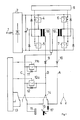
- the secondary sides of the current transformers 18, 19 connected as double flow transformers have two connections, each forming a feed line for a circuit A, B, and a common center connection C for the return of the currents.
- Within the circuits A, B are each have a rectifier diode 9, 10 in order to rectify the voltages induced in the secondary winding of the current transformers 18, 19.
- the circuits A, B or the center connection C can be connected to one 16 or the other connection 15 of the welding electrode in such a way that in a first position (DC) both circuits A, B via a choke 17 together with the Welding electrode connection 16 and the center connection C to the other connection 15 and in a second position (AC) the circuit A is connected to one connection 16 via the inductor 17 and the circuit B to the other connection 15 and the center connection C from the other connection 15 is separated.
- the smoothing inductor 17 serves to smooth the current profile fed into the welding electrode.
- connection of the center connection C to a respective supply line of the circuits A, B is in each case formed by a series connection of a diode 11, 12 or a controlled semiconductor switch 11a, 12a. Both semiconductor switches 11a, 12a are controlled jointly by a second control device 13.
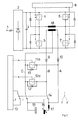
- the second exemplary embodiment of the invention shown in FIG. 2 differs from the first exemplary embodiment only in that the inverter in this case contains only a single current transformer 18. This is arranged as a push-pull converter in the middle branch of a bridge circuit, the bridge diagonal of which is alternately supplied with current by a common closing of the switches 5, 6 or 4.7.
- this current transformer is equivalent to that of the exemplary embodiment described above.
- the changeover switch 14 is in the solid position (DC) shown. Then the current flows through the alternately clocked circuits A, B in the same direction via the throttle 17 into the welding electrode connection 16 via the center connection C back to the current transformer.
- the semiconductor switches 11a, 12a are constantly open, so that the freewheeling diodes 11, 12 can each carry the current in the non-current-carrying phase of the converter.
- the changeover switch 14 is in the left, tipped position (AC). Assuming that circuit A is initially live, the current flows through smoothing inductor 17, welding electrode connection 16, other connection 15, changeover switch 14 and via semiconductor switch 12a, which is conductive during the current-carrying phase of circuit A, to center connection C of the current transformer. Since the other semiconductor switch 11a is open in this state, the diode 11 acts as a free-wheeling diode. In the other case, when the circuit B carries current, there is a current flow through the diode 9, the changeover switch 14, the other connection 15, the one connection 16, the smoothing inductor 17 and the then closed switch 11a back to the center connection C, here here the diode 12 acts as a freewheeling diode.
- the primary clock frequency of the current transformer 18 or 19 is set to a value of, for example, 25 kHz by the clock frequency of the first control device 8, the frequency of the AC voltage delivered to the welding electrode can be selected via the clock time of the second control device 13 can be set.
- the frequency of the AC voltage delivered to the welding electrode can be selected via the clock time of the second control device 13 can be set.
Landscapes
- Engineering & Computer Science (AREA)
- Physics & Mathematics (AREA)
- Plasma & Fusion (AREA)
- Mechanical Engineering (AREA)
- Arc Welding Control (AREA)
- Arc Welding In General (AREA)
Priority Applications (1)
| Application Number | Priority Date | Filing Date | Title |
|---|---|---|---|
| AT88120440T ATE89209T1 (de) | 1988-02-05 | 1988-12-07 | Lichtbogenschweissgeraet fuer gleich- und wechselstromspeisung. |
Applications Claiming Priority (2)
| Application Number | Priority Date | Filing Date | Title |
|---|---|---|---|
| DE3803447 | 1988-02-05 | ||
| DE3803447A DE3803447C1 (enExample) | 1988-02-05 | 1988-02-05 |
Publications (3)
| Publication Number | Publication Date |
|---|---|
| EP0326681A2 EP0326681A2 (de) | 1989-08-09 |
| EP0326681A3 EP0326681A3 (en) | 1990-01-03 |
| EP0326681B1 true EP0326681B1 (de) | 1993-05-12 |
Family
ID=6346696
Family Applications (1)
| Application Number | Title | Priority Date | Filing Date |
|---|---|---|---|
| EP88120440A Expired - Lifetime EP0326681B1 (de) | 1988-02-05 | 1988-12-07 | Lichtbogenschweissgerät für Gleich- und Wechselstromspeisung |
Country Status (3)
| Country | Link |
|---|---|
| EP (1) | EP0326681B1 (enExample) |
| AT (1) | ATE89209T1 (enExample) |
| DE (2) | DE3803447C1 (enExample) |
Families Citing this family (7)
| Publication number | Priority date | Publication date | Assignee | Title |
|---|---|---|---|---|
| DE4006202C2 (de) * | 1990-02-28 | 1996-08-01 | Rehm Gmbh U Co Schweistechnik | Verfahren zur Geräuschminderung |
| DE4023419C5 (de) * | 1990-07-23 | 2004-01-15 | Hitachi Seiko, Ltd., Ebina | Verfahren und Vorrichtung zum Steuern eines Wechselstrom-WIG-Schweißprozesses |
| DE4128175C2 (de) * | 1991-08-24 | 1994-05-19 | Elektro Werk Muendersbach Gmbh | Lichtbogenschweißgerät |
| DE4302443C1 (de) * | 1993-01-29 | 1994-05-26 | Elektro Werk Muendersbach Gmbh | Lichtbogenschweißgerät mit Halbleiterschaltern in Mittelpunktschaltung |
| DE19517875C2 (de) * | 1995-05-16 | 1997-05-07 | Michael Szczesny | Lichtbogenschweißgerät mit verbesserter Dynamik |
| DE19539038A1 (de) | 1995-10-20 | 1997-04-24 | Ewm High Tech Precision Schwei | Lichtbogenschweißgerät mit einem wechselstromgespeisten Gleichrichter |
| DE19738453C2 (de) * | 1997-09-03 | 2002-10-31 | Wolfgang Schuster | Inverterstromquelle |
Family Cites Families (4)
| Publication number | Priority date | Publication date | Assignee | Title |
|---|---|---|---|---|
| IT992372B (it) * | 1973-05-03 | 1975-09-10 | Maule C | Saldatrice elettrica ad arco a corrente continua costituita da convertitore di frequenza accop piato a convertitore di tensione e raddrizzatore |
| CS193265B1 (en) * | 1977-08-02 | 1979-10-31 | Josef Cibulka | Connection of the static welding source |
| DE2913625A1 (de) * | 1979-04-05 | 1980-10-16 | Messer Griesheim Gmbh | Einrichtung zum gleich- und/oder wechselstrom-lichtbogenschweissen mit einem an ein wechselstrom- oder gleichstromnetz anschliessbaren wechselrichter |
| SE438109B (sv) * | 1983-11-28 | 1985-04-01 | Esab Ab | Stromkella for ljusbagsvetsning |
-
1988
- 1988-02-05 DE DE3803447A patent/DE3803447C1/de not_active Expired
- 1988-12-07 AT AT88120440T patent/ATE89209T1/de not_active IP Right Cessation
- 1988-12-07 DE DE8888120440T patent/DE3881019D1/de not_active Expired - Fee Related
- 1988-12-07 EP EP88120440A patent/EP0326681B1/de not_active Expired - Lifetime
Non-Patent Citations (2)
| Title |
|---|
| PATENT ABSTRACTS OF JAPAN, Band 4, Nr. 96 (M-20)[578], 11. Juli 1980, Seite 59 M 20; & JP-A-55 54 274 (MATSUSHITA DENKI SANGYO K.K.) 21-04-1980 * |
| PATENT ABSTRACTS OF JAPAN, Band 7, Nr. 85 (M-206)[1230], 9. April 1983; & JP-A-58 9768 (SANSHIYA DENKI SEISAKUSHO K.K.) 20-01-1983 * |
Also Published As
| Publication number | Publication date |
|---|---|
| DE3803447C1 (enExample) | 1989-05-24 |
| ATE89209T1 (de) | 1993-05-15 |
| DE3881019D1 (de) | 1993-06-17 |
| EP0326681A2 (de) | 1989-08-09 |
| EP0326681A3 (en) | 1990-01-03 |
Similar Documents
| Publication | Publication Date | Title |
|---|---|---|
| DE3687999T2 (de) | Reihenschwingkreis-umrichter. | |
| EP0382110B1 (de) | Ausgangssteuerkreis für Inverter sowie Hochfrequenz-Stromquelle zur Gleichstromversorgung einer Schweissstation | |
| DE3034693C2 (de) | Impulsbreitengeregelter Gegentakt-Gleichspannungswandler | |
| EP1497910B1 (de) | Schaltnetzteilanordnung | |
| EP0283842B1 (de) | Umrichterschaltung mit einem Eintakt-Sperrumrichter | |
| EP0396126A2 (de) | Vorrichtung zur Stromversorgung | |
| EP0384222A1 (de) | Einspeiseschaltung für eine Mehrsystemlokomotive | |
| DE1962358A1 (de) | Lichtbogen-Schweissgeraet | |
| DE4112907C1 (en) | Mains-connected power supply circuit - has voltage doubler formed in two symmetrical circuit halves, and input voltage changeover switch for 115 or 230 volt operation | |
| EP0301274A2 (de) | Einrichtung für eine unipolar betriebene elektrische Schaltungskomponente | |
| EP0326681B1 (de) | Lichtbogenschweissgerät für Gleich- und Wechselstromspeisung | |
| DE10238606B4 (de) | Schaltnetzteil | |
| DE3419420A1 (de) | Unterbrechungsfreie stromversorgung | |
| DE2554826A1 (de) | Uebertrageranordnung fuer eine stromwandlerschaltung | |
| DE3105636A1 (de) | "einstellbare gleichspannungsversorgung" | |
| DE4302443C1 (de) | Lichtbogenschweißgerät mit Halbleiterschaltern in Mittelpunktschaltung | |
| DE4008652A1 (de) | Netzteil mit gleichstrom-gleichstrom-wandler | |
| DE729768C (de) | Einrichtung zur Entnahme von Schweissstrom aus einem Mehrphasennetz, die fuer die Lieferung von Gleich- oder Wechselstrom umschaltbar ist | |
| DE3535020A1 (de) | Wechselstrom-gleichstromwandler | |
| EP1081841B1 (de) | Schaltungsanordnung für einen Gleichrichter | |
| DE2714152C2 (de) | Schaltungsanordnung zur Erzeugung von Spannungen mit wechselnder Polarität aus einer Gleichspannung | |
| DE2853619A1 (de) | Gleichrichteranordnung | |
| EP1103330B1 (de) | Schweiss- oder Plasmaschneidgerät und Verfahren zum Betreiben eines Schweiss- oder Plasmaschneidgerätes | |
| DE3808433C1 (en) | Adjustable push-pull DC/DC converter and method for its control | |
| EP0263936A1 (de) | Sekundärseitig schaltbares Netzgerät |
Legal Events
| Date | Code | Title | Description |
|---|---|---|---|
| PUAI | Public reference made under article 153(3) epc to a published international application that has entered the european phase |
Free format text: ORIGINAL CODE: 0009012 |
|
| AK | Designated contracting states |
Kind code of ref document: A2 Designated state(s): AT BE CH DE ES FR GB GR IT LI LU NL SE |
|
| PUAL | Search report despatched |
Free format text: ORIGINAL CODE: 0009013 |
|
| AK | Designated contracting states |
Kind code of ref document: A3 Designated state(s): AT BE CH DE ES FR GB GR IT LI LU NL SE |
|
| 17P | Request for examination filed |
Effective date: 19900113 |
|
| RAP1 | Party data changed (applicant data changed or rights of an application transferred) |
Owner name: EWM ELEKTROWERK MUENDERSBACH VERWALTUNGSGESELLSCHA |
|
| 17Q | First examination report despatched |
Effective date: 19921027 |
|
| GRAA | (expected) grant |
Free format text: ORIGINAL CODE: 0009210 |
|
| AK | Designated contracting states |
Kind code of ref document: B1 Designated state(s): AT BE CH DE ES FR GB GR IT LI LU NL SE |
|
| PG25 | Lapsed in a contracting state [announced via postgrant information from national office to epo] |
Ref country code: SE Effective date: 19930512 Ref country code: NL Effective date: 19930512 Ref country code: GR Free format text: LAPSE BECAUSE OF FAILURE TO SUBMIT A TRANSLATION OF THE DESCRIPTION OR TO PAY THE FEE WITHIN THE PRESCRIBED TIME-LIMIT Effective date: 19930512 Ref country code: GB Effective date: 19930512 Ref country code: ES Free format text: THE PATENT HAS BEEN ANNULLED BY A DECISION OF A NATIONAL AUTHORITY Effective date: 19930512 Ref country code: BE Effective date: 19930512 |
|
| REF | Corresponds to: |
Ref document number: 89209 Country of ref document: AT Date of ref document: 19930515 Kind code of ref document: T |
|
| ET | Fr: translation filed | ||
| REF | Corresponds to: |
Ref document number: 3881019 Country of ref document: DE Date of ref document: 19930617 |
|
| ITF | It: translation for a ep patent filed | ||
| NLV1 | Nl: lapsed or annulled due to failure to fulfill the requirements of art. 29p and 29m of the patents act | ||
| GBV | Gb: ep patent (uk) treated as always having been void in accordance with gb section 77(7)/1977 [no translation filed] |
Effective date: 19930512 |
|
| PG25 | Lapsed in a contracting state [announced via postgrant information from national office to epo] |
Ref country code: AT Effective date: 19931207 |
|
| PG25 | Lapsed in a contracting state [announced via postgrant information from national office to epo] |
Ref country code: LU Free format text: LAPSE BECAUSE OF NON-PAYMENT OF DUE FEES Effective date: 19931231 Ref country code: LI Effective date: 19931231 Ref country code: CH Effective date: 19931231 |
|
| REG | Reference to a national code |
Ref country code: CH Ref legal event code: PL |
|
| PGFP | Annual fee paid to national office [announced via postgrant information from national office to epo] |
Ref country code: FR Payment date: 19991104 Year of fee payment: 12 |
|
| PGFP | Annual fee paid to national office [announced via postgrant information from national office to epo] |
Ref country code: DE Payment date: 20010123 Year of fee payment: 13 |
|
| PG25 | Lapsed in a contracting state [announced via postgrant information from national office to epo] |
Ref country code: FR Free format text: LAPSE BECAUSE OF NON-PAYMENT OF DUE FEES Effective date: 20010831 |
|
| REG | Reference to a national code |
Ref country code: FR Ref legal event code: ST |
|
| PG25 | Lapsed in a contracting state [announced via postgrant information from national office to epo] |
Ref country code: DE Free format text: LAPSE BECAUSE OF NON-PAYMENT OF DUE FEES Effective date: 20020702 |
|
| PG25 | Lapsed in a contracting state [announced via postgrant information from national office to epo] |
Ref country code: IT Free format text: LAPSE BECAUSE OF NON-PAYMENT OF DUE FEES;WARNING: LAPSES OF ITALIAN PATENTS WITH EFFECTIVE DATE BEFORE 2007 MAY HAVE OCCURRED AT ANY TIME BEFORE 2007. THE CORRECT EFFECTIVE DATE MAY BE DIFFERENT FROM THE ONE RECORDED. Effective date: 20051207 |
|
| PLBE | No opposition filed within time limit |
Free format text: ORIGINAL CODE: 0009261 |
|
| STAA | Information on the status of an ep patent application or granted ep patent |
Free format text: STATUS: NO OPPOSITION FILED WITHIN TIME LIMIT |