EP0326681B1 - Arc welding apparatus for direct and alternating current supply - Google Patents
Arc welding apparatus for direct and alternating current supply Download PDFInfo
- Publication number
- EP0326681B1 EP0326681B1 EP88120440A EP88120440A EP0326681B1 EP 0326681 B1 EP0326681 B1 EP 0326681B1 EP 88120440 A EP88120440 A EP 88120440A EP 88120440 A EP88120440 A EP 88120440A EP 0326681 B1 EP0326681 B1 EP 0326681B1
- Authority
- EP
- European Patent Office
- Prior art keywords
- connection
- current
- circuit
- welding electrode
- circuits
- Prior art date
- Legal status (The legal status is an assumption and is not a legal conclusion. Google has not performed a legal analysis and makes no representation as to the accuracy of the status listed.)
- Expired - Lifetime
Links
Images
Classifications
-
- B—PERFORMING OPERATIONS; TRANSPORTING
- B23—MACHINE TOOLS; METAL-WORKING NOT OTHERWISE PROVIDED FOR
- B23K—SOLDERING OR UNSOLDERING; WELDING; CLADDING OR PLATING BY SOLDERING OR WELDING; CUTTING BY APPLYING HEAT LOCALLY, e.g. FLAME CUTTING; WORKING BY LASER BEAM
- B23K9/00—Arc welding or cutting
- B23K9/10—Other electric circuits therefor; Protective circuits; Remote controls
- B23K9/1006—Power supply
- B23K9/1043—Power supply characterised by the electric circuit
- B23K9/1056—Power supply characterised by the electric circuit by using digital means
Landscapes
- Engineering & Computer Science (AREA)
- Physics & Mathematics (AREA)
- Plasma & Fusion (AREA)
- Mechanical Engineering (AREA)
- Arc Welding Control (AREA)
- Arc Welding In General (AREA)
Abstract
Description
Die Erfindung betrifft ein Lichtbogenschweißgerät bestehend aus einem wechselstromgespeisten Gleichrichter, der einen Zwischenkreis versorgt, mindestens einem an den Zwischenkreis angeschlossenen, von einer ersten Steuereinrichtung primärseitig wechselweise getakteten Stromwandler, der sekundärseitig Stromkreise mit einem gemeinsamen Mittenanschluß zur Speisung der Schweißelektrode bildet, welche jeweils parallel zur Schweißelektrode eine Freilaufdiode und in Reihe zur Schweißelektrode eine Gleichrichterdiode und eine Drossel enthalten.The invention relates to an arc welding device consisting of an AC-fed rectifier that supplies an intermediate circuit, at least one current transformer connected to the intermediate circuit and alternately clocked on the primary side by a first control device, which forms circuits on the secondary side with a common center connection for supplying the welding electrode, each of which is parallel to the welding electrode contain a free-wheeling diode and a rectifier diode and a choke in series with the welding electrode.
Ein solches Schweißgerät ist aus dem stand der Technik bekannt (US 4,564,742). Die Schweißelektrode wird bei dem bekannten Gerät derart angeschlossen, daß der Schweißstrom die Schweißelektrode nur in einer Richtung, also nur für Gleichstrombetrieb, durchfließen kann. Bei besonderen Anwendungsfällen, z.B. beim Schweißen von Aluminium, ist es jedoch erforderlich, daß die Schweißelektrode derart mit Strom versorgt wird, daß die während einer Schweißperiode mit einer, z.B. positiven Stromrichtung gebildete Oxidschicht durch einen gegengerichteten, negativen Strom während der folgenden Periode wieder aufgebrochen wird. Für einen solchen Wechselstrombetrieb ist das bekannte Scheißgerät jedoch nicht geeignet.Such a welding device is known from the prior art (US 4,564,742). The welding electrode is connected in the known device in such a way that the welding current can flow through the welding electrode only in one direction, that is to say only for direct current operation. In special applications, for example when welding aluminum, it is necessary that the welding electrode is used in this way Power is supplied such that the oxide layer formed during a welding period with, for example, a positive current direction is broken up again by a counter-directed, negative current during the following period. However, the known shitting device is not suitable for such an AC operation.
Ein anderes Lichtbogenschweißgerät ist aus der DE-OS 29 13 625 bekannt, bei welchem zwei getrennte Stromwandler vorgesehen sind, die jeweils zwei Primärteilwicklungen aufweisen. Auch dieses Schweißgerät ist nur für Gleichstrombetrieb geeignet. Darüberhinaus ist ein Lichtbogenschweißgerät aus "Schweißtechnik, Berlin 34 (1984), Nr. 8, S. 43 bis 342" bekannt, welches jedoch ebenfalls nur für Gleichstrombetrieb ausgelegt ist.Another arc welding device is known from DE-OS 29 13 625, in which two separate current transformers are provided, each having two primary part windings. This welding machine is also only suitable for DC operation. In addition, an arc welding device from "Schweißtechnik, Berlin 34 (1984), No. 8, pp. 43 to 342" is known, but this is also only designed for direct current operation.
Aus JP 55-54274 (A) ist eine Schaltungsanordnung für ein Lichtbogenschweißgerät bekannt, welches sekundärseitig Umschalter enthält, durch die der Lastkreis vom Gleichstrom - auf Wechselstrombetrieb umgeschaltet werden kann. Bei dieser eckigen Haltung sind jedoch keine Freilaufdioden parallel zur Schweißelektrode vorgesehen.From JP 55-54274 (A) a circuit arrangement for an arc welding device is known which contains changeover switches on the secondary side, by means of which the load circuit can be switched from direct current to alternating current operation. With this angular position, however, no free-wheeling diodes are provided parallel to the welding electrode.
Daher liegt der Erfindung die Aufgabe zugrunde, bei einem Lichtbogenschweißgerät der eingangs genannten Art eine Versorgung der Schweißelektrode auch mit Wechselstrom zu ermöglichen.The invention is therefore based on the object of making it possible to supply the welding electrode with alternating current in an arc welding device of the type mentioned at the outset.
Diese Aufgabe wird erfindungsgemäß dadurch gelöst, daß ein Umschalter vorgesehen ist, in dessen erster Stellung beide Stromkreise gemeinsam mit dem einen Anschluß der Schweißelektrode und der Mittenanschluß mit dem anderen Anschluß der Schweißelektrode und in dessen zweiter Stellung der erste Stromkreis mit dem einen Anschluß, der zweite Stromkreis mit dem anderen Anschluß verbunden ist und der Mittenanschluß vom anderen Anschluß getrennt ist, und daß parallel zu den Freilaufdioden erste und zweite, durch eine zweite Steuereinrichtung steuerbare Halbleiterschalter vorgesehen sind derart, daß in der zweiten Stellung des Umschalters der erste Halbleiterschalter den Strom des ersten Stromkreises und der zweite Halbleiterschalter den Strom des zweiten Stromkreises führt.This object is achieved in that a changeover switch is provided, in the first position of which both circuits together with one connection of the welding electrode and the center connection with the other connection of the welding electrode and in the second position of the first circuit with one connection, the second Circuit is connected to the other terminal and the center terminal is separated from the other terminal, and that Parallel to the freewheeling diodes, first and second semiconductor switches controllable by a second control device are provided such that in the second position of the switch, the first semiconductor switch carries the current of the first circuit and the second semiconductor switch carries the current of the second circuit.
Durch die Festlegung des jeweiligen Betriebszustandes des Schweißgerätes durch die Anschlußbelegung des Umschalters und die gesteuerten Halbleiterschalter, ergibt sich ein einfacher Aufbau des Schweißgerätes, da gegenüber dem Gleichstrombetrieb kein zusätzlicher schaltungstechnischer Aufwand erforderlich ist.By determining the respective operating state of the welding device through the pin assignment of the changeover switch and the controlled semiconductor switches, the welding device is of simple construction, since no additional circuitry complexity is required compared to direct current operation.
Während bei Gleichstromspeisung beide Stromkreise an einem gemeinsamen Anschluß der Schweißelektrode angeschlossen sind, durchfließen in der zweiten Stellung des Umschalters die den beiden Stromkreisen entstammenden Ströme die Schweißelektrode gegensinnig. Um in diesem, dem Wechselstrombetrieb entsprechenden Fall, geschlossene Stromkreise zu erhalten, werden parallel zu den Freilaufdioden Halbleiterschalter angeordnet, die jeweils während der Zeitintervalle durch die zweite Steuereinrichtung geschlossen werden, während der die zugehörigen Stromkreise stromführend sein sollen. Durch die Taktfrequenz der Halbleiterschalter kann somit die Wechselstromfrequenz des Schweißgerätes festgelegt werden.While with DC power supply both circuits are connected to a common connection of the welding electrode, in the second position of the switch the currents from the two circuits flow through the welding electrode in opposite directions. In order to obtain closed circuits in this case, which corresponds to AC operation, semiconductor switches are arranged parallel to the freewheeling diodes, which are closed by the second control device during the time intervals during which the associated circuits are to be live. The alternating current frequency of the welding device can thus be determined by the clock frequency of the semiconductor switches.
Darüber hinaus ergibt sich im Wechselstrombetrieb ein scharfer Übergang von der positiven zur negativen Stromphase, so daß insbesondere beim Schweißen von Aluminium ein sicherer Abbau der Oxidschicht erfolgen kann.In addition, in AC operation there is a sharp transition from the positive to the negative current phase, so that a reliable degradation of the oxide layer can take place, in particular when welding aluminum.
Ein besonderer Vorteil des erfindungsgemäßen Schweißgerätes ist darin zu sehen, daß, wenn die Taktfrequenz des Primärstromwandlers im Mittelfrequenzbereich, z.B. bei 25 kHz, liegt und die Frequenz der zweiten Steuerinrichtung variabel ist und z.B. zwischen 50 und 500 Hz liegt, sich die erforderliche Schweißfrequenz optimal dem Werkstückverhalten anpassen läßt.A particular advantage of the welding device according to the invention can be seen in the fact that when the clock frequency of the primary current transformer is in the medium frequency range, for example at 25 kHz, and the frequency of the second control device is variable and, for example, between 50 and 500 Hz, the required welding frequency can be optimally adapted to the workpiece behavior.
Die Erfindung wird im folgenden anhand einer zwei Ausführungsbeispiele schematisch dargestellten Zeichnung erläutert.The invention is explained below with reference to a drawing schematically shown two exemplary embodiments.
Dabei zeigen:
- Fig. 1
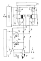
- ein Lichtbogenschweißgerät mit einen aus zwei Teilwandlern bestehenden Stromwandler
und - Fig. 2
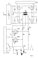
- ein Lichtbogenschweißgerät mit einem einteiligen Stromwandler
- Fig. 1
- an arc welding device with a current transformer consisting of two partial transformers
and - Fig. 2
- an arc welder with a one-piece current transformer
Die Sekundärseiten der als Doppeldurchflußwandler geschalteten Stromwandler 18,19 weisen zwei, jeweils eine Zuleitung für einen Stromkreis A,B bildende Anschlüsse und einen gemeinsamen Mittenanschluß C für die Rückleitung der Ströme auf. Innerhalb der Stromkreise A,B befinden sich jeweils eine Gleichrichterdiode 9,10, um die jeweils in der Sekundärwicklung der Stromwandler 18,19 induzierten Spannungen gleichzurichten.The secondary sides of the
Über einen Umschalter 14 können die Stromkreise A,B bzw. der Mittenanschluß C derart mit dem einen 16 oder dem andere Anschluß 15 der Schweißelektrode verbunden werden, daß in einer ersten Stellung (DC) beide Stromkreise A, B über eine Drossel 17 gemeinsam mit dem Schweißelektrodenanschluß 16 sowie der Mittenanschluß C mit dem anderen Anschluß 15 und in einer zweiten Stellung (AC) der Stromkreis A über die Drossel 17 mit dem einen Anschluß 16 sowie der Stromkreis B mit dem anderen Anschluß 15 verbunden sind und der Mittenanschluß C vom anderen Anschluß 15 getrennt ist. Die Glättungsdrossel 17 dient zur Glättung des in die Schweißelektrode eingespeisten Stromverlaufes.Via a
Die Verbindung des Mittenanchlusses C zu jeweils einer Zuleitung der Stromkreise A,B wird jeweils durch eine Reihenschaltung aus einer Diode 11,12 bzw. einem gesteuerten Halbleiterschalter 11a,12a gebildet. Beide Halbleiterschalter 11a,12a werden gemeinsam von einer zweiten Steuereinrichtung 13 angesteuert.The connection of the center connection C to a respective supply line of the circuits A, B is in each case formed by a series connection of a
Das in Fig. 2 dargestellte zweite Ausführungsbeispiel der Erfindung unterscheidet sich vom ersten Ausführungsbeispiel nur dadurch, daß der Wechselrichter in diesem Falle nur einen einzigen Stromwandler 18 enthält. Dieser ist als Gegentaktwandler im Mittenzweig einer Brückenschaltung angeordnet, deren Brückendiagonale jeweils durch ein gemeinsames Schließen der Schalter 5,6 bzw. 4,7 wechselweise mit Strom versorgt wird.The second exemplary embodiment of the invention shown in FIG. 2 differs from the first exemplary embodiment only in that the inverter in this case contains only a single
Hinsichtlich seiner Funktion ist dieser Stromwandler jedoch äquivalent zu dem des zuvor geschilderten Ausführungsbeispieles. Aus diesem Grunde kann die Darstellung der Funktionsweise des erfindungsgemäßen Schweißgeätes für beide Ausführungsbeispiele gemeinsam erfolgen:
Im Falle der Speisung der Schweißelektrode 16,15 mit Gleichstrom ist der Umschalter 14 in der dargestellten, durchgezogenen Stellung (DC). Dann fließt der Strom durch die wechselweise getakteten Stromkreise A,B gleichsinnig über die Drossel 17 in den Schweißelektrodenanschluß 16 über den Mittenanschluß C zurück zum Stromwandler. In diesem Betriebszustand sind die Halbleiterschalter 11a,12a ständig geöffnet, so daß die Freilaufdioden 11,12 jeweils den Strom in der nicht stromführenden Phase des Wandlers führen können.With regard to its function, however, this current transformer is equivalent to that of the exemplary embodiment described above. For this reason, the The functioning of the welding device according to the invention is shown jointly for both exemplary embodiments:
If the
Im Wechselstrombetrieb befindet sich der Umschalter 14 in der linken, gestichelten Stellung (AC). Unter Annahme, daß zunächst der Stromkreis A stromführend ist, fließt der Strom über die Glättungsdrossel 17, den Schweißelektrodenanschluß 16, den anderen Anschluß 15, den Umschalter 14 und über den während der stromführenden Phase des Stromkreises A leitenden Halbleiterschalter 12a zum Mittenanschluß C des Stromwandlers. Da der andere Halbleiterschalter 11a in diesem Zustand geöffnet ist, wirkt die Diode 11 als Freilaufdiode. Im anderen Fall, wenn der Stromkreis B Strom führt, ergibt sich ein Stromfluß über die Diode 9, den Umschalter 14, den anderen Anschluß 15, den einen Anschluß 16, die Glättungsdrossel 17 und den dann geschlossenen Schalter 11a zurück zum Mittenanschluß C, wobei hier die Diode 12 als Freilaufdiode wirkt.In AC operation, the
Während die primäre Taktfrequenz des Stromwandlers 18 bzw. 19 durch die Taktfrequenz der ersten Steuereinrichtung 8 auf einen Wert von z.B. 25 kHz eingestellt wird, kann die an die Schweißelektrode abgegebene Frequenz der Wechselspannung über die Taktzeit der zweiten Steuereinrichtung 13 wählbar eingestellt werden. Hierdurch ist ein weitgehende Anpassung an die Erfordernisse im jeweiligen Anwendungsfall möglich; insbesondere ist es beim Aluminiumschweißen sinnvoll, eine Wechselfrequenz zwischen 50 und 500 Hz zu wählen.While the primary clock frequency of the
Claims (3)
- An arc welding apparatus comprising a rectifier (2) which is supplied with alternating current and which supplies an intermediate circuit (3); and at least one current transducer (18, 19) which is connected to the intermediate circuit (3) and which is alternately timed on the primary side by a control device (8) and which on the secondary side forms circuits (A, B) with a common central connection (C) to supply the welding electrode (15, 16), the circuits (A, B) each comprising a freewheeling diode in parallel with the welding electrode (15, 16) and a rectifier diode (9, 10) and a choke (17) in series with the welding electrode (9, 10), characterized in that a reversing switch (14) is provided in whose first position (DC) both circuits (A, B) are jointly connected to one connection (16) of the welding electrode and the central connection (C) to the other connection (15) of the welding electrode, and in whose second position (AC) the first circuit (A) is connected to one connection (16) and the second circuit (B) to the other connection (15), the central connection (C) being separated from the other connection (15), and first (11a) and second (12a) semiconductor switches controllable via a second control device (13) are so provided in parallel with the freewheeling diodes (11, 12) that in the second position of the reversing switch (14) the first semiconductor switch (12a) carries the current of the first circuit (A) and the second semiconductor switch (11a) carries the current of the second circuit (B).
- An arc welding apparatus according to claim 1, characterized in that the timing-pulse rate of the first control device (8) lies in the medium frequency range, being more particularly 25 kHz, and the timing-pulse rate of the second control device (13) can be varied, more particularly between 50 and 500 Hz.
- An arc welding apparatus according to claims 1 or 2, characterized in that each freewheeling diode (11, 12) is combined with each semiconductor switch (11a, 12a) to form a common component.
Priority Applications (1)
| Application Number | Priority Date | Filing Date | Title |
|---|---|---|---|
| AT88120440T ATE89209T1 (en) | 1988-02-05 | 1988-12-07 | ARC WELDING MACHINE FOR DIRECT AND AC POWER SUPPLY. |
Applications Claiming Priority (2)
| Application Number | Priority Date | Filing Date | Title |
|---|---|---|---|
| DE3803447A DE3803447C1 (en) | 1988-02-05 | 1988-02-05 | |
| DE3803447 | 1988-02-05 |
Publications (3)
| Publication Number | Publication Date |
|---|---|
| EP0326681A2 EP0326681A2 (en) | 1989-08-09 |
| EP0326681A3 EP0326681A3 (en) | 1990-01-03 |
| EP0326681B1 true EP0326681B1 (en) | 1993-05-12 |
Family
ID=6346696
Family Applications (1)
| Application Number | Title | Priority Date | Filing Date |
|---|---|---|---|
| EP88120440A Expired - Lifetime EP0326681B1 (en) | 1988-02-05 | 1988-12-07 | Arc welding apparatus for direct and alternating current supply |
Country Status (3)
| Country | Link |
|---|---|
| EP (1) | EP0326681B1 (en) |
| AT (1) | ATE89209T1 (en) |
| DE (2) | DE3803447C1 (en) |
Families Citing this family (7)
| Publication number | Priority date | Publication date | Assignee | Title |
|---|---|---|---|---|
| DE4006202C2 (en) * | 1990-02-28 | 1996-08-01 | Rehm Gmbh U Co Schweistechnik | Noise reduction process |
| DE4023419C5 (en) * | 1990-07-23 | 2004-01-15 | Hitachi Seiko, Ltd., Ebina | Method and device for controlling an AC TIG welding process |
| DE4128175C2 (en) * | 1991-08-24 | 1994-05-19 | Elektro Werk Muendersbach Gmbh | Arc welder |
| DE4302443C1 (en) * | 1993-01-29 | 1994-05-26 | Elektro Werk Muendersbach Gmbh | Arc welding equipment with semiconductor-switched sec. current paths - is based on switched-prim. transformer with two sec. windings in same direction switched by separate semiconductors in push=pull mode |
| DE19517875C2 (en) * | 1995-05-16 | 1997-05-07 | Michael Szczesny | Arc welding machine with improved dynamics |
| DE19539038A1 (en) | 1995-10-20 | 1997-04-24 | Ewm High Tech Precision Schwei | Arc welder with an AC powered rectifier |
| DE19738453C2 (en) * | 1997-09-03 | 2002-10-31 | Wolfgang Schuster | Inverter power source |
Family Cites Families (7)
| Publication number | Priority date | Publication date | Assignee | Title |
|---|---|---|---|---|
| IT992372B (en) * | 1973-05-03 | 1975-09-10 | Maule C | DIRECT CURRENT ELECTRIC ARC WELDING MACHINE CONSISTS OF A FREQUENCY CONVERTER COUPLED TO A VOLTAGE CONVERTER AND RECTIFIER |
| CS193265B1 (en) * | 1977-08-02 | 1979-10-31 | Josef Cibulka | Connection of the static welding source |
| JPS5554274A (en) * | 1978-10-13 | 1980-04-21 | Matsushita Electric Ind Co Ltd | Arc welding machine |
| DE2913625A1 (en) * | 1979-04-05 | 1980-10-16 | Messer Griesheim Gmbh | DEVICE FOR DC AND / OR AC ARC WELDING WITH A INVERTER TO BE CONNECTED TO AN AC OR DC NETWORK |
| JPS589768A (en) * | 1981-07-07 | 1983-01-20 | Sansha Electric Mfg Co Ltd | Electric power source device for arc welding machine |
| JPS58205678A (en) * | 1982-05-26 | 1983-11-30 | Matsushita Electric Ind Co Ltd | Arc welding machine |
| SE438109B (en) * | 1983-11-28 | 1985-04-01 | Esab Ab | STROMKELLA FOR LIGHT REAR WELDING |
-
1988
- 1988-02-05 DE DE3803447A patent/DE3803447C1/de not_active Expired
- 1988-12-07 AT AT88120440T patent/ATE89209T1/en not_active IP Right Cessation
- 1988-12-07 EP EP88120440A patent/EP0326681B1/en not_active Expired - Lifetime
- 1988-12-07 DE DE8888120440T patent/DE3881019D1/en not_active Expired - Fee Related
Non-Patent Citations (2)
| Title |
|---|
| PATENT ABSTRACTS OF JAPAN, Band 4, Nr. 96 (M-20)[578], 11. Juli 1980, Seite 59 M 20; & JP-A-55 54 274 (MATSUSHITA DENKI SANGYO K.K.) 21-04-1980 * |
| PATENT ABSTRACTS OF JAPAN, Band 7, Nr. 85 (M-206)[1230], 9. April 1983; & JP-A-58 9768 (SANSHIYA DENKI SEISAKUSHO K.K.) 20-01-1983 * |
Also Published As
| Publication number | Publication date |
|---|---|
| DE3803447C1 (en) | 1989-05-24 |
| EP0326681A2 (en) | 1989-08-09 |
| DE3881019D1 (en) | 1993-06-17 |
| EP0326681A3 (en) | 1990-01-03 |
| ATE89209T1 (en) | 1993-05-15 |
Similar Documents
| Publication | Publication Date | Title |
|---|---|---|
| EP0382110B1 (en) | Output control circuit for reversers, and high-frequency power supply for the DC supply of a welding station | |
| DE3034693C2 (en) | Pulse-width controlled push-pull DC voltage converter | |
| EP1497910B1 (en) | Switched-mode power supply arrangement | |
| EP0283842B1 (en) | Flyback switching converter | |
| EP0384222A1 (en) | Supply circuit for a multisystem locomotive | |
| EP0396126A2 (en) | Power supply device | |
| DE1962358A1 (en) | Arc welding machine | |
| EP0301274A2 (en) | Device for a one-pole-controlled electric circuit component | |
| DE4112907C1 (en) | Mains-connected power supply circuit - has voltage doubler formed in two symmetrical circuit halves, and input voltage changeover switch for 115 or 230 volt operation | |
| EP0326681B1 (en) | Arc welding apparatus for direct and alternating current supply | |
| DE10238606B4 (en) | Switching Power Supply | |
| DE3419420A1 (en) | UNINTERRUPTIBLE POWER SUPPLY | |
| DE2554826A1 (en) | TRANSFER ARRANGEMENT FOR A CURRENT CONVERTER CIRCUIT | |
| DE3105636A1 (en) | "ADJUSTABLE DC VOLTAGE SUPPLY" | |
| DE4302443C1 (en) | Arc welding equipment with semiconductor-switched sec. current paths - is based on switched-prim. transformer with two sec. windings in same direction switched by separate semiconductors in push=pull mode | |
| DE4008652A1 (en) | Mains unit with DC-to-DC converter - has primary transformer stage with transistor switch operated in pulsed mode controlled by feedback | |
| DE729768C (en) | Device for drawing welding current from a multi-phase network, which can be switched for the supply of direct or alternating current | |
| EP0743126A2 (en) | Arc welding device with improved dynamic characteristics | |
| EP0410088A2 (en) | Welding or plasma cutting device with stabilized voltage of indirect circuit | |
| DE2714152C2 (en) | Circuit arrangement for generating voltages with alternating polarity from a direct voltage | |
| DE2853619A1 (en) | RECTIFIER ARRANGEMENT | |
| EP1081841B1 (en) | Circuit arrangement for a rectifier | |
| EP1103330B1 (en) | Welding or plasma cutting device and method for operation a welding or plasma cutting device | |
| DE3808433C1 (en) | Adjustable push-pull DC/DC converter and method for its control | |
| EP0263936A1 (en) | Secondary side switchable power supply device |
Legal Events
| Date | Code | Title | Description |
|---|---|---|---|
| PUAI | Public reference made under article 153(3) epc to a published international application that has entered the european phase |
Free format text: ORIGINAL CODE: 0009012 |
|
| AK | Designated contracting states |
Kind code of ref document: A2 Designated state(s): AT BE CH DE ES FR GB GR IT LI LU NL SE |
|
| PUAL | Search report despatched |
Free format text: ORIGINAL CODE: 0009013 |
|
| AK | Designated contracting states |
Kind code of ref document: A3 Designated state(s): AT BE CH DE ES FR GB GR IT LI LU NL SE |
|
| 17P | Request for examination filed |
Effective date: 19900113 |
|
| RAP1 | Party data changed (applicant data changed or rights of an application transferred) |
Owner name: EWM ELEKTROWERK MUENDERSBACH VERWALTUNGSGESELLSCHA |
|
| 17Q | First examination report despatched |
Effective date: 19921027 |
|
| GRAA | (expected) grant |
Free format text: ORIGINAL CODE: 0009210 |
|
| AK | Designated contracting states |
Kind code of ref document: B1 Designated state(s): AT BE CH DE ES FR GB GR IT LI LU NL SE |
|
| PG25 | Lapsed in a contracting state [announced via postgrant information from national office to epo] |
Ref country code: SE Effective date: 19930512 Ref country code: NL Effective date: 19930512 Ref country code: GR Free format text: LAPSE BECAUSE OF FAILURE TO SUBMIT A TRANSLATION OF THE DESCRIPTION OR TO PAY THE FEE WITHIN THE PRESCRIBED TIME-LIMIT Effective date: 19930512 Ref country code: GB Effective date: 19930512 Ref country code: ES Free format text: THE PATENT HAS BEEN ANNULLED BY A DECISION OF A NATIONAL AUTHORITY Effective date: 19930512 Ref country code: BE Effective date: 19930512 |
|
| REF | Corresponds to: |
Ref document number: 89209 Country of ref document: AT Date of ref document: 19930515 Kind code of ref document: T |
|
| ET | Fr: translation filed | ||
| REF | Corresponds to: |
Ref document number: 3881019 Country of ref document: DE Date of ref document: 19930617 |
|
| ITF | It: translation for a ep patent filed |
Owner name: SOCIETA' ITALIANA BREVETTI S.P.A. |
|
| NLV1 | Nl: lapsed or annulled due to failure to fulfill the requirements of art. 29p and 29m of the patents act | ||
| GBV | Gb: ep patent (uk) treated as always having been void in accordance with gb section 77(7)/1977 [no translation filed] |
Effective date: 19930512 |
|
| PG25 | Lapsed in a contracting state [announced via postgrant information from national office to epo] |
Ref country code: AT Effective date: 19931207 |
|
| PG25 | Lapsed in a contracting state [announced via postgrant information from national office to epo] |
Ref country code: LU Free format text: LAPSE BECAUSE OF NON-PAYMENT OF DUE FEES Effective date: 19931231 Ref country code: LI Effective date: 19931231 Ref country code: CH Effective date: 19931231 |
|
| REG | Reference to a national code |
Ref country code: CH Ref legal event code: PL |
|
| PGFP | Annual fee paid to national office [announced via postgrant information from national office to epo] |
Ref country code: FR Payment date: 19991104 Year of fee payment: 12 |
|
| PGFP | Annual fee paid to national office [announced via postgrant information from national office to epo] |
Ref country code: DE Payment date: 20010123 Year of fee payment: 13 |
|
| PG25 | Lapsed in a contracting state [announced via postgrant information from national office to epo] |
Ref country code: FR Free format text: LAPSE BECAUSE OF NON-PAYMENT OF DUE FEES Effective date: 20010831 |
|
| REG | Reference to a national code |
Ref country code: FR Ref legal event code: ST |
|
| PG25 | Lapsed in a contracting state [announced via postgrant information from national office to epo] |
Ref country code: DE Free format text: LAPSE BECAUSE OF NON-PAYMENT OF DUE FEES Effective date: 20020702 |
|
| PG25 | Lapsed in a contracting state [announced via postgrant information from national office to epo] |
Ref country code: IT Free format text: LAPSE BECAUSE OF NON-PAYMENT OF DUE FEES;WARNING: LAPSES OF ITALIAN PATENTS WITH EFFECTIVE DATE BEFORE 2007 MAY HAVE OCCURRED AT ANY TIME BEFORE 2007. THE CORRECT EFFECTIVE DATE MAY BE DIFFERENT FROM THE ONE RECORDED. Effective date: 20051207 |
|
| PLBE | No opposition filed within time limit |
Free format text: ORIGINAL CODE: 0009261 |
|
| STAA | Information on the status of an ep patent application or granted ep patent |
Free format text: STATUS: NO OPPOSITION FILED WITHIN TIME LIMIT |