EP0326422A2 - Conteneur de volaille et système pour le désempilage, le déchargement et l'empilage du conteneur - Google Patents
Conteneur de volaille et système pour le désempilage, le déchargement et l'empilage du conteneur Download PDFInfo
- Publication number
- EP0326422A2 EP0326422A2 EP89300835A EP89300835A EP0326422A2 EP 0326422 A2 EP0326422 A2 EP 0326422A2 EP 89300835 A EP89300835 A EP 89300835A EP 89300835 A EP89300835 A EP 89300835A EP 0326422 A2 EP0326422 A2 EP 0326422A2
- Authority
- EP
- European Patent Office
- Prior art keywords
- container
- containers
- conveyor
- elevator
- poultry
- Prior art date
- Legal status (The legal status is an assumption and is not a legal conclusion. Google has not performed a legal analysis and makes no representation as to the accuracy of the status listed.)
- Withdrawn
Links
Images


Classifications
-
- A—HUMAN NECESSITIES
- A01—AGRICULTURE; FORESTRY; ANIMAL HUSBANDRY; HUNTING; TRAPPING; FISHING
- A01K—ANIMAL HUSBANDRY; CARE OF BIRDS, FISHES, INSECTS; FISHING; REARING OR BREEDING ANIMALS, NOT OTHERWISE PROVIDED FOR; NEW BREEDS OF ANIMALS
- A01K45/00—Other aviculture appliances, e.g. devices for determining whether a bird is about to lay
- A01K45/005—Harvesting or transport of poultry
-
- A—HUMAN NECESSITIES
- A01—AGRICULTURE; FORESTRY; ANIMAL HUSBANDRY; HUNTING; TRAPPING; FISHING
- A01K—ANIMAL HUSBANDRY; CARE OF BIRDS, FISHES, INSECTS; FISHING; REARING OR BREEDING ANIMALS, NOT OTHERWISE PROVIDED FOR; NEW BREEDS OF ANIMALS
- A01K31/00—Housing birds
- A01K31/002—Poultry cages, e.g. transport boxes
-
- A—HUMAN NECESSITIES
- A01—AGRICULTURE; FORESTRY; ANIMAL HUSBANDRY; HUNTING; TRAPPING; FISHING
- A01K—ANIMAL HUSBANDRY; CARE OF BIRDS, FISHES, INSECTS; FISHING; REARING OR BREEDING ANIMALS, NOT OTHERWISE PROVIDED FOR; NEW BREEDS OF ANIMALS
- A01K31/00—Housing birds
- A01K31/06—Cages, e.g. for singing birds
- A01K31/07—Transportable cages ; Travelling cages for pigeons; Opening or closing of cages
Definitions
- the present invention is a stackable poultry container, and a system for destacking the containers when they are loaded with poultry, and for cleaning and restacking the containers after they have been unloaded.
- Poultry (“birds") are typically manually caught and transported in cages and, at some point following the arrival of the cages at a processing plant, the birds must be removed from the cages and transferred to a processing line for further processing.
- cages are relatively shallow in height compared to their length and width, as they are designed to be about the height of a mature bird, but long enough and wide enough to hold a number of birds in a single layer.
- the birds are removed from the cages and placed on a processing line, again typically by hand labor.
- poultry cages or containers typically have side opening doors. These are most convenient for use when placing birds into the relatively shallow containers, but are generally awkward when birds are to be removed. Birds are most easily removed, and damaged the least, from open topped containers. Birds cannot be securely held or transported in an open-topped container, however, so some additional structure is generally required. Furthermore, where manual loading of birds is desired or necessary, an open-top container permits such hand loading with minimum damage to the birds and a good distribution of birds in each basket.
- the birds are placed in open-topped containers which during transport fit like drawers into a supporting structure.
- a supporting structure has no use other than support of the container and thereby adds extra weight and storage burdens to any given transport and offload system.
- an offloading system for poultry which is a combination of one or more stackable and destackable poultry containers which are suitable for being loaded with automated entrapment systems, as well as by manual labor.
- the combination includes a stackable and destackable container which has a generally rectangular floor and substantially vertical side walls and end walls to form a generally rectangular container with four corners.
- Projecting members extend vertically upwardly and apertures open downwardly from the bottom of each corner with the apertures conforming in dimensions to the projecting members for interengagement therewith.
- One of the vertical end walls is hingedly mounted to form a door which pivots upwardly and inwardly during the loading of chickens into the container.
- the combination also includes an apparatus for destacking loaded and stacked containers and for restacking the containers when they are empty.
- This apparatus comprises a conveyor for moving a stack of containers along a predetermined path of travel, an apparatus for successively removing one container at a time from a stack of containers, a conveyor for advancing unstacked containers along a line during which poultry can be removed from the open tops of the containers, and an apparatus for successively adding one empty container at a time to a stack of empty containers.
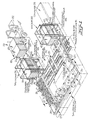
- Figure 1 illustrates an overall view of the unstacking, unloading, transfer and restacking features of the present invention, along with the disassemblable chicken carrying modules.
- These modules are broadly designated at 20 and in Figure 1 are shown as a stack of five of the individual stackable and destackable containers which in turn are broadly designated at 21 and will be described in more detail hereafter.
- two adjacent container modules 20 are unloaded froma forklift truck 22 which has transferred them from some other location, for example a truck.
- the container modules 20 travel along a conveyor 23 into the destacker 24.
- the particular construction and operation of the destacker 24 will by discussed in greater detail with references to Figures 3A-3H, and Figures 5, 6, 7, 8 and 10.
- the embodiment of the destacker 24 shown is capable of concurrently destacking a pair of modules 20 into individual containers 21 using container latching means 25 and an elevatable conveyor table.
- the destacked containers 21 continue traveling along conveyor 23 while the lid and base portions of the modules 27 and 30, respectively, are transferred to another conveyor broadly designated at 31 which carries them to be washed and then restacked into modules.
- the destacked conveyors 21 travel along conveyor 23, they are eventually directed to the stacker broadly designated at 33.
- the path of the conveyor 23 from the destacker 24 to the stacker 33 forms a generally U-shaped configuration, which offers several advantages in the practice of the invention, but which is not absolutely critical to the operation of the invention, it being understood that other conveyor configurations may be possible, desirable, or even necessary under some circumstances without departing from the spirit or teaching of the invention.
- the majority of the path of the conveyor 23 between the destacker 24 and the stacker 33 provides an area in which birds can be lifted out of the open containers and transferred to other conventional poultry carrying devices, a number of examples of which are commercially known and available. All of this portion of the path of the conveyor 23 therefore forms a bird removal area, portions of which are broadly designated at 34 in Figure 1. As illustrated therein, the containers 21 may be additionally guided along the conveyor 23 by a series of guides or railings 35 which run along the sides of the conveyor 23.
- a container wash broadly designated at 36 may optionally be included along the conveyor 23 following the bird removal area snd prior to the stacker 33.
- the containers 21, the lids 27, and the bases 30 are all brought together at the stacker 33 and reassembled into modules, a portion of one of which is illustrated at the stacker 33 in Figure 1.
- the operation of the stacker 33 will be discussed in more detail with reference to Figures 4A-4H and Figure 9.
- the stacker 33 includes container latching means 37 which are substantially the same in structure and operation to the container latching means 25 of the destacker 24, but which are present in only one set.
- Figure 1 also shows an overall view of the raising and lowering means 40 for a conveyor table 45 of the stacker which basically comprises a hydraulic cylinder 41 and piston 42 which drive a series of chains 43, which in conjunction with sprockets 44 raise and lower conveyor table 45 which is either similar or identical to, depending upon the chose embodiment, the elevatable conveyor table 26 of the destacker.
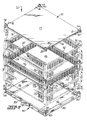
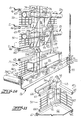
- Figure 2 is partially exploded perspective view of one container 21, a module lid 26, and a module base 30.
- the container 21 comprises a generally rectangular floor 46, a pair of substantially vertical side walls, generally designated at 47 and 50, and a pair of substantially vertical end walls generally designated at 51 and 52. All of the walls extend perpendicularly upwardly from the floor 46 with the end walls 51 and 52 connected to the side walls 47 and 50 to form a generally rectangular container with four corners.
- the container 21 of the present invention can be formed of aluminum, stainless steel or other appropriate metallic material, or in other embodiments can be formed of appropriate synthetic materials such as high impact polymeric materials, laminated composites or any other material which otherwise meets the structural and chemical demands associated with the handling of live poultry.
- the container 21 is formed of a framework of generally rectangular metal pieces with square cross-sections, several pieces of metal with channel-type cross-sections, and some wire portions which form the side and end walls and which provide ample ventilation for birds in the container 21.
- the four corners are defined by posts, three of which are visible in the view of Figure 2 and are designated at 53.
- a projecting member 54 extends vertically upwardly from the top of each corner in the shape of a truncated pyramid.
- Each corner post 53 likewise contains an aperture 55 which conforms in shape and dimension to the truncated pyramid projecting members 54.
- the projecting members 54 conform in dimension to the apertures 55 and are positioned at the corner post 53 of the container 21, any number of such containers can be stacked one upon another in matingly receivable engagement to form a portion of a resulting module 20.
- Figure 2 shows some additional details of the container 21, one of which is the vertical end wall 51 being hingedly mounted on hinges 56 to pivot upwardly and inwardly as a door during the loading of chickens therein.
- Figure 11 is a partially broken away perspective view of a corner of the container 21.
- Figure 11 shows the corner post 53, the projecting member 54, a portion of the floor 46, the interconnected horizontal and vertical wires 57 and 60, respectively, which form the side and end walls, framework members 61 and 62 beneath the floor 46, framework member 63 along the upper portion of the side wall 47, a channel-shaped framework member 64 along the upper portion of end wall 51 and upon which hinge 56 is partially mounted, and framework members 65 and 66 which form the inwardly and upwardly pivoting door portion of end wall 51.
- the hinge 56 comprises two pieces of angled metal 67 and 70 and a bolt 71 which passes between respective openings in the angled metal portions 67 and 70.
- the position of the hinge 56 combined with the extension of the framework member 66 which rests against the post 53 provides a door within side wall 51 which can swing upwardly and inwardly but which is blocked from swinging outwardly by the engagement of framework member 66 with post 53.
- the inwardly and upwardly swinging door of the present invention is particularly useful in combination with certain mechanized chicken harvesters such as are the subject of applicant's aforementioned U.S. Patent No. 4,766,850 for "Method and Apparatus for Collecting and Conveying Objects From a Surface".
- the end wall 51 also includes a solid portion 72 into which is formed a curved bumper portion 73.
- a curved bumper portion 73 When the bumper portion 73 is engaged by some external apparatus, such as the loading conveyors or other portions of a mechanized poultry harvester, the door will swing inwardly and upwardly with the bumpers 73 protecting the wire portions or framework of end wall 51 from damage.
- the container 21 of the present invention further includes panel portions 74 along the side wall 50, a corresponding pair of which are also present on side wall 47, but are not visible in the particular view of Figure 2.
- These panel portions each include a generally rectangularly shaped opening 75 which receives portions of the cage latching means 25 and 37 which have been noted in Figure 1 and which will be described in more detail hereinafter.
- the containers of the present invention are particularly useful with respect to automated or mechanical loading systems, the containers offer advantages for manual loading as well.
- the open-top containers of the invention facilitate hand loading with minimum damage to the birds and good distribution of birds within the container.
- an upper container when two or more containers are stacked, an upper container can be partially tilted or pivoted apart from a lower container along one of the walls in a manner analogous to the opening of a jaw or in a "clamshell” fashion to permit birds to be hand loaded into the lower of the two containers.
- the upper container can be maintained in its tilted position using a solid prop or jack, or any other suitable conventional item. In this manner, the containers can still be stacked, destacked, unloaded and restacked using the system of the present invention even when the containers are conventionally hand loaded.
- FIG. 2 also illustrates the lid portion 27 and the base portion 30, which along with one or more stacked containers 21 forms the disassemblable module 20.
- Lid 27 is formed of a generally rectangular framework of members 76 which are generally similar to the other framework members described herein with the possible exception of differences in dimension and cross-section for various structural purposes.
- a planar solid cover 77 is supported by the framework members 76 and forms the solid barrier portion of the lid of a module.
- the framework members are connected to one another at the corner posts 80 which include projecting members 54 identical to those described with respect to the container 21, and apertures 55 which are likewise identical to the apertures 55 described with respect to the container 21.
- the lid 27 will matingly engage with a container 21 and form the lid of the module 20, and because the lid 27 includes the projecting members 54, a container 21 can be matingly engaged upon the lid 27 as well as beneath it.
- modules 20 can be stacked upon one another, as the base of each module is matingly engaged with the lid of a module below it or above it, respectively.
- the lid 27 further includes L-shaped members 81 which form openings adjacent opposite framework members 76 for receiving the cage latching means 25 and 37 in the same manner in which they are received by the openings 75 in the container 21 and as will be more fully described with respect ot Figures 7, 8, 9 and 10.
- Base 30 also comprises a generally rectangular framework which is defined by framework members 82 along the portions corresponding to end walls 50 and 47 of the container, and spaced parallel framework members 83 and 84 which form the other respective sides of the generally rectangular base 30.
- Framework members 82, 83 and 84 meet at respective corner posts 85 which in turn include projecting members 54 and apertures 55 identical to those of the container 21 and the lid 27.
- Figure 2 demonstrates that with these respective identical projecting members 54 and apertures 55 present on the base 30, the container 21, and the lid 27, these elements can be assembled in any order or fashion whatsoever to form disassemblable modules customized for particular uses.
- Figure 3 also illustrates that the base 30 includes box girders 86 which form entries for external lifting means such as the forks of a forklift truck so that the entire module can be transported in convenient fashion ( Figure 1).
- the framework members 83 and 84 are also supported by smaller, upright framework members 87.
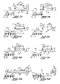
- FIGS 3A-3H schematically demonstrate the operation of the destacker 24.
- two modules 20 individual containers 21, portions of the conveyor 23, the elevatable conveyor table 26, the lid 27 and base 30 portions of each module, and the base and lid transfer conveyor 31.
- the conveyor 31 includes a plurality of driven belts 90 which travel between respective belt pulleys 91 and carry the bases and lids from a position adjacent the destacker 24 to a position adjacent the stacker 33 all as best illustrated in the perspective view of Figure 1.
- the progression of Figure 3 also shows individual rollers 92, portions of which are also illustrated in Figure 1.
- Figure 3A shows the initial position of a pair of modules when they initially arrive upon the conveyor table 26. Two such modules are shown adjacent one another in all of the drawings, it being understood that the principles of operation are the same when destacking either single or multiple modules.
- the container latching means C are drafted as engaging the modules 20 in a direction parallel to the general direction of the conveyor 23, an orientation different from that shown in the embodiment of Figure 1, in which the container latching means 25 engage the containers 21 from a position perpendicular to the movement of the conveyor 23. It will be understood, however, that for the sake of schematically explaining the operation, the principles are the same.
- the modules 20 With the modules 20 in the initial position shown in Figure 3A, they rest upon the conveyor table 26.
- table 26 lifts the module a distance which is approximately equivalent to the height of one container.
- the container latching means C then engage the lowermost container at the openings 75 which have been described previously.
- the modules 20 are concurrently supported by the cage latching means and by the conveyor table 26.
- the table 26 is lowered to a level below that of the conveyor 23 and equivalent with that of the base and lid transfer conveyor 31.
- the modules 20 remain in place because they are supported by the container latching means C , but the base portions--which are supported only by the table 26--descend with the table 26.
- the respective base portions 30 are transferred from the table 26 to the conveyor 31 for further transfer to the top and base wash 32 ( Figure 1) and the stacker 33.
- the table 26 is elevated to return and engage the lowermost containers 21 in the modules 20.
- the container latching means C are released so that the remaining stack of containers is temporarily supported solely by the table 26.
- the steps shown in Figure 3E in which the table 26 is lowered a distance substantially equal to the height of one container at which point the container latching means C reengages the remaining stack at the second from lowest container. At this point, all of the containers in the stack are supported by the table 26 and all of the containers except the container resting directly on table 26 are additionally supported by the container latching means C .
- the table 26 is lowered to a level substantially coplanar with conveyor 23, which movement of table 26 concurrently lowers the bottommost containers 21 to the level of conveyor 23 while the remaining containers in each module 20 remain supported by the container latching means C .
- the conveyors then transfer the bottommost containers 21 downline so that the birds therein may be unloaded.
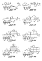
- Figures 4A-4H schematically illustrate the manner in which modules are assembled by the stacker 33.
- Figure 4A shows downstream portions of conveyor 23, several containers 21, the container latching means 37 illustrated schematically at C , the conveyor table 45 of the stacker 33, the driven chains 90 and chain sprockets 91, and another set of rollers 92 which, when driven in the directions indicated by the arrows in Figure 4A, transfer items from the base and lid transfer conveyor 31 to the conveyor table 45 of the stacker.
- FIG 4A the initial step in the assembly of a module is illustrated showing containers 21 on conveyor 23 adjacent the container latching means C , as well as a pair of lids 27 being transferred from the conveyor 31 to the conveyor table 45.
- Figure 4B illustrates that once the lids 27 have been completely transferred onto the table 45, the table is elevated to a level approximately one container height above conveyor 23 at which point the container latching means C engage the lids 27 along the openings formed by the L-shaped members 81 which were described with respect to Figure 2.
- the container latching means C are shown as entering in a direction parallel to the movement of conveyor 23, whereas it will be understood that in the embodiments illustrated in Figure 1 and the remainder of the drawings, the container latching means 37 engages containers and lids in the stacker from the direction perpendicular to the direction of movement of conveyor 23.
- the lids 27 are supported by both the container latching means C and the conveyor table 45.
- the table 45 has been lowered to a level equivalent with that of conveyor 23, leaving the lids 27 supported solely by the container latching means C .
- the containers 21 are moved from conveyor 23 onto conveyor 45 in a position directly underneath the lids 27.
- two such containers are shown being aligned with two lids, but that as few as one container and lid or alternatively several containers and lids can be matched depending upon the size and arrangement of the particular stacker 33.
- the table 45 is raised so that the containers 21 engage the lids 27.
- the container latching means C are released so that the lids and containers are supported solely by the table 45.
- the table 45 is then raised a height substantially equivalent to the height of one container at which time the container latching means C engage the containers rather than the lids which are now supported by the containers.
- Figure 4D illustrates three pairs of containers being supported and lifted by the table 45 while the container latching means C are disengaged.
- Figure 4D shows three containers so engaged by the table 45
- Figure 4E shows a later step in the sequence in which five of the containers, which typically make up a module, have been so elevated and supported by the table 45.
- the container latching means C support the entire stack of containers while the table 45 is lowered to a level coplanar with the base and lid transfer conveyor 31 and receives a pair of bases 30 from the conveyor 31.
- the table 45 is then raised until the bases 30 engage the stack of containers 21 and lids 27 to form a pair of completed modules 20.
- the container latching means is then disengaged for the last time, the table 45 is lowered to a position coplanar with the conveyor 23 and the completed modules exit the stacker 33 for reuse in poultry harvesting operations.
- destacker 24 of the present invention is shown in somewhat greater detail in Figure 5.
- destacker 24 includes an elevatable conveyor table 26 which is shown in detail in Figure 6.
- the table 26 is supported for vertical movement by means shown as the chains 93, at least one of which supports each of the four corners of the table 26.
- Table 26 is formed from two channel-shaped members 103 which support a series of rollers 94, enough of which are driven so as to be able to move modules 20 onto table 26 and then successively move bases 30, containers 21, and lids 20 off of the table 26 during the respective sequence of operations described with respect to Figures 3A-3H.
- the chains 93 are driven around various sprockets 95 by the hydraulic rams 96 which are shown positioned uprightly adjacent two of the chains 93 on adjacent corners of the destacker 24.
- the illustrated embodiment includes bordering portions of box girders 97 which include interspersed openings 100 which permit the dogs 101 of the container latching means 25 to pass through and engage the containers 21 in the opening 75, or the lids 27 underneath the L-shaped members 81.
- Figure 6 also shows sensing means illustrated as the metal proximity detectors 102. With such detectors in place, and in other locations as will be described herein, the stacking and destacking operations of the present invention can be automated as the detectors read the presence or absence of objects on the table 26, and in particular embodiments, can distinguish between the presence of containers 21 and lids or bases 27 and 30, respectively.
- sensing means illustrated as the metal proximity detectors 102.
- Figure 5 additionally illustrates features which have been previously described including the driven chains 90, and the chain sprockets 91 of the lid and base transfer conveyor 31, as well as the additional rollers 92 onto which lids 27 and bases 30 are initially conveyed from the table 26.
- Figure 5 illustrates that the rollers 92 are supported in an appropriate framework 104.
- FIG. 5 Certain features of the container latching means 25 are also illustrated in Figure 5. These include the dogs 101 and the cylinders 105 upon which the dogs rotate in a manner which will be described more thoroughly with respect to Figure 8. As in the other illustrations, a stack of five containers 21, a lid 27 and a base 30 are illustrate as making up the complete modules 20.
- the four chains 93 illustrated in Figure 5 are driven by the hydraulic rams 96, and because the table as illustrated is supported by four such chains, the table is maintained in a level position as it is moved between its various positions.
- the partial plan view of Figure 7 illustrates that two sets of dogs are used on each respective side of each respective module 20 to engage and support the containers 21.
- a set of dogs 101 is illustrated for each container in the stack up to a stack of five containers.
- only the bottommost container need be supported by the dogs and the remaining containers can be supported by the dog-supported lowest container.
- the use of an additional set of dogs 101 for each container being supported has been found to be useful because at this position the individual containers are filled with poultry, making the modules quite heavier than they are when empty.
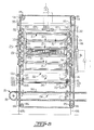
- FIG. 7 is an elevational view taken generally along arrow 7 of Figure 5 and illustrates further details of the destacker 24.
- the destacker includes a framework generally indicated at 105 typically formed of metal portions.
- the conveyor table 26 is suspended within the framework 105 on chains 93 which are in turn operated by the hydraulic cylinders 96.
- Each of the cylinders 96 has a piston arom 106 which in turn is fastened to the chain 93 by the linkage 107.
- piston arm 106 is extended from or alternatively retracted back into hydraulic cylinder 96, it moves chains 93 around their respective sprockets 95 and moves the conveyor table 26 upwardly and downwardly.
- Figure 7 illustrates that the rollers in conveyor table 26 may be driven by a motor 110 which drives belt 111 which in turn drives belt 112 which in turn drives the rollers 94 on the table 26.
- the driven rollers 94 move the containers on table 26 onto the downstream portions of conveyor 23 and then the table 26 is in its lowermost position, moves the lid and base portions 27 and 30, respectively, onto the base and lid transfer conveyor 31.
- the destacker 24 is illustrated as carrying two modules 20 of five containers 21 each, and in the particular illustration, the base portions of the modules 20 have been removed, and the conveyor table 26 lowered to the position coplanar with the loading conveyor 23 so that each group of five containers 21 is supported by the container latching means which has heretofore been broadly designated as 25.
- Figure 7 more clearly illustrates the position of the dogs 101 of which several, but for the sake of clarity not all, have been labelled with reference numerals.
- the dogs are carried by rotatable members 113 in a relationship which is further illustrated in Figure 10.
- Figure 10 illustrates how the dogs 101 are positioned on the rotatable members 113 so that when the rotatable members 113 are rotated, the dogs 101 will pivot into or out of engagement with the openings 75 in the panel portions 74 of the end walls 47 and 50 of a container 21.
- Figure 7 also shows some additional details including axles 114 between the respective sprockets 95 of the chain 93, the box girders 97 along the parallel side edges of the conveyor table 26 and the openings 100 in the box girders 97 which provide room for the dogs 101 to pivot into the containers 21 when the containers are initially supported by the table 26.
- Figure 7 also illustrates the metal proximity detectors 102 described earlier with reference to Figure 6, and in addition show two further metal proximity detectors 115, one of which is shown in somewhat greater detail in Figure 10. As seen in Figure 10, the metal detector 115 is positioned just above the lowermost rotatable member 113 which places it in a position to detect the proximity of a cage 21 when that cage is in the lowermost position in the stack.
- metal proximity detector 115 is positioned to read the proximity of the upper framework member 63 in the container 21 rather than the lower framework member 62. In this manner, the position of metal proximity detector 115 enables it to discriminate between containers 21 and lids 27 or bases 30 which do not have the same vertical dimensions as the containers.
- the position of metal proximity detectors 102 on conveyor table 26 is adjacent to the surface of the rollers 94 so that all items on the table 26, whether containers 21, lids 27 or bases 30, are all detected by detectors 102.
- the output from respective detectors 102 and 115 thus provides a method of discrimination between the items which are being destacked, so that when an item on table 26 is detected by detectors 102, but has not been previously detected by detector 115, the destacker 24 can be programmed to recognize that such an item is either a lid or a base, and that table 26 must be lowered to a position coplanar with base and lid transfer conveyor 31.
- the destacker 24 can be programmed to recognize that a container is being detected, and that the table 26 should accordingly be lowered to a position coplanar with conveyor 23 along which the containers are intended to be moved.
- Figure 10 also shows a further structural feature of the destacker 24.
- box girder 116 is a part of the stationary framework 105 of the destacker and supports a bracket 117 which in turn supports the metal proximity detector 115 in its proper stationary position and carries detector wiring 120 as well.
- Figure 10 also illustrates an adjustment mechanism for leveling the table 26 shown in the form of the threaded member 121 and the adjustment nuts 122 which permit the threaded member to be adjusted and consequently the entire table 26 leveled.
- the threaded member 121 passes through a small bracket 123 which in turn is fixed to the channel member 103 which forms border portions of the table 26.
- Figure 10 also illustrates how the rollers 94 may be carried by the table 26, namely on small axles 124 which can be secured by nuts 125 to the channel member 103.
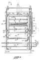
- Figure 8 shows a stack of five containers 21 in the destacker 24.
- Figure 8 illustrates the means for operating the container latching means 25, and shown as the hydraulic ram 126.
- the ram 126 operates oppositely extending arms 127 which are pivotally linked through pivot arm 130 to vertical member 131 and which will raise and lower vertical member 131 as the arms 127 are respectively moved toward the center of the destacker or moved toward the framework.
- Vertical member 131 is in turn pivotally connected through pivot arms 132 to rotatable members 113. When vertical member 131 is raised or lowered by the operation of the hydraulic ram 126, the rotatable members 113 are in turn pivoted so that the dogs 101 engage or disengage from the containers 21 in a manner which has been described previously herein.
- Figure 8 does, however, again illustrate the three respective positions of the conveyor table 26 and in particular illustrates the table 26 in solid lines in its uppermost position engaging a stack of containers, and then also illustrates table 26 in broken lines at its two other respective positions coplanar with the loading conveyor 23 and coplanar with the lid and base transfer conveyor 31, repsectively.
- FIG 9 is a cross-sectional view of the stacker 33.
- the operation and sequencing of the stacker 33 has already been described with respect to Figures 4A-4H, and it will be understood that many of the mechanical details are essentially identical to those of the destacker which has been described with respect to Figures 5, 6, 7, 8, 10 and 11. There are some differences, however, which will be described with reference to Figure 9.
- the framework of stacker 33 is generally indicated at 133.
- the conveyor table for stacker 33 is generally indicated at 45 and shown in its position coplanar with loading conveyor 23 and correspondingly somewhat above lid and base transfer conveyor 31 and somewhat below the position that it can occupy when supporting a stack of containers 21.
- the container latching means 37 of stacker 33 is similar in principle, but mechanically contains fewer parts than the corresponding container latching means 25 of the destacker 24. As set forth earlier, because the containers 21 are empty when they are being manipulated by the stacker 33, the total weight which must be supported by the container latching means 37 is much less than that which must be supported by the container latching means 25 of the destacker when the containers 21 are full of poultry.
- Figure 9 shows that container latching means 37 are also operated by a hydraulic ram 134 and its arms 135. These are pivotally connected through pivot members 136 to the upright members 137. As the ram 134 moves arms 135 respectively outwardly or inwardly, the vertical member 137 is correspondingly raised and lowered and in turn pivots members 140.
- the table 45 of stacker 33 is of similar construction and operation of that of conveyor table 26 of the destacker and can include a motor for driving the conveyor rollers on the table 45.
- Figure 9 illustrates that the stacker likewise includes metal proximity detectors 102 and 115, respectively, which operate in a manner identical with the previously described and which in conjunction with one another can identify whether a container, or alternatively a lid or a base, is proximate the detectors.
- Figure 9 also illustrates that the table 45 can be raised and lowered through the operation of a hydraulic cylinder 41 and piston 42 which are positioned vertically adjacent the framework 133 as also shown in Figure 1.
- the hydraulic cylinder 41 drives chains 43 around respective sprockets 44 to raise and lower table 45 to its respective positions.
- Figures 8 and 9 illustrate that the various hydraulic cylinders and pistons may be controlled by appropriate conventional electrical controls V shown in broken lines in both Figure 8 and Figure 9.
Applications Claiming Priority (2)
| Application Number | Priority Date | Filing Date | Title |
|---|---|---|---|
| US14941588A | 1988-01-29 | 1988-01-29 | |
| US149415 | 1998-09-08 |
Publications (2)
| Publication Number | Publication Date |
|---|---|
| EP0326422A2 true EP0326422A2 (fr) | 1989-08-02 |
| EP0326422A3 EP0326422A3 (fr) | 1989-09-20 |
Family
ID=22530168
Family Applications (1)
| Application Number | Title | Priority Date | Filing Date |
|---|---|---|---|
| EP89300835A Withdrawn EP0326422A3 (fr) | 1988-01-29 | 1989-01-27 | Conteneur de volaille et système pour le désempilage, le déchargement et l'empilage du conteneur |
Country Status (5)
| Country | Link |
|---|---|
| EP (1) | EP0326422A3 (fr) |
| JP (1) | JPH02150221A (fr) |
| AU (1) | AU2884389A (fr) |
| IL (1) | IL89090A0 (fr) |
| ZA (1) | ZA89704B (fr) |
Cited By (18)
| Publication number | Priority date | Publication date | Assignee | Title |
|---|---|---|---|---|
| FR2699900A1 (fr) * | 1992-12-31 | 1994-07-01 | Pelem Sa Electromecanique | Système de déchargement de conteneurs dans lesquels sont placés des bacs contenant des volailles. |
| FR2716073A1 (fr) * | 1994-02-15 | 1995-08-18 | Puissant Alain | Epandeur et automoteur à poussins. |
| US6443102B1 (en) | 1999-07-05 | 2002-09-03 | Schepers Beheer B.V. | Apparatus and method for loading poultry into containers |
| WO2009092166A1 (fr) * | 2008-01-23 | 2009-07-30 | Kl Products Inc. | Désempiler et rempiler des récipients à l'aide d'un robot lors d'opérations d'incubation de volaille |
| ITTO20130395A1 (it) * | 2013-05-16 | 2014-11-17 | Massimo Zanotti | Impianto per la manipolazione di pollame vivo in un macello |
| ITTO20130899A1 (it) * | 2013-11-05 | 2015-05-06 | Massimo Zanotti | Sistema di manipolazione di unita' di trasporto di pollame vivo in un impianto di macellazione |
| CN104609198A (zh) * | 2015-02-02 | 2015-05-13 | 广运机电(苏州)有限公司 | 货物传输移载收集系统 |
| CN104969877A (zh) * | 2015-07-12 | 2015-10-14 | 邵红英 | 带诱虫灯的鸟笼 |
| WO2016064270A1 (fr) * | 2014-10-23 | 2016-04-28 | Marel Stork Poultry Processing B.V. | Base de conteneur, segment de conteneur, couvercle de conteneur et ensemble conteneur pour contenir de la volaille vivante, et procédé de chargement et de déchargement d'un tel ensemble conteneur |
| NL2013674B1 (en) * | 2014-10-23 | 2016-10-06 | Marel Stork Poultry Proc Bv | Container base, container segment and container assembly for holding live poultry and method for loading and unloading such a container assembly. |
| NL2014757A (en) * | 2015-05-01 | 2016-11-07 | Marel Stork Poultry Proc Bv | Containter base, container segment, container cover and container assembly for holding live poultry and method for loading and unloading such a container assembly. |
| CN107758360A (zh) * | 2017-10-19 | 2018-03-06 | 国网天津市电力公司电力科学研究院 | 一种窄带电力载波模块检测的自动化接驳方法 |
| CN107758359A (zh) * | 2017-10-19 | 2018-03-06 | 国网天津市电力公司电力科学研究院 | 一种宽带电力载波模块检测的自动化接驳方法 |
| US10660314B2 (en) | 2014-02-05 | 2020-05-26 | Linco Food Systems A/S | Broiler container with a base and side walls, which is designed and set up for receiving and holding at least five living broilers, in particular as part of a unit and an arrangement of a transport trailer |
| CN111217113A (zh) * | 2020-02-17 | 2020-06-02 | 浙江捷创智能技术有限公司 | 一种周转箱上料装置及上料方法 |
| CN113320992A (zh) * | 2021-04-28 | 2021-08-31 | 国网湖南省电力有限公司 | 双通道拆叠垛机及拆叠垛方法 |
| KR20220118562A (ko) * | 2015-04-15 | 2022-08-25 | 오카도 이노베이션 리미티드 | 보관 시스템 및 방법 |
| KR20220146709A (ko) * | 2016-10-19 | 2022-11-01 | 오카도 이노베이션 리미티드 | 보관 시스템 및 방법 |
Families Citing this family (3)
| Publication number | Priority date | Publication date | Assignee | Title |
|---|---|---|---|---|
| KR20030048267A (ko) * | 2001-12-11 | 2003-06-19 | 유도실업주식회사 | 사출기용 노즐의 고화 방지장치 |
| JP2006044826A (ja) * | 2004-07-30 | 2006-02-16 | Gordex Kk | 生鳥籠取扱装置 |
| CN106035134A (zh) * | 2016-07-01 | 2016-10-26 | 青岛牧羊人畜牧工程有限公司 | 一种分流斜向出鸡系统 |
Citations (7)
| Publication number | Priority date | Publication date | Assignee | Title |
|---|---|---|---|---|
| US3891097A (en) * | 1973-07-06 | 1975-06-24 | Us Agriculture | Chicken coop unstacking machine |
| DE2839412A1 (de) * | 1978-09-11 | 1980-03-13 | Schenck Ag Carl | Verfahren und vorrichtung zum speichern oder entspeichern von tragrahmen |
| GB2050309A (en) * | 1979-05-30 | 1981-01-07 | Sun Valley Poultry | Methods of handling livestock |
| EP0061869A1 (fr) * | 1981-04-01 | 1982-10-06 | Anglia Autoflow Limited | Système de transport pour menu bétail, et son appareillage |
| US4355939A (en) * | 1979-12-27 | 1982-10-26 | Musgrave Harry J | Palletized poultry coop handling system |
| US4602594A (en) * | 1983-11-28 | 1986-07-29 | Den Brink Hendrikus G Van | Device for packing poultry in boxes or containers |
| DE3616889A1 (de) * | 1985-05-20 | 1986-11-20 | Oki Electric Industry Co., Ltd., Tokio/Tokyo | Vorrichtung und verfahren zur automatischen handhabung von teilen |
-
1989
- 1989-01-23 JP JP1013896A patent/JPH02150221A/ja active Pending
- 1989-01-26 IL IL89090A patent/IL89090A0/xx unknown
- 1989-01-26 AU AU28843/89A patent/AU2884389A/en not_active Abandoned
- 1989-01-27 ZA ZA89704A patent/ZA89704B/xx unknown
- 1989-01-27 EP EP89300835A patent/EP0326422A3/fr not_active Withdrawn
Patent Citations (7)
| Publication number | Priority date | Publication date | Assignee | Title |
|---|---|---|---|---|
| US3891097A (en) * | 1973-07-06 | 1975-06-24 | Us Agriculture | Chicken coop unstacking machine |
| DE2839412A1 (de) * | 1978-09-11 | 1980-03-13 | Schenck Ag Carl | Verfahren und vorrichtung zum speichern oder entspeichern von tragrahmen |
| GB2050309A (en) * | 1979-05-30 | 1981-01-07 | Sun Valley Poultry | Methods of handling livestock |
| US4355939A (en) * | 1979-12-27 | 1982-10-26 | Musgrave Harry J | Palletized poultry coop handling system |
| EP0061869A1 (fr) * | 1981-04-01 | 1982-10-06 | Anglia Autoflow Limited | Système de transport pour menu bétail, et son appareillage |
| US4602594A (en) * | 1983-11-28 | 1986-07-29 | Den Brink Hendrikus G Van | Device for packing poultry in boxes or containers |
| DE3616889A1 (de) * | 1985-05-20 | 1986-11-20 | Oki Electric Industry Co., Ltd., Tokio/Tokyo | Vorrichtung und verfahren zur automatischen handhabung von teilen |
Cited By (36)
| Publication number | Priority date | Publication date | Assignee | Title |
|---|---|---|---|---|
| FR2699900A1 (fr) * | 1992-12-31 | 1994-07-01 | Pelem Sa Electromecanique | Système de déchargement de conteneurs dans lesquels sont placés des bacs contenant des volailles. |
| FR2716073A1 (fr) * | 1994-02-15 | 1995-08-18 | Puissant Alain | Epandeur et automoteur à poussins. |
| US6443102B1 (en) | 1999-07-05 | 2002-09-03 | Schepers Beheer B.V. | Apparatus and method for loading poultry into containers |
| US9232773B2 (en) | 2008-01-23 | 2016-01-12 | Kl Products Inc. | Destacking and restacking of containers using a robot in poultry hatchery operations |
| WO2009092166A1 (fr) * | 2008-01-23 | 2009-07-30 | Kl Products Inc. | Désempiler et rempiler des récipients à l'aide d'un robot lors d'opérations d'incubation de volaille |
| US10098330B2 (en) | 2008-01-23 | 2018-10-16 | Zoetis Canada Inc. | Destacking and restacking of containers using a robot in poultry hatchery operations |
| ITTO20130395A1 (it) * | 2013-05-16 | 2014-11-17 | Massimo Zanotti | Impianto per la manipolazione di pollame vivo in un macello |
| EP2803263A1 (fr) * | 2013-05-16 | 2014-11-19 | Massimo Zanotti | Installation pour la manipulation de volaille dans un abbatoir |
| WO2014184693A1 (fr) * | 2013-05-16 | 2014-11-20 | Massimo Zanotti | Installation pour manipuler des volailles vivantes dans un abattoir |
| EP2868202A1 (fr) * | 2013-11-05 | 2015-05-06 | Massimo Zanotti | Système de traitement d'unités de transport de volailles vivantes dans un abattoir |
| WO2015068014A1 (fr) * | 2013-11-05 | 2015-05-14 | Massimo Zanotti | Système de manutention pour des unités de transport de volailles vivantes dans un abattoir |
| US20150125243A1 (en) * | 2013-11-05 | 2015-05-07 | Massimo Zanotti | Handling system for transport units of live poultry in a slaughterhouse |
| US10618754B2 (en) | 2013-11-05 | 2020-04-14 | Massimo Zanotti | Handling system for transport units of live poultry in a slaughterhouse |
| ITTO20130899A1 (it) * | 2013-11-05 | 2015-05-06 | Massimo Zanotti | Sistema di manipolazione di unita' di trasporto di pollame vivo in un impianto di macellazione |
| US11166438B2 (en) | 2014-02-05 | 2021-11-09 | Linco Food Systems A/S | Broiler container with a base and side walls, which is designed and set up for receiving and holding at least five living broilers, in particular as part of a unit, and an arrangement of a transport trailer |
| US10912284B2 (en) | 2014-02-05 | 2021-02-09 | Linco Food Systems A/S | Broiler container with a base and side walls, which is designed and set up for receiving and holding at least five living broilers, in particular as part of a unit, and an arrangement of a transport trailer |
| US10660314B2 (en) | 2014-02-05 | 2020-05-26 | Linco Food Systems A/S | Broiler container with a base and side walls, which is designed and set up for receiving and holding at least five living broilers, in particular as part of a unit and an arrangement of a transport trailer |
| CN107105629A (zh) * | 2014-10-23 | 2017-08-29 | 马雷尔斯托克家禽加工有限公司 | 用于容纳活家禽的容器基部、容器区段、容器盖和容器组件以及用于装载和卸载这种容器组件的方法 |
| US11026405B2 (en) | 2014-10-23 | 2021-06-08 | Marel Stork Poultry Processing B.V. | Container base, container segment, container cover and container assembly for holding live poultry and method for loading and unloading such a container assembly |
| KR102617555B1 (ko) | 2014-10-23 | 2023-12-26 | 마렐 폴트리 비.브이. | 살아있는 가금류를 수용하기 위한 콘테이너 베이스, 콘테이너 세그먼트, 콘테이너 커버 및 콘테이너 조립체 및 이러한 콘테이너 조립체를 적재 및 하역하기 위한 방법 |
| CN113080096A (zh) * | 2014-10-23 | 2021-07-09 | 马雷尔斯托克家禽加工有限公司 | 用于容纳活家禽的容器区段 |
| KR20170084053A (ko) * | 2014-10-23 | 2017-07-19 | 마렐 스토크 폴트리 프로세싱 비.브이. | 살아있는 가금류를 수용하기 위한 콘테이너 베이스, 콘테이너 세그먼트, 콘테이너 커버 및 콘테이너 조립체 및 이러한 콘테이너 조립체를 적재 및 하역하기 위한 방법 |
| NL2013674B1 (en) * | 2014-10-23 | 2016-10-06 | Marel Stork Poultry Proc Bv | Container base, container segment and container assembly for holding live poultry and method for loading and unloading such a container assembly. |
| WO2016064270A1 (fr) * | 2014-10-23 | 2016-04-28 | Marel Stork Poultry Processing B.V. | Base de conteneur, segment de conteneur, couvercle de conteneur et ensemble conteneur pour contenir de la volaille vivante, et procédé de chargement et de déchargement d'un tel ensemble conteneur |
| CN104609198A (zh) * | 2015-02-02 | 2015-05-13 | 广运机电(苏州)有限公司 | 货物传输移载收集系统 |
| KR20220118562A (ko) * | 2015-04-15 | 2022-08-25 | 오카도 이노베이션 리미티드 | 보관 시스템 및 방법 |
| KR102637050B1 (ko) | 2015-04-15 | 2024-02-14 | 오카도 이노베이션 리미티드 | 보관 시스템 및 방법 |
| NL2014757A (en) * | 2015-05-01 | 2016-11-07 | Marel Stork Poultry Proc Bv | Containter base, container segment, container cover and container assembly for holding live poultry and method for loading and unloading such a container assembly. |
| CN104969877A (zh) * | 2015-07-12 | 2015-10-14 | 邵红英 | 带诱虫灯的鸟笼 |
| KR20220146709A (ko) * | 2016-10-19 | 2022-11-01 | 오카도 이노베이션 리미티드 | 보관 시스템 및 방법 |
| KR102585087B1 (ko) | 2016-10-19 | 2023-10-05 | 오카도 이노베이션 리미티드 | 보관 시스템 및 방법 |
| CN107758359A (zh) * | 2017-10-19 | 2018-03-06 | 国网天津市电力公司电力科学研究院 | 一种宽带电力载波模块检测的自动化接驳方法 |
| CN107758360A (zh) * | 2017-10-19 | 2018-03-06 | 国网天津市电力公司电力科学研究院 | 一种窄带电力载波模块检测的自动化接驳方法 |
| CN111217113A (zh) * | 2020-02-17 | 2020-06-02 | 浙江捷创智能技术有限公司 | 一种周转箱上料装置及上料方法 |
| CN111217113B (zh) * | 2020-02-17 | 2021-10-22 | 浙江捷创智能技术有限公司 | 一种周转箱上料装置及上料方法 |
| CN113320992A (zh) * | 2021-04-28 | 2021-08-31 | 国网湖南省电力有限公司 | 双通道拆叠垛机及拆叠垛方法 |
Also Published As
| Publication number | Publication date |
|---|---|
| JPH02150221A (ja) | 1990-06-08 |
| IL89090A0 (en) | 1989-08-15 |
| ZA89704B (en) | 1989-10-25 |
| EP0326422A3 (fr) | 1989-09-20 |
| AU2884389A (en) | 1989-08-03 |
Similar Documents
| Publication | Publication Date | Title |
|---|---|---|
| EP0326422A2 (fr) | Conteneur de volaille et système pour le désempilage, le déchargement et l'empilage du conteneur | |
| US20050002772A1 (en) | Mail container handling system | |
| US5505582A (en) | Apparatus and method for unloading content of multilayer containers | |
| EP0296601A1 (fr) | Appareil pour désempiler et empiler des conteneurs | |
| US20080014074A1 (en) | Off-the-bottom Depalletizer apparatus and method | |
| US20220143810A1 (en) | Automated System For Handling Containers With Product Loading | |
| US20230011190A1 (en) | Stacking and packaging device | |
| US3917082A (en) | Destacking apparatus | |
| US6564528B1 (en) | Method and apparatus for bagging potatoes | |
| CN111632846A (zh) | 一种铁块智能分拣系统及其分拣方法 | |
| EP0005755A1 (fr) | Container et procédé de transport | |
| US5797716A (en) | Container contents unloading apparatus for unloading contents of a container and method of unloading same | |
| CZ2020701A3 (cs) | Stoh svázaných sloupců složených stohovatelných přepravek, způsob jeho strojového rozebírání a zařízení k provádění tohoto způsobu | |
| US4285299A (en) | Method and apparatus for collecting poultry | |
| US3777710A (en) | Automated systems for raising and transporting broilers | |
| WO2001002275A1 (fr) | Appareil destine a empiler ou a depiler des contenants | |
| US3608292A (en) | Collection system for harvesting machines | |
| US6048157A (en) | Turkey coop unloading apparatus and method | |
| US5169283A (en) | Basket denester | |
| US6564752B2 (en) | Poultry coop unloader, and methods | |
| CN209973728U (zh) | 一种饲料袋自动拆垛装置 | |
| US2956697A (en) | Unstacking machine | |
| CN115339916A (zh) | 全自动瓜果卸料装置和方法 | |
| CN212821173U (zh) | 一种铁块智能分拣系统 | |
| SE455302B (sv) | Forfarande och apparatur for transport av plantcellblock pa palletter, vilka travas, och anvendning av apparatur for avlastning av travade cellblockpalletter |
Legal Events
| Date | Code | Title | Description |
|---|---|---|---|
| PUAI | Public reference made under article 153(3) epc to a published international application that has entered the european phase |
Free format text: ORIGINAL CODE: 0009012 |
|
| AK | Designated contracting states |
Kind code of ref document: A2 Designated state(s): DE ES FR GB IT NL |
|
| PUAL | Search report despatched |
Free format text: ORIGINAL CODE: 0009013 |
|
| AK | Designated contracting states |
Kind code of ref document: A3 Designated state(s): DE ES FR GB IT NL |
|
| STAA | Information on the status of an ep patent application or granted ep patent |
Free format text: STATUS: THE APPLICATION IS DEEMED TO BE WITHDRAWN |
|
| 18D | Application deemed to be withdrawn |
Effective date: 19900321 |