EP0326044B1 - Einrichtung zur Ausregelung von Luftdruckstössen in Fahrgasträumen von Schienenfahrzeugen - Google Patents
Einrichtung zur Ausregelung von Luftdruckstössen in Fahrgasträumen von Schienenfahrzeugen Download PDFInfo
- Publication number
- EP0326044B1 EP0326044B1 EP89101016A EP89101016A EP0326044B1 EP 0326044 B1 EP0326044 B1 EP 0326044B1 EP 89101016 A EP89101016 A EP 89101016A EP 89101016 A EP89101016 A EP 89101016A EP 0326044 B1 EP0326044 B1 EP 0326044B1
- Authority
- EP
- European Patent Office
- Prior art keywords
- air
- sensors
- control circuit
- fan
- passenger compartment
- Prior art date
- Legal status (The legal status is an assumption and is not a legal conclusion. Google has not performed a legal analysis and makes no representation as to the accuracy of the status listed.)
- Expired - Lifetime
Links
- 238000009499 grossing Methods 0.000 title claims abstract 3
- 230000004308 accommodation Effects 0.000 title 1
- 230000035939 shock Effects 0.000 title 1
- 238000004378 air conditioning Methods 0.000 claims abstract description 8
- 238000009423 ventilation Methods 0.000 claims 5
- 238000005259 measurement Methods 0.000 claims 1
- 238000010276 construction Methods 0.000 abstract 1
- 239000003990 capacitor Substances 0.000 description 4
- 230000001105 regulatory effect Effects 0.000 description 4
- 239000012528 membrane Substances 0.000 description 3
- 230000035945 sensitivity Effects 0.000 description 3
- 230000001276 controlling effect Effects 0.000 description 2
- 238000010586 diagram Methods 0.000 description 1
- 230000001771 impaired effect Effects 0.000 description 1
Images
Classifications
-
- B—PERFORMING OPERATIONS; TRANSPORTING
- B60—VEHICLES IN GENERAL
- B60H—ARRANGEMENTS OF HEATING, COOLING, VENTILATING OR OTHER AIR-TREATING DEVICES SPECIALLY ADAPTED FOR PASSENGER OR GOODS SPACES OF VEHICLES
- B60H1/00—Heating, cooling or ventilating [HVAC] devices
- B60H1/00642—Control systems or circuits; Control members or indication devices for heating, cooling or ventilating devices
- B60H1/00814—Control systems or circuits characterised by their output, for controlling particular components of the heating, cooling or ventilating installation
- B60H1/00821—Control systems or circuits characterised by their output, for controlling particular components of the heating, cooling or ventilating installation the components being ventilating, air admitting or air distributing devices
- B60H1/00828—Ventilators, e.g. speed control
-
- B—PERFORMING OPERATIONS; TRANSPORTING
- B61—RAILWAYS
- B61D—BODY DETAILS OR KINDS OF RAILWAY VEHICLES
- B61D27/00—Heating, cooling, ventilating, or air-conditioning
- B61D27/0009—Means for controlling or equalizing air pressure shocks in trains, e.g. when passing or crossing in tunnels
Definitions
- the invention relates to a device for regulating air pressure surges in passenger compartments of rail vehicles according to the preamble of claim 1.
- Such a device is known from DE-PS 33 43 487, the air pressure surges in the passenger compartments being corrected with the aid of an air conditioning system.
- the air conditioning system has a fresh air inlet and at least one air outlet from the passenger compartment, wherein an essentially constant air flow through the passenger compartment is maintained with the aid of fans, usually an intake fan with a corresponding fan.
- sensors are provided which measure the respective air flow rate, e.g. Speed sensors which are arranged in the fresh air inlet. These sensors work in conjunction with a slave controller, the output signals of which are used to set an aperture that is arranged in the air inlet.
- Document EP-A-0 104 547 shows a device which has a flow regulating flap which can be pivoted by means of an adjusting motor and a built-in blower which can be driven by an electric motor at different speeds.
- the invention has for its object to constructively simplify a device of the type in question, without the effectiveness being impaired.
- the fans of the blowers themselves and to change their speed as the only actuating means for regulating air pressure surges and for setting a substantially constant air flow.
- the speed can be easily influenced using contactors or adjustable electrical resistors.
- the fans with their fans are arranged, the speed of the intake fans, exhaust fans or combined can be controlled by controlling both fans.
- Pressure difference sensors can be used as sensors, the sensor characteristics of which are adapted to the sensitivity of the human ear.
- a conventional slave controller according to the above-mentioned German patent can be used as the controller.
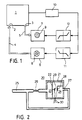
- a passenger compartment 1 of a rail vehicle is connected to at least one air inlet 2 and at least one air outlet 3.
- the air inlets and air outlets are connected to blowers 6 and 7 via air pipes 4 and 5, respectively.
- the blower 6 is a pressure blower with a fan 8, through which fresh air is pressed into the passenger compartment 1.
- the blower 7 is a suction blower with a fan 9, through which the used air is extracted from the passenger compartment 1. Between the air inlet 2 and the air outlet 3, a certain pressure gradient with slight fluctuations in time is to be set, so that an essentially constant amount of air per unit time flows through the passenger compartment 1.
- a sensor arrangement 10 which can consist, for example, of a plurality of sensors in the air inlet 2 and air outlet 3 in accordance with an arrangement in the aforementioned patent specification 33 43 487.
- the pressure gradient within the passenger compartment is measured with this sensor arrangement.
- the time derivative ⁇ M of the pressure within the passenger compartment is used as the control signal in accordance with the cited patent specification and is supplied to two follow-up controllers 11 and 12, which compare the measured pressure gradient with a desired value.
- the controllers 11 and 12 can be designed as conventional follow-up controllers, which have a characteristic curve with a dead zone area around the desired value and then linear branches in the positive and in the negative area.
- the speed of the fans 8 and 9 in the inlet and outlet blowers 6 and 7 is regulated by these slave controllers 11 and 12. If the measured pressure gradient exceeds the positive end value of the dead zone range, the speed of the fan 8 in the inlet fan 6 is reduced accordingly and that of the fan 9 in the outlet fan raised. If the measured pressure gradient falls below the negative value predetermined by the dead zone range, the speed of the inlet fan 8 is increased and that of the outlet fan 9 is reduced accordingly.
- FIG. 1 An embodiment of a sensor 20 of the sensor arrangement 10 for measuring the pressure gradient or the pressure change over time is shown in FIG.
- the sensor 20 has a housing 21 which is divided into two chambers 23 and 24 by a membrane 22.
- An inlet line 25, which has a throttle point 26, is connected to the inlet-side chamber 23. With the chamber 24, an outlet line is connected, which is returned to the inlet line 25 before the throttle point 26.
- a fixed capacitor plate 28 is provided in the outlet-side chamber 24 of the sensor 20, and a second capacitor plate 29, which is moved with the membrane 22, is connected to the membrane 22.
- a voltage is applied between both capacitor plates 28 and 29; the voltage changes caused by the change in distance between the capacitor plates 28 and 29 are detected by tap lines 39.
- the sensor characteristics of this sensor can be adjusted to the sensitivity of the human ear.
- the characteristics of the slave controllers are also adapted to this sensitivity, which in particular determines the controller's dead zone range.
Landscapes
- Engineering & Computer Science (AREA)
- Mechanical Engineering (AREA)
- Physics & Mathematics (AREA)
- Thermal Sciences (AREA)
- Air-Conditioning For Vehicles (AREA)
- Control Of Fluid Pressure (AREA)
- Vehicle Body Suspensions (AREA)
- Air Bags (AREA)
- Fluid-Damping Devices (AREA)
- Ventilation (AREA)
Priority Applications (1)
| Application Number | Priority Date | Filing Date | Title |
|---|---|---|---|
| AT89101016T ATE80584T1 (de) | 1988-01-23 | 1989-01-20 | Einrichtung zur ausregelung von luftdruckstoessen in fahrgastraeumen von schienenfahrzeugen. |
Applications Claiming Priority (2)
| Application Number | Priority Date | Filing Date | Title |
|---|---|---|---|
| DE3801891A DE3801891C1 (enExample) | 1988-01-23 | 1988-01-23 | |
| DE3801891 | 1988-01-23 |
Publications (3)
| Publication Number | Publication Date |
|---|---|
| EP0326044A2 EP0326044A2 (de) | 1989-08-02 |
| EP0326044A3 EP0326044A3 (en) | 1990-01-17 |
| EP0326044B1 true EP0326044B1 (de) | 1992-09-16 |
Family
ID=6345824
Family Applications (1)
| Application Number | Title | Priority Date | Filing Date |
|---|---|---|---|
| EP89101016A Expired - Lifetime EP0326044B1 (de) | 1988-01-23 | 1989-01-20 | Einrichtung zur Ausregelung von Luftdruckstössen in Fahrgasträumen von Schienenfahrzeugen |
Country Status (4)
| Country | Link |
|---|---|
| EP (1) | EP0326044B1 (enExample) |
| AT (1) | ATE80584T1 (enExample) |
| DE (1) | DE3801891C1 (enExample) |
| ES (1) | ES2034410T3 (enExample) |
Families Citing this family (21)
| Publication number | Priority date | Publication date | Assignee | Title |
|---|---|---|---|---|
| DE3884747T2 (de) * | 1987-11-02 | 1994-01-27 | Hitachi Ltd | Lüftungsausrüstung für rollendes Material. |
| DE3940719C1 (enExample) * | 1989-12-09 | 1990-10-04 | Industrieanlagen-Betriebsgesellschaft Mbh, 8012 Ottobrunn, De | |
| EP0448326B1 (en) * | 1990-03-19 | 1996-10-23 | Hitachi, Ltd. | Ventilating equipment for railway rolling stock and operating method thereof |
| DE4100817A1 (de) * | 1991-01-14 | 1992-07-16 | Behr Gmbh & Co | Luftmengen-regelanordnung fuer kraftfahrzeuge |
| TW205538B (enExample) * | 1991-02-08 | 1993-05-11 | Hitachi Seisakusyo Kk | |
| DE69224125T2 (de) * | 1991-09-26 | 1998-08-27 | St Microelectronics Srl | Leseverstärker |
| FR2693698B1 (fr) * | 1992-07-16 | 1994-08-19 | Alsthom Gec | Dispositif de suppression des variations brutales de pression dans les véhicules, en particulier dans les véhicules terrestres. |
| DE4314262A1 (de) * | 1993-04-30 | 1994-11-03 | Krapf & Lex | Vorrichtung zur Druckbegrenzung in schnell fahrenden Schienenfahrzeugen |
| DE4432277A1 (de) * | 1994-09-09 | 1996-03-14 | Hagenuk Fahrzeugklima Gmbh | Druckschutzsystem |
| DE29510523U1 (de) * | 1995-06-29 | 1995-10-05 | Hagenuk Fahrzeugklima GmbH, 04435 Schkeuditz | Druckgeschütztes Lüftungssystem |
| DE19649664C2 (de) * | 1996-11-29 | 1999-12-23 | Hagenuk Faiveley Gmbh | Verfahren und Vorrichtung zur druckgeschützten Belüftung von Hochgeschwindigkeitszügen |
| DE19755097C1 (de) * | 1997-12-11 | 1999-06-17 | Maik Coldewey | Ventilschließ-Spülluft-Druckschutzsystem |
| DE102011081070A1 (de) * | 2011-08-17 | 2013-02-21 | Siemens Aktiengesellschaft | Vorrichtung und Verfahren zur aktiven Druckregelung in Schienenfahrzeugen |
| DE202014104358U1 (de) | 2014-09-15 | 2014-12-12 | Faiveley Transport Leipzig Gmbh & Co. Kg | Vorrichtung für eine kombinierte Druckschutz- und Luftmengenregelung im Innenraum von Schienenfahrzeugen |
| DE102015101522A1 (de) | 2015-02-03 | 2016-08-04 | Faiveley Transport Leipzig Gmbh & Co. Kg | Verfahren zur Regelung von mindestens einem Stellglied eines Druckschutzsystems für ein Schienenfahrzeug |
| DE102015212318A1 (de) * | 2015-07-01 | 2017-01-05 | Siemens Aktiengesellschaft | Verfahren zum Belüften eines gekoppelte Wagen aufweisenden Fahrzeugs |
| DE102015117665A1 (de) * | 2015-10-16 | 2017-04-20 | Bombardier Transportation Gmbh | Vorrichtung zum klimatisieren eines innenraums eines fahrzeugs, insbesondere eines schienenfahrzeugs |
| CN109895800A (zh) | 2017-12-08 | 2019-06-18 | 中车青岛四方机车车辆股份有限公司 | 一种轨道车辆车内压力监控系统和方法 |
| CN109747673B (zh) * | 2019-03-01 | 2021-02-05 | 中车青岛四方机车车辆股份有限公司 | 一种车内压力调节装置及调节方法 |
| CN110723158B (zh) * | 2019-10-24 | 2021-03-23 | 新誉轨道交通科技有限公司 | 一种高速列车压力波保护控制方法、系统及高速列车 |
| CN114194236B (zh) * | 2020-09-18 | 2023-05-12 | 中车青岛四方机车车辆股份有限公司 | 一种轨道车辆开关门控制方法及控制系统 |
Family Cites Families (4)
| Publication number | Priority date | Publication date | Assignee | Title |
|---|---|---|---|---|
| US2753515A (en) * | 1952-09-03 | 1956-07-03 | Edward J Rickner | Capacitor type differential pressure switch |
| DE2658882A1 (de) * | 1976-12-24 | 1978-06-29 | Bbc Brown Boveri & Cie | Reisezugwagen mit klimaanlage |
| DE3235162A1 (de) * | 1982-09-23 | 1984-03-29 | Robert Bosch Gmbh, 7000 Stuttgart | Lueftungs-, insbesondere klimaanlage fuer ein fahrzeug |
| DE3343487A1 (de) * | 1983-12-01 | 1985-06-13 | Messerschmitt-Bölkow-Blohm GmbH, 8012 Ottobrunn | Einrichtung zur belueftung und klimatisierung von fahrgastraeumen in schienenfahrzeugen |
-
1988
- 1988-01-23 DE DE3801891A patent/DE3801891C1/de not_active Expired
-
1989
- 1989-01-20 ES ES198989101016T patent/ES2034410T3/es not_active Expired - Lifetime
- 1989-01-20 EP EP89101016A patent/EP0326044B1/de not_active Expired - Lifetime
- 1989-01-20 AT AT89101016T patent/ATE80584T1/de active
Also Published As
| Publication number | Publication date |
|---|---|
| DE3801891C1 (enExample) | 1989-09-07 |
| EP0326044A2 (de) | 1989-08-02 |
| EP0326044A3 (en) | 1990-01-17 |
| ATE80584T1 (de) | 1992-10-15 |
| ES2034410T3 (es) | 1993-04-01 |
Similar Documents
| Publication | Publication Date | Title |
|---|---|---|
| EP0326044B1 (de) | Einrichtung zur Ausregelung von Luftdruckstössen in Fahrgasträumen von Schienenfahrzeugen | |
| EP0314675B1 (de) | Verfahren zum betreiben einer heiz- und/oder klimaanlage für kraftfahrzeuge | |
| DE1961438C3 (de) | Drehzahlsteuerungseinrichtung für eine Kraftmaschine zur Steuerung der Leerlaufdrehzahl | |
| EP0314674B1 (de) | Heiz- und/oder klimaanlage für kraftfahrzeuge | |
| EP0428523B1 (de) | Klimatisierungseinrichtung für kraftfahrzeuge | |
| DE102015218474A1 (de) | Innenraumbelüftungssystem für ein Kraftfahrzeug | |
| DE2149548B2 (de) | Klimaanlage für Eisenbahnfahrzeuge | |
| DE3447896C2 (enExample) | ||
| EP0495201B1 (de) | Luftmengen-Regelanordnung für Kraftfahrzeuge | |
| EP0143931B1 (de) | Einrichtung zur Belüftung und Klimatisierung von Fahrgasträumen in Schienenfahrzeugen | |
| DE3884255T2 (de) | Messschaltung zur Verwendung in einer Vorrichtung zur Erfassung der Umgebungslufttemperatur. | |
| EP0802076A2 (de) | Verfahren zum Betrieb einer Heizungs- und/oder Klimaanlage | |
| DE4414707C2 (de) | Verfahren und Vorrichtung für die Durchflußregelung eines Luftstroms | |
| EP0968858A1 (de) | Luftzuführungseinrichtung und Verfahren zur Regelung der Luftzuführung in einem Fahrzeug | |
| DE102014016503A1 (de) | Verfahren zur Bestimmung des Druckabfalles an einem Luftfilter einer Fahrzeugklimaanlage | |
| DE3535118C2 (de) | Verfahren zur Analog-Digital-Wandlung von analogen Spannungen | |
| EP0508068B1 (de) | Vorrichtung zur Regelung der Ladelufttemperatur einer Brennkraftmaschine in Abhängigkeit von der Tautemperatur der Ladeluft | |
| EP0385395A2 (de) | Stellvorrichtung für die Lamellen eines Luftheiz-,Luftkühl-, oder Belüftungsgerätes | |
| DE10036502C1 (de) | Klimaanlage für ein Fahrzeug | |
| DE19936643C2 (de) | Vorrichtung zur Klimatisierung des Kabinenbereiches eines Passagierflugzeuges | |
| EP0381846A2 (de) | Einrichtung zur Temperaturregelung im Innenraum von Kraftfahrzeugen | |
| DE102016015261B4 (de) | Verfahren zum Betreiben einer Fahrzeug-Klimaanlage mit einem Klimagerät | |
| EP0410162B1 (de) | Einrichtung zur Seitenruder-Trimmung | |
| DE102016125221A1 (de) | Klimaanlage mit Erkennung der Luftfilterbeladung | |
| EP0847887A2 (de) | Mehrkanalige Heiz- oder Klimaanlage |
Legal Events
| Date | Code | Title | Description |
|---|---|---|---|
| PUAI | Public reference made under article 153(3) epc to a published international application that has entered the european phase |
Free format text: ORIGINAL CODE: 0009012 |
|
| AK | Designated contracting states |
Kind code of ref document: A2 Designated state(s): AT CH ES FR GB IT LI NL |
|
| PUAL | Search report despatched |
Free format text: ORIGINAL CODE: 0009013 |
|
| AK | Designated contracting states |
Kind code of ref document: A3 Designated state(s): AT CH ES FR GB IT LI NL |
|
| 17P | Request for examination filed |
Effective date: 19900402 |
|
| RAP1 | Party data changed (applicant data changed or rights of an application transferred) |
Owner name: MAN GHH SCHIENENVERKEHRSTECHNIK GMBH |
|
| RAP1 | Party data changed (applicant data changed or rights of an application transferred) |
Owner name: MAN GHH SCHIENENVERKEHRSTECHNIK GMBH |
|
| 17Q | First examination report despatched |
Effective date: 19911004 |
|
| GRAA | (expected) grant |
Free format text: ORIGINAL CODE: 0009210 |
|
| AK | Designated contracting states |
Kind code of ref document: B1 Designated state(s): AT CH ES FR GB IT LI NL |
|
| REF | Corresponds to: |
Ref document number: 80584 Country of ref document: AT Date of ref document: 19921015 Kind code of ref document: T |
|
| ET | Fr: translation filed | ||
| GBT | Gb: translation of ep patent filed (gb section 77(6)(a)/1977) | ||
| ITF | It: translation for a ep patent filed | ||
| REG | Reference to a national code |
Ref country code: ES Ref legal event code: FG2A Ref document number: 2034410 Country of ref document: ES Kind code of ref document: T3 |
|
| PLBE | No opposition filed within time limit |
Free format text: ORIGINAL CODE: 0009261 |
|
| STAA | Information on the status of an ep patent application or granted ep patent |
Free format text: STATUS: NO OPPOSITION FILED WITHIN TIME LIMIT |
|
| 26N | No opposition filed | ||
| PGFP | Annual fee paid to national office [announced via postgrant information from national office to epo] |
Ref country code: GB Payment date: 19931213 Year of fee payment: 6 Ref country code: CH Payment date: 19931213 Year of fee payment: 6 |
|
| PGFP | Annual fee paid to national office [announced via postgrant information from national office to epo] |
Ref country code: FR Payment date: 19931221 Year of fee payment: 6 |
|
| PGFP | Annual fee paid to national office [announced via postgrant information from national office to epo] |
Ref country code: AT Payment date: 19931228 Year of fee payment: 6 |
|
| PGFP | Annual fee paid to national office [announced via postgrant information from national office to epo] |
Ref country code: ES Payment date: 19940120 Year of fee payment: 6 |
|
| PGFP | Annual fee paid to national office [announced via postgrant information from national office to epo] |
Ref country code: NL Payment date: 19940131 Year of fee payment: 6 |
|
| PG25 | Lapsed in a contracting state [announced via postgrant information from national office to epo] |
Ref country code: GB Effective date: 19950120 Ref country code: AT Effective date: 19950120 |
|
| PG25 | Lapsed in a contracting state [announced via postgrant information from national office to epo] |
Ref country code: ES Free format text: LAPSE BECAUSE OF NON-PAYMENT OF DUE FEES Effective date: 19950121 |
|
| PG25 | Lapsed in a contracting state [announced via postgrant information from national office to epo] |
Ref country code: LI Effective date: 19950131 Ref country code: CH Effective date: 19950131 |
|
| PG25 | Lapsed in a contracting state [announced via postgrant information from national office to epo] |
Ref country code: NL Effective date: 19950801 |
|
| GBPC | Gb: european patent ceased through non-payment of renewal fee |
Effective date: 19950120 |
|
| PG25 | Lapsed in a contracting state [announced via postgrant information from national office to epo] |
Ref country code: FR Effective date: 19950929 |
|
| REG | Reference to a national code |
Ref country code: CH Ref legal event code: PL |
|
| NLV4 | Nl: lapsed or anulled due to non-payment of the annual fee |
Effective date: 19950801 |
|
| REG | Reference to a national code |
Ref country code: FR Ref legal event code: ST |
|
| REG | Reference to a national code |
Ref country code: ES Ref legal event code: FD2A Effective date: 19990503 |
|
| PG25 | Lapsed in a contracting state [announced via postgrant information from national office to epo] |
Ref country code: IT Free format text: LAPSE BECAUSE OF NON-PAYMENT OF DUE FEES;WARNING: LAPSES OF ITALIAN PATENTS WITH EFFECTIVE DATE BEFORE 2007 MAY HAVE OCCURRED AT ANY TIME BEFORE 2007. THE CORRECT EFFECTIVE DATE MAY BE DIFFERENT FROM THE ONE RECORDED. Effective date: 20050120 |