EP0325039A2 - Zusammenbau von elektrolytischen Kondensatoren - Google Patents
Zusammenbau von elektrolytischen Kondensatoren Download PDFInfo
- Publication number
- EP0325039A2 EP0325039A2 EP88311658A EP88311658A EP0325039A2 EP 0325039 A2 EP0325039 A2 EP 0325039A2 EP 88311658 A EP88311658 A EP 88311658A EP 88311658 A EP88311658 A EP 88311658A EP 0325039 A2 EP0325039 A2 EP 0325039A2
- Authority
- EP
- European Patent Office
- Prior art keywords
- cover
- base
- capacitor assembly
- electrolytic capacitor
- case
- Prior art date
- Legal status (The legal status is an assumption and is not a legal conclusion. Google has not performed a legal analysis and makes no representation as to the accuracy of the status listed.)
- Granted
Links
- 239000003990 capacitor Substances 0.000 title claims abstract description 37
- 239000011888 foil Substances 0.000 claims description 9
- 238000007789 sealing Methods 0.000 abstract description 3
- 239000000463 material Substances 0.000 description 4
- 238000007796 conventional method Methods 0.000 description 2
- 238000000465 moulding Methods 0.000 description 2
- 239000004033 plastic Substances 0.000 description 2
- 125000006850 spacer group Chemical group 0.000 description 2
- 238000013022 venting Methods 0.000 description 2
- 238000004804 winding Methods 0.000 description 2
- 239000004734 Polyphenylene sulfide Substances 0.000 description 1
- 229920013632 Ryton Polymers 0.000 description 1
- 239000004736 Ryton® Substances 0.000 description 1
- XAGFODPZIPBFFR-UHFFFAOYSA-N aluminium Chemical compound [Al] XAGFODPZIPBFFR-UHFFFAOYSA-N 0.000 description 1
- 229910052782 aluminium Inorganic materials 0.000 description 1
- 239000003792 electrolyte Substances 0.000 description 1
- 230000008030 elimination Effects 0.000 description 1
- 238000003379 elimination reaction Methods 0.000 description 1
- 238000001914 filtration Methods 0.000 description 1
- 238000011010 flushing procedure Methods 0.000 description 1
- 238000000227 grinding Methods 0.000 description 1
- 238000002955 isolation Methods 0.000 description 1
- 230000007246 mechanism Effects 0.000 description 1
- 229920000642 polymer Polymers 0.000 description 1
- 229920000069 polyphenylene sulfide Polymers 0.000 description 1
- 238000003466 welding Methods 0.000 description 1
Images
Classifications
-
- H—ELECTRICITY
- H01—ELECTRIC ELEMENTS
- H01G—CAPACITORS; CAPACITORS, RECTIFIERS, DETECTORS, SWITCHING DEVICES, LIGHT-SENSITIVE OR TEMPERATURE-SENSITIVE DEVICES OF THE ELECTROLYTIC TYPE
- H01G9/00—Electrolytic capacitors, rectifiers, detectors, switching devices, light-sensitive or temperature-sensitive devices; Processes of their manufacture
- H01G9/004—Details
- H01G9/08—Housing; Encapsulation
- H01G9/12—Vents or other means allowing expansion
-
- H—ELECTRICITY
- H01—ELECTRIC ELEMENTS
- H01G—CAPACITORS; CAPACITORS, RECTIFIERS, DETECTORS, SWITCHING DEVICES, LIGHT-SENSITIVE OR TEMPERATURE-SENSITIVE DEVICES OF THE ELECTROLYTIC TYPE
- H01G9/00—Electrolytic capacitors, rectifiers, detectors, switching devices, light-sensitive or temperature-sensitive devices; Processes of their manufacture
- H01G9/004—Details
- H01G9/08—Housing; Encapsulation
Definitions
- This invention relates to an electrolytic capacitor assembly, and more particularly to such an assembly wherein a plurality of electrolytic capacitor sections are isolated within a single housing.
- a feature of the present invention is an assembly which can be used where board space is at a premium, and where it is desirable to provide high package density, low ESR, and low inductance for switched-mode power supply input and output filtering.
- a capacitor assembly has at least two independent electrolytic capacitors in a single housing, and each capacitor is a tab-wound foil section with a separate electrode tab connected to each electrode. These tabs extend from the same side of the capacitor section, and each is connected to conductive means which extend through the base of the housing case.
- Such sections are known to provide low ESR and low inductance.
- the holes in the base through which the conductive means pass are spaced dissimilarly so that, when external terminations are connected to the conductive means, there is only one way to mount the capacitor assembly on a printed circuit board.
- Each capacitor is a wound and flattened tab-wound electrolytic capacitor section having at least one electrode tab connected to each electrode foil.
- Tab-would is a descriptor for a convolute winding of overlying electrode foils interleaved with dielectric spacers which extend laterally beyond both edges of the electrodes. Access to the electrodes is by way of tabs which extend out of one or both sides of the winging.
- Conductive means are connected to the tabs and extend through the base.
- the cover portion of the housing case has at least one interior wall which divides the case into compartments. A bottom portion of this interior wall fits into a groove or channel in the base, so that when the assembly is sealed there are at least two isolated, independent capacitors provided thereby.
- the housing or case for the capacitor assembly is a cube-like parallelepiped consisting of a cover portion and a base portion.
- the cover portion has at least one vertical internal wall dividing the cover into isolated compartments. When the housing is sealed, the compartments are isolated from each other, thereby providing for at least two independent capacitors in a single housing.
- each capacitor has its own vent.
- the vent is located on an upper surface of the cover along the juncture of a side wall and the top surface of the cover and parallel to the plane of the vertical internal wall.
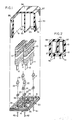
- the figures show an electrolytic capacitor assembly wherein a pair of capacitor sections 10 are housed in isolation from one another in a substantially cube-like rectangular parallelepiped case having a cover 50 and a base 30.
- Each capacitor section 10 is tab-wound and flattened in a usual manner with an electrode tab 11 connected to an anode foil and electrode tab 12 attached to a cathode foil during winding.
- Interleaved spacer material 15 preferably of paper, separates the foil electrodes which are preferably aluminum foil.
- Conductive means 21 and 22 are attached to tabs 11 and 12, respectively. These conductive means are assembled with gaskets 23 and are attached to base 30 through holes 31, 32, 33 and 34. Securing is attained by upsetting the long shank end of means 21 and 22 by conventional techniques. Conductive members 41 and 42 are attached to means 21 and 22, respectively, also by conventional techniques.
- Holes 31 through 34 are dissimilarly spaced apart in base 30 so that when members 41 and 42 are attached, or other mounting means are used, there is only one way of mounting the assembly on a printed circuit board.
- Base 30 has molded into it a longitudinal groove or channel 35 to receive portion 55 of internal wall 53 of cover 50 as described below.
- Cover 50 has an internal vertical wall 53 extending from back wall 52 to the front wall (cut away). Wall 53 is parallel to side walls 51 and separates the interior of cover 50 into two isolated compartments.
- the bottom edge of wall 53 is notched adjacent to bottom edge of the back wall 52 as indicated at 54 and also correspondingly at the front.
- the notched portions rest on the edge of base 30 and portion 55 of wall 53 is received by channel 35 of base 30 so that when the assembly is sealed each capacitor section 10 is isolated from the other.
- Cover 50 and base 30 are preferably made of Ryton, a polyphenylene sulfide polymer, and are preferably sealed by ultrasonic welding as taught in the prior art by both Clement and Efford et al noted above.
- Cover 50 bears vent mechanisms 57 and 58 for each of the two chambers enclosing capacitor sections 10 in the preferred embodiment.
- Each vent lies on the exterior junction of a side wall 51 and top surface 56 of cover 50. Vents 57 and 58 each extend parallel to interior wall 53, but on the exterior surface of cover 50.
- Each vent is a beveled portion formed by eliminating material from the right-angle junction of the two perpendicular surfaces. The elimination of material this cover 50 thickness to 0.037 (0.94 mm) along the bevel vents 57 and 58. This thickness will withstand an internal pressure of 75 psi before venting.
- the beveled vents are preferably provided in the cover during the molding of the cover. Utilization of a mold having the bevel formed therein permits the attainment of extremely reproducible vent thicknesses in a production-scale run of covers.
- the bevels may also be formed by grinding or slicing away corner material after the case is sealed; however stresses may be formed in the cover, and uniformity suffers in comparison to molding the vent in place.
- the capacitor sections 10 may be impregnated with electrolyte (not shown) before sealing the unit or after sealing through holes in the base which are then filled with plastic.
Landscapes
- Engineering & Computer Science (AREA)
- Power Engineering (AREA)
- Microelectronics & Electronic Packaging (AREA)
- Fixed Capacitors And Capacitor Manufacturing Machines (AREA)
Applications Claiming Priority (2)
| Application Number | Priority Date | Filing Date | Title |
|---|---|---|---|
| US07/145,440 US4803598A (en) | 1988-01-19 | 1988-01-19 | Electrolytic capacitor assembly |
| US145440 | 1988-01-19 |
Publications (3)
| Publication Number | Publication Date |
|---|---|
| EP0325039A2 true EP0325039A2 (de) | 1989-07-26 |
| EP0325039A3 EP0325039A3 (en) | 1990-01-03 |
| EP0325039B1 EP0325039B1 (de) | 1992-06-03 |
Family
ID=22513124
Family Applications (1)
| Application Number | Title | Priority Date | Filing Date |
|---|---|---|---|
| EP88311658A Expired EP0325039B1 (de) | 1988-01-19 | 1988-12-09 | Zusammenbau von elektrolytischen Kondensatoren |
Country Status (3)
| Country | Link |
|---|---|
| US (1) | US4803598A (de) |
| EP (1) | EP0325039B1 (de) |
| DE (1) | DE3871763T2 (de) |
Cited By (1)
| Publication number | Priority date | Publication date | Assignee | Title |
|---|---|---|---|---|
| WO2012110181A1 (de) * | 2011-02-15 | 2012-08-23 | Sew-Eurodrive Gmbh & Co. Kg | Anordnung mit einem gehäuse |
Families Citing this family (7)
| Publication number | Priority date | Publication date | Assignee | Title |
|---|---|---|---|---|
| EP0447165A3 (en) * | 1990-03-12 | 1992-08-05 | Matsushita Electric Industrial Co., Ltd | Solid electrolytic capacitors and method for manufacturing the same |
| WO1998000849A1 (en) * | 1996-07-01 | 1998-01-08 | Aerovox, Inc. | Capacitor for mounting to an electric motor |
| US6249422B1 (en) * | 2000-02-01 | 2001-06-19 | Real Power Cap Company | Capacitor module for car audio system |
| US7365959B1 (en) | 2004-08-12 | 2008-04-29 | Charles Barry Ward | Multi value capacitor |
| US8188786B2 (en) | 2009-09-24 | 2012-05-29 | International Business Machines Corporation | Modularized three-dimensional capacitor array |
| US12057275B2 (en) * | 2022-11-22 | 2024-08-06 | Yu-Peng Chung | Packaging of roll-type solid electrolytic capacitor elements |
| TWI863473B (zh) * | 2023-08-01 | 2024-11-21 | 信容科技股份有限公司 | 具有內置式引線的小型化電容器 |
Family Cites Families (16)
| Publication number | Priority date | Publication date | Assignee | Title |
|---|---|---|---|---|
| US789877A (en) * | 1903-05-22 | 1905-05-16 | Vesta Storage Battery Company | Relief-valve for storage batteries. |
| US3277350A (en) * | 1962-11-16 | 1966-10-04 | Mallory & Co Inc P R | Wet electrolytic encapsulated capacitor |
| US3261902A (en) * | 1964-09-08 | 1966-07-19 | Mallory & Co Inc P R | Method of making encapsulated capacitor |
| US3439234A (en) * | 1966-12-05 | 1969-04-15 | Mallory & Co Inc P R | Self-venting housing for capacitors |
| US4045862A (en) * | 1973-01-10 | 1977-09-06 | P. R. Mallory & Co., Inc. | Electronic component and method |
| US3838316A (en) * | 1973-10-09 | 1974-09-24 | Western Electric Co | Encapsulated electrical component assembly and method of fabrication |
| GB1445807A (en) * | 1974-03-27 | 1976-08-11 | Erie Electronics Ltd | Electrical capacitors |
| US4104704A (en) * | 1974-12-23 | 1978-08-01 | P.R. Mallory & Co. Inc. | Capacitor including an electroplated layer thereover |
| US4017773A (en) * | 1975-05-27 | 1977-04-12 | Sprague Electric Company | Solid valve-metal capacitor with buried graphite in the particles in the electrolyte |
| GB1513348A (en) * | 1976-09-20 | 1978-06-07 | Matsushita Electric Industrial Co Ltd | Electrolytic capacitor |
| US4061224A (en) * | 1976-09-30 | 1977-12-06 | Fuhri William F | Carrying case for art supplies |
| EP0051272A3 (de) * | 1980-11-03 | 1984-03-28 | Rudolf Klaschka | Kondensatorbechergehäuse, Verfahren zu seiner Herstellung und Vorrichtung zu seiner Herstellung |
| US4326237A (en) * | 1981-01-02 | 1982-04-20 | Sprague Electric Company | Dual AC motor-run capacitors |
| US4447852A (en) * | 1982-06-14 | 1984-05-08 | Sprague Electric Company | Capacitor assembly |
| JPS5963718A (ja) * | 1982-10-04 | 1984-04-11 | 松下電器産業株式会社 | 密閉型電解コンデンサの防爆ケ−ス |
| US4547829A (en) * | 1984-05-30 | 1985-10-15 | Sprague Electric Company | Capacitor assembly |
-
1988
- 1988-01-19 US US07/145,440 patent/US4803598A/en not_active Expired - Lifetime
- 1988-12-09 DE DE8888311658T patent/DE3871763T2/de not_active Expired - Lifetime
- 1988-12-09 EP EP88311658A patent/EP0325039B1/de not_active Expired
Cited By (1)
| Publication number | Priority date | Publication date | Assignee | Title |
|---|---|---|---|---|
| WO2012110181A1 (de) * | 2011-02-15 | 2012-08-23 | Sew-Eurodrive Gmbh & Co. Kg | Anordnung mit einem gehäuse |
Also Published As
| Publication number | Publication date |
|---|---|
| DE3871763D1 (de) | 1992-07-09 |
| EP0325039A3 (en) | 1990-01-03 |
| US4803598A (en) | 1989-02-07 |
| EP0325039B1 (de) | 1992-06-03 |
| DE3871763T2 (de) | 1992-12-10 |
Similar Documents
| Publication | Publication Date | Title |
|---|---|---|
| US4385342A (en) | Flat electrolytic capacitor | |
| US3555370A (en) | Electrolytic capacitors having improved seal and vent | |
| EP0439686A2 (de) | Elektrischer Doppelschichtkondensator und Verfahren zu seiner Herstellung | |
| US4803598A (en) | Electrolytic capacitor assembly | |
| JPS6345749Y2 (de) | ||
| CN115360019A (zh) | 一种固态铝电解电容器及其制备方法 | |
| EP0458411A1 (de) | Dichtung für elektrolytischen Wickelkondensator | |
| CN215815608U (zh) | 一种电容器芯包及铝电解电容器 | |
| CN205723163U (zh) | 一种薄膜电容器 | |
| JPS6350840Y2 (de) | ||
| JPH0319214Y2 (de) | ||
| JPS6017904Y2 (ja) | 偏平角形電解コンデンサ | |
| US3553537A (en) | Electric component for use with printed wiring | |
| US20230344065A1 (en) | Battery and electronic device using same | |
| CN210722779U (zh) | 一种防止芯包晃动的铝电解电容器 | |
| JPS5915491Y2 (ja) | 端子同一方向形電解コンデンサ | |
| CN218038863U (zh) | 一种防爆型电容器 | |
| JPS59123220A (ja) | 積層形電解コンデンサおよびその製造方法 | |
| CN212659440U (zh) | 应用于美容仪的迷你型电容器 | |
| CN215868980U (zh) | 分补电容器 | |
| JP2606297B2 (ja) | 電子部品 | |
| KR970005070Y1 (ko) | 전기 이중층 콘덴서 | |
| JPS6161692B2 (de) | ||
| JPS5938047Y2 (ja) | 電解コンデンサ | |
| JPH10144576A (ja) | 電気二重層コンデンサバンク |
Legal Events
| Date | Code | Title | Description |
|---|---|---|---|
| PUAI | Public reference made under article 153(3) epc to a published international application that has entered the european phase |
Free format text: ORIGINAL CODE: 0009012 |
|
| AK | Designated contracting states |
Kind code of ref document: A2 Designated state(s): DE FR GB NL |
|
| PUAL | Search report despatched |
Free format text: ORIGINAL CODE: 0009013 |
|
| AK | Designated contracting states |
Kind code of ref document: A3 Designated state(s): DE FR GB NL |
|
| 17P | Request for examination filed |
Effective date: 19900208 |
|
| 17Q | First examination report despatched |
Effective date: 19910816 |
|
| GRAA | (expected) grant |
Free format text: ORIGINAL CODE: 0009210 |
|
| AK | Designated contracting states |
Kind code of ref document: B1 Designated state(s): DE FR GB NL |
|
| REF | Corresponds to: |
Ref document number: 3871763 Country of ref document: DE Date of ref document: 19920709 |
|
| ET | Fr: translation filed | ||
| PLBE | No opposition filed within time limit |
Free format text: ORIGINAL CODE: 0009261 |
|
| STAA | Information on the status of an ep patent application or granted ep patent |
Free format text: STATUS: NO OPPOSITION FILED WITHIN TIME LIMIT |
|
| 26N | No opposition filed | ||
| REG | Reference to a national code |
Ref country code: GB Ref legal event code: IF02 |
|
| PGFP | Annual fee paid to national office [announced via postgrant information from national office to epo] |
Ref country code: GB Payment date: 20031203 Year of fee payment: 16 |
|
| PGFP | Annual fee paid to national office [announced via postgrant information from national office to epo] |
Ref country code: NL Payment date: 20031205 Year of fee payment: 16 |
|
| PGFP | Annual fee paid to national office [announced via postgrant information from national office to epo] |
Ref country code: FR Payment date: 20031210 Year of fee payment: 16 |
|
| PGFP | Annual fee paid to national office [announced via postgrant information from national office to epo] |
Ref country code: DE Payment date: 20031218 Year of fee payment: 16 |
|
| PG25 | Lapsed in a contracting state [announced via postgrant information from national office to epo] |
Ref country code: GB Free format text: LAPSE BECAUSE OF NON-PAYMENT OF DUE FEES Effective date: 20041209 |
|
| PG25 | Lapsed in a contracting state [announced via postgrant information from national office to epo] |
Ref country code: NL Free format text: LAPSE BECAUSE OF NON-PAYMENT OF DUE FEES Effective date: 20050701 Ref country code: DE Free format text: LAPSE BECAUSE OF NON-PAYMENT OF DUE FEES Effective date: 20050701 |
|
| GBPC | Gb: european patent ceased through non-payment of renewal fee |
Effective date: 20041209 |
|
| PG25 | Lapsed in a contracting state [announced via postgrant information from national office to epo] |
Ref country code: FR Free format text: LAPSE BECAUSE OF NON-PAYMENT OF DUE FEES Effective date: 20050831 |
|
| NLV4 | Nl: lapsed or anulled due to non-payment of the annual fee |
Effective date: 20050701 |
|
| REG | Reference to a national code |
Ref country code: FR Ref legal event code: ST |