EP0323558B1 - Verfahren zum Füllen von Polygonen - Google Patents
Verfahren zum Füllen von Polygonen Download PDFInfo
- Publication number
- EP0323558B1 EP0323558B1 EP88119280A EP88119280A EP0323558B1 EP 0323558 B1 EP0323558 B1 EP 0323558B1 EP 88119280 A EP88119280 A EP 88119280A EP 88119280 A EP88119280 A EP 88119280A EP 0323558 B1 EP0323558 B1 EP 0323558B1
- Authority
- EP
- European Patent Office
- Prior art keywords
- polygon
- scan line
- line
- routine
- octant
- Prior art date
- Legal status (The legal status is an assumption and is not a legal conclusion. Google has not performed a legal analysis and makes no representation as to the accuracy of the status listed.)
- Expired - Lifetime
Links
Images


Classifications
-
- G—PHYSICS
- G06—COMPUTING; CALCULATING OR COUNTING
- G06T—IMAGE DATA PROCESSING OR GENERATION, IN GENERAL
- G06T11/00—2D [Two Dimensional] image generation
- G06T11/40—Filling a planar surface by adding surface attributes, e.g. colour or texture
Definitions
- This invention relates to polygon filling, that is to say, in data processing output devices such as graphical raster displays, to a method for filling in the area defined by the boundaries of a polygon that is being displayed.
- a general routine for filling polygons As described in J. D. Foley and A. Van Dam, Fundamentals of Interactive Computer Graphics (Addison-Wesley, 1982), pages 456-460.
- This general routine is referred to as an edge table driven routine.
- This type of routine is used in computer graphic applications as one of the standard routines that are called to perform certain graphic tasks. Some of these graphic tasks include drawing lines, circles, arcs, etc., including filling polygons. These tasks are typically supplied in a library containing graphical functions such as a Graphics Support Library (GSL).
- GSL Graphics Support Library
- a graphics support library is a package of graphic subroutines that are typically delivered with a processing system so that users can write to displays with a higher level interface without having to know the complexity of any particular display and how to write to that display.
- this routine becomes too time consuming.
- a routine becomes unduly time consuming when users of graphical applications have to wait after they have selected the polygon fill routine from a graphics library before the display screen displays the resulting filled polygon. It is important for customer satisfaction that the fill rate be as fast as possible without trading off the accuracy of the filled polygon.
- the routine routine uses the Bresenham routine defined in J. E. Bresenham, "Algorithm for Computer Control of a Digital Plotter", IBM Systems Journal , Vol. 4, No. 1 (1965), pages 25-30.
- the Bresenham routine is also described in J. D. Foley and A. Van Dam, Fundamentals of Interactive Computer Graphics (Addison-Wesley), 1982), pages 433-436.
- the Bresenham routine is used to scan the lines of the polygon boundary, and to generate the points that make up the polygon boundary.
- this known polygon fill routine selects the first point after a change in the scan line. The problem with this routine is that it does not accurately fill within the boundaries of the polygon. The resulting displayed polygon will appear as if it is incompletely filled. That is, the fill does not reach the boundary of the polygon at all locations.
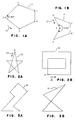
- a polygon 10 is convex if all of its interior angles at the vertices A, B, C, D, E, are less than 180 degrees.
- Fig. 1B illustrates a polygon 11 that is not convex by this definition since it has an interior angle at its vertex E which is greater than 180 degrees.
- a method is disclosed in the article that determines whether or not all interior angles are less than 180 degrees, and therefore whether or not the polygon is convex.
- the method takes the cross product for each two adjoining vectors given by the edges of the polygon. If all of the cross products have the same sign, then the polygon is convex.
- the cross product indicates whether each side of the polygon is turning in the same direction. As shown in Fig. 1A, proceeding around the polygon 10 in the direction shown by the arrow 12 and starting at vertex E, all turns are to the left. However, in Fig. 1B, proceeding around the polygon 11 in the directions shown by the arrow 13 and starting at vertex D, all turns are to the left, except the turn at vertex E which is to the right.
- the present invention provides a method of polygon filling in a by-line, pel driven data processing output in which a polygon to be filled is defined by a multiple line boundary which can be defined by a plurality of selectable pels per scan line, in which a general polygon fill routine is used unless a once round test performed on the vertices of the polygon, defined by the sign of the difference between ordinates transverse to the scan line direction of successive vertices of the polygon changing sign exactly two or three times in one circuit of the polygon, is satisfied, in which case a faster fill routine is used, possibly with other tests having to be additionally satisfied.
- An embodiment of the invention disclosed hereinafter implements one of three polygon fill routines for optimising the processing time required to fill a polygon depending upon the particular shape of the polygon. Several tests are used on the polygon to determine if the polygon falls within the class of polygons to be filled by a particular polygon fill routine.
- the processing time required for filling a polygon is optimised by a first polygon fill routine by storing one maximum value for each scan line of the polygon for one half of the polygon, and one minimum value for each scan line of the polygon for the other half of the polygon.
- This routine stores exactly one value since the routine knows whether at any particularly point along the polygon, the point is part of the maximum or minimum values.
- the first polygon fill routine is inadequate to accurately fill a polygon within this class of polygons.
- the processing time required to accurately fill a polygon is optimised by storing two minimum and maximum values for each scan line of a polygon. The fill line is then drawn from the least minimum value to the greatest maximum value for each scan line.
- the first polygon fill routine fills polygons that are strictly convex.
- the second polygon fill routine fills a larger set of polygons than the first polygon fill routine.
- the second polygon fill routine fills all polygons which can be filled with exactly one continuous line per scan. Polygons in this set may have x-concavity and crossing lines.
- the first polygon fill routine checks the polygon to determine if the polygon is strictly convex by checking for the combination of two conditions. First, the polygon is checked for consistent "turning" direction. That is, determining whether each sequential line of the polygon bend in the same direction. As a result of this test, the direction is determined as being clockwise or counter clockwise. For any two adjacent lines with points (x0, y0), (x1,y1), (x2,y2), the calculation for the sign of the vector product is as follows: (y1-y0)*(x2-x1)-(y2-y1)*(x1-x0) If the above expression is greater than zero, then the polygon is turning right, or clockwise. If the above expression is less than zero, then the polygon is turning left, or counter clockwise. If all adjacent lines have the same vector product sign, the polygon meets this first condition as having a consistent "turning" direction.
- the second condition that must be met for the polygon to be strictly convex is the once around y direction test. This is equivalent to having the sum of the interior angles equal to 360 degrees.
- the once around condition is met if by starting at the first line of the polygon the algebraic sign of y(i+1)-y(i) for all adjacent vertices changes exactly 2 or 3 times. Horizontal lines are considered to have the same sign as the previous line. Polygons passing this test have y-convexity. That is, for any value of y there is one and only one continuous fill line. While traversing around the points of the polygon for the "once around" test, the maximum and minimum y values and locations are stored in memory.
- the polygon is strictly convex.
- the lines of the polygon can be partitioned into two sets such that the lines of one set defines maximum values of scan lines, while the other set defines minimum values.
- a single table of two values per y value is used.
- the y value ranges from zero to the largest number of scan lines on the display of interest. Starting at the point of the minimum y value and proceeding in a counter clockwise direction, for each line of the polygon the maximum value of that line for every scan line that it intersects is saved in a table. An exception is made for vertexes having two lines that intersect on the same scan line. Special processing is used to store one maximum value on that scan line of a pel that both lines may share. This is continued for each line of the polygon until the maximum vertex in the y direction (ymax) is reached. From this point on, the lines define only minimum scan lines.
- the minimum value of that line for every scan line that it intersects is saved in the table. Again, an exception is made for vertexes having two lines that intersect on the same scan line. Special processing is used to store one minimum value on that scan line of a pel that both lines may share.
- the GSL multiline draw routine is called in one preferred embodiment to draw one horizontal line per y in the range ymin to ymax. Other preferred embodiments may use other methods to draw a line from the selected minimum pel to the selected maximum pel for each scan line.
- the second polygon fill routine fills a larger set of polygons than the first polygon fill routine.
- All polygons can be filled with this second polygon fill routine if the polygon can be filled with exactly one continuous line per scan line. Polygons in this set have x-concavity and/or crossing lines.
- the lines of the polygon are again divided into two sets, those between ymin and ymax in the order originally presented. Lines of the polygon in either set may define a minimum or maximum on a given scan line. Therefore, two tables are used to store either the minimum or the maximum value, one for each set of lines.
- both the minimum and maximum of a given line at the intersection with a scan line are stored.
- the second table likewise stores the minimum and maximum values of a given line at each intersection with a scan line for the second set of lines in the polygon.
- the minimum value for a given scan line is the minimum of the two values for that scan line from the two tables.
- the maximum value for a given scan line is the maximum of the two values for that scan line from the two tables.
- the first stage scans all the lines of the polygon. For each line of the polygon, the Bresenham routine is utilised on each point along a line of the polygon.
- the processing time required to fill a polygon is optimised since the determination of whether the value of a point is to be stored in a min/max table is made at the time the Bresenham routine operates on that particular point.
- the second stage the post processing is done integrally with the preprocessing, the first stage. Once the first stage, the preprocessing is complete, only a minimal amount of additional processing is needed to fill the polygon.
- the second stage, the post process, is virtually nonexistent for the first polygon fill routine.
- a single store is performed in a table having a minimum and maximum value for each y value of each scan line.
- the polygon is filled by scanning the array from ymin to ymax, and drawing a line from the minimum to the maximum value stored for each y value.
- the polygon is filled by first determining the maximum of the maximum values stored, and the minimum of the minimum values stored for each y value. A line is then drawn from the least minimum value to the greatest maximum value for each y scan line.
- the embodiment of the present invention disclosed herein comprises a suite of two routines for faster polygon filling, together with a slower known general routine and the necessary driver for the combination.
- These routines could be used with any by line, pel driven output, such as the displays 94 (Fig. 4A) provided with a processing system 90 such as the IBM RT PC.
- Fig. 4B shows the logical structure 91 of the processing system 90.
- Fig. 4C shows the physical structure 92 of the processing system 90.
- the RT PC is more fully described in IBM RT Personal Computer Technology , Form No. SA23-1057.
- Each routine has advantages and disadvantages. Depending on the relative processor, display adapter, memory, and I/O speeds, one or the other routines will be more efficient for a particular implementation for a given display.
- Both fast fill routines are used to fast fill certain polygons having a specific classification of shape.
- the first fast polygon fill routine utilises one table 100 (Fig. 5) for storing values 110 at each y location 101
- the second fast polygon fill routine utilises two tables 111, 112 (Fig. 6) for storing values 113 at each y location 101 that are needed to fill a polygon.
- the size of the table 100 (Fig. 5), 111, 112 (Fig. 6) that is required depends upon the size of the particular display screen 94 (Fig. 4A) that is being used. If the display 94 that is being used is a monochrome display having 375 picture elements (pels) in the y direction 102, the table 100, 111, 112 needs 375 entries 103. If the display 94 (Fig. 4A) is an APA8 display which has 512 pels in the y direction 102, then the table 100, 111, 112 needs 512 entries 103. If the display 94 (Fig. 4A) is a megapel display which has 1024 pels in the y direction 102, the table 100, 111, 112 needs 1024 entries 102. The y entries 101 in the table 100, 111, 112 would range from zero 105 to the size of the screen minus one 107. The table 100, 111, 112 is therefore sized according to the size of the display 94.
- the second fast fill routine utilises two tables 111, 112 shown in Fig. 6. Each table, 111, 112 has a minimum column 116 and maximum column 118. The tables 111, 112 also have a size that range from zero 105 to the size of the screen minus one 107.
- the lines 121 - 124 of polygon 120 are represented by picture elements (pels) such as pels 130 that are turned on throughout scan lines 132 y10 - y18 to represent the line 121 of polygon 120.
- the lines 121 - 124 of polygon 120 are not actually displayed on the screen 94 (Fig. 4A), but are shown here for purposes of description only. Determining which pels 130 are to be turned on for each scan line 132 to best represent each of the lines 121 - 124 when displayed is accomplished by utilising the Bresenham routine as described in J. E.
- the points 130 of a polygon 120 are generated by using the Bresenham routine.
- the pels 130 selected by the Bresenham routine to represent the line 121 are shown in Fig. 7 as filled in zero's.
- the pels 131 not selected by the Bresenham routine to represent a line 121 of the polygon 120 are shown in Fig. 7 as x's.
- the two fast fill routines each have a different range of a set of polygons 33 (Fig. 8A), 34 (Fig. 8B), 35 (Fig. 8C) that can be filled with the particular routine.
- the second routine can fill a larger set of polygons 33, 34, 35 than the first routine 60.
- This set includes the set of all polygons that can be filled such that for each y value 102 there is a unique single line 133 that can be used to fill the polygon 33, 34, 35.
- This set of polygons 33, 34, 35 can include polygons that are concave 28 in the x direction 104. Additionally, this set includes polygons 35 having crossing lines 37, 38.
- Polygon 36 (Fig. 8A), 34 (Fig. 8B), 35 (Fig. 8C) that can be filled with the particular routine.
- the second routine can fill a larger set of polygons 33, 34, 35 than the first routine 60.
- This set includes the set of all polygons that can be filled such that for each
- 8D illustrates that for each y value 102, there is not a unique single line that can be used to fill the polygon 36. For the lower values of y, there are two lines 134, 135 for each value of y. Therefore, a polygon 36 that is concave 29 in the y direction can not be filled using the second fast fill routine.
- the set of polygons includes only strictly convex polygons 33. There can not be any concavity in either x or y direction, and no crossing lines.
- each fast fill routine determines whether the polygon fits within the range of polygons for that particular routine and exits from the routine as quickly as possible when no fit is discovered. This is why, although one of the tests is common to both routines, it appears in both front ends. The following describes the tests that are performed on the polygon to determine in which range of polygons a particular polygon belongs.
- the following discussion will centre around the polygon 120 in Fig. 7. To begin, a discussion as to the definition of the term direction sensitivity of a polygon is needed.
- the same polygon 120 can be described by a sequence of x and y coordinates in either a clockwise 25 or counter clockwise 26 order around the polygon 120.
- the application of any given polygon fill routine should have the same result whether the polygon fill routine was applied to the polygon in a clockwise 25 or counterclockwise 26 direction. That is, the polygon should result in the same fill regardless of the direction the polygon 120 was traversed in applying the fill routine. In both fast fill routines hereof, there is no direction sensitivity regardless of the order that the coordinates of the resulting Bresenham pels 130 are presented.
- the first test for the first fast fill routine for strictly convex polygons determines the direction, clockwise 25 or counterclockwise 26, that the polygon is traversed in presenting the coordinates of the corresponding pels 130 of the polygon 120.
- the first fast fill routine is not direction sensitive since the direction is specifically detected as part of the test of the routine. If the direction is found to be clockwise 25, the order that the points (pels) 130 are scanned is reversed. The points 130 are always scanned counterclockwise 26 around a polygon.
- each table 111, 112 has minimum 116 and maximum 118 values in the x direction 104 for each scan line 132 in the y direction 102. Therefore, it does not matter if the polygon 120 is traversed up one side 114 and down the other 115 or vice versa. The result is two tables 111, 112 with minimum 116 and maximum 118 values in each table 111, 112 for each scan line 132 in the y direction 102.
- the maximum value of the two maximum values 118 for the two tables 111, 112 is selected, and the minimum value of the two minimum values 116 for the two tables 111, 112 is selected.
- a fill line is then drawn from the selected minimum pel to the selected maximum pel.
- a fill line 142 is then drawn from pel 54 to pel 46 by turning on all the pels 130, 131 there between as indicated by the symbolic boxing of the pel mark at each pel location.
- the first fast fill routine there is a determination as to whether the polygon 120 fits into the range of polygons for this particular fill routine and, at the same time, on the assumption that the determination will succeed, certain initialisation values are registered.
- this effectively extended test There are three parts to this effectively extended test which are included within the front end of the routine: - the clockwise/counterclockwise test, picking up the turning direction as an aside; the once around test in either the x or y direction and the determination of y minimum and y maximum for the particular polygon for table initialisation. If the polygon meets the first two of these tests, the operative part of this first fast fill routine called "genline" will be called from the gsff routine. If the polygon fails either one of these tests, there will be an escape out, to the general fill routine as described in J. D. Foley, A. Van Dam, Fundamentals of Interactive Computer Graphics , pages 456-460.
- the first test for the first fast fill routine is the clockwise/counterclockwise test, otherwise referred to as the turning test and is described in "Method To Determine the Convexity of Polygons", IBM Technical Disclosure Bulletin , Vol. 28, No. 5, October 1985.
- the preferred embodiment of this invention incorporates this turning test to check for consistent turning direction. That is, going from line to line of a polygon, it is determined whether each new line bends in the same direction. As a fallout of this test, clockwise or counterclockwise is also determined. If two adjacent lines 121, 122 (Fig. 7) has points (x0,y0), (x1,y1), (x2,y2), the calculation for the sign of the vector product is as follows: (y1-y0)*(x2-x1)-(y2-y1)*(x1-x0) If the above expression is greater than zero, then the polygon 120 is turning right for those two lines of the polygon.
- the vector product of lines 121 and 122 of polygon 120 would be less than zero indicating that the polygon 120 is turning left or counterclockwise 26. This turning test is repeated for each two adjacent lines of the polygon. If the results of this test for the same polygon result in the same sign, the polygon meets the consistent turning direction test.
- the second condition that must be met for the polygon to be strictly convex is the once around y direction test. This is equivalent to having the sum of the interior angles equal to 360 degrees.
- the "once around" test states that if the starting location for traversing the polygon begins at the lowermost vertex 1 (Fig. 7), and the polygon is traversed sequentially along its edges 121, 122, 123, 124, the y coordinates 102 of the sequential edges 121, 122, 123, 124 must first all increase and then decrease. In other words, a first group of edges 121, 122 of the polygon 120 must first all rise, and the second group of edges 123, 124 of the polygon 120 must all then fall.
- the once around condition is met if by starting at the first line 121 of the polygon 120, not necessarily the lowest point thereof, the algebraic sign of y(i+1)-y(i) for all adjacent vertexes changes exactly 2 or 3 times.
- the consistent turning direction test along with the once around in the y direction test which is equivalent to stating that the sum of the angles inside the polygon is 360 degrees, state that the polygon 120 has strict convexity.
- the sign of the vector product calculated in the consistent turning direction test is then used to determine the direction of the polygon 120. If the value of the above expression is greater than zero, then the polygon 120 was traversed in a clockwise direction 25. If the value of the above expression is less than zero, then the polygon 120 was traversed in a counterclockwise direction 26. Since the first fast fill routine is based on a unidirectional, say counterclockwise 26, operation, if the sign of the expression indicates a clockwise direction 25 of presentation, the order that the points 130 are traversed is reversed.
- the lines 121, 122, 123, 124 of the polygon 120 can be partitioned into two sets 114, 115 such that the lines 121, 122 of one set 114 defines maximum values 107 (Fig. 5) of scan lines 132, while the other set 123, 124 defines minimum values 106 (Fig. 56). Regardless of the presentation of the polygon 120 through the preprocessing of the polygon in the above tests, vertex 1 will be determined to be y minimum, and vertex 2 will be determined to be y maximum.
- the maximum value of a scan line 132 is stored in the max entry 107 (Fig. 5) of the table 100 for the appropriate index 103 of y.
- the maximum value 107 of x at the previous scan line is stored. This is repeated for each scan line 132 of y until y maximum 2 is reached.
- the polygon 120 is traversed down from y maximum 2 to y minimum 1 down the lines 123, 124 that were previously partitioned. For this set 115 of partitioned lines 123, 124, the last point 130 on the scan line 132 is stored as the minimum value 106 of x in the table 100 for each y entry 103. This is repeated for each y scan line 132.
- the routine begins at y minimum (pel 1, Fig. 7) and proceeds in a counterclockwise direction 26 to y maximum shown as pel 2.
- table 100 having min and max entries 110 for each y 102 is used.
- the maximum x value (which is the last point (pel) 130 on a scan line 132) for each y 102 is stored in the table 100.
- y maximum 2 is reached in the traverse, the polygon is traversed from y maximum 2 to y minimum 1.
- the minimum value for a pel 130 on each scan line 132 is stored in the table.
- the minimum value for a pel 130 at a scan line 132 would be stored in the minimum entry 106 for the corresponding y entry 103.
- the xs argument is a pointer to the beginning of the array 100 which contains both min 106 and max 107 values in an alternating fashion as shown in Fig. 5.
- the ys argument 155 is simply an array of points 0,0,1,1,2,2,3,3, etc. to the size of the screen minus one, i.e., 1023, 1023.
- the ys array 101 is initialised once. When this array 101 is called, it is called with an x 110 and y 101 pair to get the right y value with the right x value.
- the routine continues by initialising the once around y test and the turning test including the y min and y max at the first point.
- the for loop keeps calculating the turning test, it progressively updates y min and y max and it updates the once around test.
- the sign of the inner product changes a local flag is set.
- the new sign is equal to 0 if it is negative, and 1 if it is positive.
- One is added to the count if the new sign is not equal to the old sign. This counts the number of changes in the sign.
- the local flag which indicates that the direction calculated in previous incidences of the loop is different from the direction that was just calculated, or if the count of the number of changes in the sign of y reaches four - or, in theory, greater than four - the test fails, a combined fail flag is set and the loop is exited. If the combined fail flag is not set, the loop continues.
- the next step is the y high test. If the new y is higher than the previous y max, the y max is updated to the new value. The index where the new y max was found is stored. The same is done with the minimum. If the maximum was not exceeded, the y min value is checked to see if the new y value is less than the previous y min value. If it is, the y min value is updated with the new y min value. The index is also updated to note the location of the y min value. This ends the loop which can be regarded as a pretest.
- the total number of points for the y array 101 (Fig. 5) is calculated as two times the sum of y max minus y min plus one.
- the direction determined to be constant in the pretest is zero, then it is already counterclockwise, and the points 130 are scanned from the low point in a counter clockwise direction for each line 121-124, in the polygon. If the low point is not the first line of the polygon, the parameters for genline, the actual call, to the heart of the first fast fill routine, are adjusted to accommodate this. The steps prior to genline call ensured that the right line was pointed to and that it was counter clockwise, etc.
- Genline has five arguments corresponding to the parameters, possibly adjusted, as described above.
- the first argument is an address to the min/max array 100 (Fig. 5) in which values of xmin 106 and xmax 107 for each y value 103 are stored.
- the next two arguments are the x and y of the jth point in the scan and the last two arguments are the x and y of the point immediately after the jth point. Therefore, genline is called with a pointer into the array 100, and a line described by an x and y for a first pel and the next adjacent x and y for the second pel.
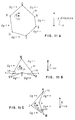
- Genline computes the minimum 106 and maximum 107 values for each y value of a scan line 132. It is assumed that the polygon 120 is strictly convex and the polygon 120 is presented in a counterclockwise 26 order. Therefore, the polygon 120 can be filled with a single horizontal line 142 for each value of y 102. Only one table 100 is used, and only one minimum 106 and maximum 107 value is saved in this table 100 for each scan line 132. A line with multiple pels 130 at the same y 102 is handled by only updating x when y changes. For lines in octants I, II, VII, VIII the update will be maximum 107, while for octants III, IV, V, VI the update will be minimum 106. As shown in Fig.
- the octant I begins at 0 degrees where y is zero and x is any positive value and terminates at 45 degrees.
- Octant II ranges from 45 degrees to 90 degrees. This continues in likewise fashion for octants I-VIII.
- a line of a polygon is in octant I if the line's angle is between zero and 45 degrees.
- a line of a polygon is in octant II if the angle of the line is between 45 degrees and 90 degrees.
- a line of a polygon is in one of the eight octants depending on the angle of the line.
- the polygon 120 is organised within these octants such that as the polygon is traversed up the front face 121, 122, the points can only lie in octants VII, VIII, I, II.
- the table 100 (Fig. 5) is specifically designed for the first fast fill routine, but could be used for other implementations.
- the key is that since there is only one x minimum 106 and one x maximum 107 for each y 103, all y's are constant and are computed only once at initialisation.
- the table is organised as illustrated in Fig. 5 as follows: y0 xmin y0 xmax y1 xmin y1 xmax y2 xmin y2 xmax . . . . ymax xmin ymax xmax
- the xmin is initialised for the ymax, and the xmax is initialised for the ymax. This eliminates having to save the x value, minimum or maximum, at the first point of a line.
- the first point 141, 161 (Fig. 7) is excluded when drawing a line, but every point 130 after that is included. Only the portion of the table 100 from ymin 1 to ymax 2 of the given polygon 120 is used for filling the polygon.
- genline generates the points 130 for one line 121 - 124 of the polygon 120.
- the slope of the line is generated and the address of the present location in the array is calculated.
- This address points to the minimum of x 106 in the table 100 at the present location. For example, if y were 10, the pointer would point to the 20th location 108 in the array 100. This entry 108 would contain the minimum x value 106 for y10, and the next entry 109 would contain the maximum value 107 of x for y10.
- the special case where the line of the polygon 120 is horizontal is covered as follows: If the first y is equal to the second y, then there is a horizontal line. If on the horizontal line, x2 is greater than x1, all the points are on the same scan line, and the implementation of the Bresenham routine is not needed. In this case the greatest value of x, x2, is stored as x max. If x2 is less than x1, the line lies in either octant III, IV, V, VI and the smallest value of x, x1, is stored as x min 106.
- the octant of each one of the lines of the polygon is determined and the lines of the polygon are traversed sequentially while conceptually stepping repetitively from a previous scan line to a next scan line during said sequential traverse. If the current line is in octant I, a last selectable pel on the previous scan line is selected after stepping from the previous scan line to the next scan line, and the last selectable pel on the next scan line is selected if the next scan line is a last scan line. If the line is in octant V, the last selectable pel on the previous scan line is selected after stepping from the previous scan line to the next scan line while the last selectable pel on the next scan line is selected if the next scan line is a last scan line.
- the selectable pel on said next scan line is selected. If the line is in octant IV or octant VIII, the first selectable pel on the next scan line is selected after stepping from the previous scan line to the next scan line.
- the "a” and “b” constants are used to generate three more Bresenham constants called "bma", "b2" and "i".
- the bma constant 170 is equal to two times b minus a.
- the b2 constant 171 is equal to two times b.
- the i constant 172 is the error constant which is equal to 2 times b minus a minus x2 less than x1.
- the term x2 less than x1 forces the rounding to be correct so that the same points are selected regardless of the direction the polygon is traversed. An example of this is shown in Fig. 10.
- a Bresenham line is drawn by traversing points in one direction, the same Bresenham line will not result if the points are traversed in the opposite direction.
- a simple way to show this is a line 8 that has a slope equal to one half as shown in Fig. 10. If the line starts at (0,0), pel 81 and ends at (2,1), pel 84, the ideal line 80 lies directly between pels 82 and 83.
- the Bresenham routine is defined such that there is a rounding up. Therefore, pel 83 would be turned on instead of pel 82 if the line were in the first octant.
- the Bresenham line would therefore consist of pels 81, 83, 84.
- the routine is looking to store the maximum value of x for each y.
- the first point 141, (Fig. 7) is excluded in the loop.
- the loop begins with x equal to x1 plus 1. This loop is performed for x less than or equal to x2. If the error coefficient is less than zero, this means that the value was not great enough to move to the next scan line.
- the constant b2 is added to i and the loop is done again. If i is equal or greater than zero, this means that the half way point is exceeded and the next scan line is accessed. In that case, the previous value (x minus 1) 42, 44, 46, etc. on the previous scan line is saved in the table as x max 107 for the previous value of y.
- All of the other cases also store the last pel from the previous scan line.
- the genline routine is called. The part of the routine that is implemented is dependent upon which octant the line resides.
- the routine only stores one pel location 130 for each scan line 132 for each line 121- 24 of the polygon 120. This minimises the number of store operations that have to be performed. Since the polygon is strictly convex, there will be exactly one minimum 106 and maximum 107 value stored for each scan line 132.
- the main driver program calls to the first fast fill routine, gsff which, in turn, if permitted, calls genline. If the gsff pretest fails, the break to the driver results in a call to the second fast fill routine, gsff2. If the pretest conditions of gsff2 are met, it calls its own genline, genline2.
- the second fast fill routine also checks to see if the particular polygon is within the range of polygons suitable for the second polygon fill routine. This test is simpler than the test for the first polygon fill routine since the test for the second polygon fill routine only contains the once around in the y direction test. As long as the y values 102 of a particular polygon only increase, and then decrease, assuming a start at the lowest point thereof, the polygon can be filled by this second fast fill routine.
- the polygon 62 shown in Fig. 11B shows four different changes in signs of delta y as the polygon 62 is traversed clockwise starting with vertex V.
- the polygon 62 shown in Fig. 11B illustrates a polygon that could not be filled with this second polygon fill routine 80.
- This polygon 62 could not be filled with just one scan line 134, 135 as illustrated between point 5 and point 6. Although both point 5 and point 6 have the same y value 102, two different lines 134, 135 are needed to fill the polygon 62.
- the second fast fill routine could be modified to fill polygons having the characteristics of the polygon 62 in Fig. 11B, but the routine would become more complex.
- the routine could be expanded by having two sets of minimum and maximums, and initialising these values. However, the routine becomes more complex and the generality of the routine is lost.
- the polygon 63 shown in Fig. 11C is not strictly convex, but this polygon 63 still fits in with the second polygon fill routine 80.
- This polygon 63 is concave in the x direction. However, this polygon 63 meets this once around test.
- the delta y is positive from vertex J to vertex K.
- the delta y sign is negative from vertex K to vertex L and vertex L to vertex M.
- the delta y sign is then positive from vertex M to vertex J. No matter what the starting position, there will either be two or three changes in the sign of delta y.
- This polygon can be filled by a unique y scan line 132 for each y value 102.
- Genline2 is similar to genline1. However, instead of storing the last point on the scan line 132, it stores the first and last points on a scan line 132. The slope is computed as in genline1. The same octant logic is followed as in genline1 and the Bresenham routine is initialised in the same way. The same for loop from x equal x plus one to x less than or equal to x2, or the counterpart y loop depending on the quadrant, is performed. The only difference is that now both minimum and maximum values are selected. If i is less than zero, this means that nothing is changing.
- Execution of genline2 begins at the point where y has the minimum value 1.
- y has the minimum value 1.
- the minimum and maximum value on each scan line 132 is saved in two tables 111, 112, Fig. 6.
- Each table 111, 112 has two entries 116, 118 for each y value 103.
- entries are made in a second table 112.
- entries are made in a first table 111.
- table B 112 Traversing up the polygon 120, table B 112 is used, and traversing down the polygon 120, table A 111 is used. There are more stores and processing in this routine than is required by the first fast fill routine. This makes the second fast fill routine slower than the first. However, the advantage is that it can fill a larger class of polygons Fig. 1A, 1B, 3A, 3B, 8A, 8B, 8C, 11A, 11B, 11C. However, it is still appreciably faster i.e, it takes less processing time, than the general polygon fill routine.
- the two tables 111, 112 are combined into one table.
- the combining consists of finding the minimum of two minimums and the maximum of two maximums for each scan line 132.
- the multiline routine could be written that takes a pointer to both tables 111, 112 and create the min and max for each scan line as it proceeds.
- both values of the first pel 41, 43, 45 and last pels 42, 44, 46 on each scan line 132 respectively are stored.
- the B array 112 is filled with both minimum and maximum values of x for each scan line 132.
- the minimum and maximum values of x for each scan line 132 are stored in the A array 111. Because of the convexity requirement, there is exactly one line on the way up, and one line on the way down.
- pointers to both arrays are sent off to the display, or a post processor determines the least minimum value and the greatest maximum value for each scan line which is then sent off to the display.
Landscapes
- Physics & Mathematics (AREA)
- General Physics & Mathematics (AREA)
- Engineering & Computer Science (AREA)
- Theoretical Computer Science (AREA)
- Image Generation (AREA)
Claims (7)
- Ein Verfahren zum Füllen von Polygonen in einer zeilenweisen, pixelgesteuerten Datenverarbeitungsausgabe, bei dem ein zu füllendes Polygon durch einen Rand aus mehreren Linien definiert ist, der durch eine Vielzahl auswählbarer Pixel pro Abtastzeile definiert werden kann, dadurch gekennzeichnet, daß eine allgemeine Polygon-Füllroutine verwendet wird, sofern nicht ein mit den Eckpunkten des Polygons durchgeführter Einmal-herum-Test bestanden wird, was dadurch definiert ist, daß das Vorzeichen der Differenz zwischen Ordinaten quer zur Richtung der Abtastzeile von aufeinanderfolgenden Eckpunkten des Polygons sich genau zwei oder dreimal in einem Durchlauf um das Polygon ändert, wobei in diesem Fall eine schnellere Füllroutine verwendet wird und wobei möglicherweise auch andere Tests zusätzlich bestanden werden müssen.
- Ein Verfahren nach Anspruch 1, bei dem es zwei mögliche alternative schnellere Füllroutinen gibt, von denen die langsamere nur von dem Einmal-herum-Test abhängig ist, während die andere von einem zusätzlichen Test abhängig ist, wobei das Polygon mit der schnellsten Füllroutine gefüllt wird, die von den Tests zugelassen wird.
- Ein Verfahren nach Anspruch 2, bei dem die Tests in die Routinen eingebettet sind und die schnellste Füllroutine erprobt wird, bis einer der Tests nicht bestanden wird, und in diesem Fall zur nächstlangsameren Routine hin verlassen wird, und bei dem diese Routine, wenn der zu ihr gehörende Test nicht bestanden wird, zu der allgemeinen Füllroutine hin verlassen wird.
- Ein Verfahren nach Anspruch 2 oder 3, bei dem der zusätzliche Test ein konventioneller Abbiegetest ist, der feststellt, ob die Winkel zwischen benachbarten Randlinien des Polygons dasselbe Vorzeichen haben, wobei die schnellste Füllroutine jede Randlinie nacheinander durchläuft und eine einzige Tabelle der maximalen und minimalen Ordinatenpaare für auswählbare Pixel für jede der Abtastzeilen zusammenstellt, die das Polygon durchlaufen, und danach die Tabelle verwendet, um die Pixel, die von diesen Ordinatenpaaren definiert werden, gemeinsam mit allen dazwischenliegenden Pixeln einzuschalten.
- Ein Verfahren nach Anspruch 2 bis 4, bei dem die langsamere schnelle Füllroutine zwei Tabellen der maximalen und minimalen Ordinatenpaare für die auswählbaren Pixel der jeweiligen Enden der Abtastzeilen zusammenstellt, die das Polygon durchlaufen, und danach die Kombination der zwei Tabellen verwendet, um die absolut maximalen und minimalen Ordinatenpaare für jede Abtastzeile festzustellen, und die Pixel, die von diesen Ordinatenpaaren definiert werden, gemeinsam mit allen dazwischenliegenden Pixeln einzuschalten.
- Ein Verfahren nach Anspruch 5 oder 6, bei dem die Tabelle/Tabellen zusammengestellt wird/werden, während die Randlinien des Polygons nacheinander durchlaufen werden.
- Ein Verfahren nach Anspruch 6, bei dem die Minimum/Maximum-Auswahllogik abhängig ist von dem Oktanten der derzeit durchlaufenen Randlinie - wobei die Oktanten gegen den Uhrzeigersinn mit I bis VIII bezeichnet sind und die Richtung der Abtastzeile parallel zu den Grenzen zwischen den Oktanten I und VIII sowie IV und V ist - und die Linien des Polygons nacheinander durchlaufen werden, während konzeptuell bei diesem sequentiellen Durchlauf immer wieder von einer vorherigen zur nächsten Abtastzeile übergegangen wird; wobei, wenn die aktuelle Linie im Oktanten I liegt, nach dem Übergang von der vorherigen zur nächsten Abtastzeile ein letztes auswählbares Pixel auf der vorherigen Abtastzeile gewählt wird und, wenn die nächste Abtastzeile eine letzte Abtastzeile ist, das letzte auswählbare Pixel auf der nächsten Abtastzeile gewählt wird; und, wenn die Linie im Oktanten V liegt, nach dem Übergang von der vorherigen zur nächsten Abtastzeile das letzte auswählbare Pixel auf der vorherigen Abtastzeile gewählt wird und, wenn die nächste Abtastzeile eine letzte Abtastzeile ist, das letzte auswählbare Pixel auf der nächsten Abtastzeile gewählt wird; und, wenn die Linie im Oktanten II oder im Oktanten III oder im Oktanten VI oder im Oktanten VII liegt, das auswählbare Pixel auf der nächsten Abtastzeile gewählt wird; und, wenn die Linie im Oktanten IV oder im Oktanten VIII liegt, nach dem Übergang von der vorherigen zur nächsten Abtastzeile das erste auswählbare Pixel auf der nächsten Abtastzeile gewählt wird.
Applications Claiming Priority (2)
| Application Number | Priority Date | Filing Date | Title |
|---|---|---|---|
| US130851 | 1980-03-17 | ||
| US07/130,851 US4962468A (en) | 1987-12-09 | 1987-12-09 | System and method for utilizing fast polygon fill routines in a graphics display system |
Publications (3)
| Publication Number | Publication Date |
|---|---|
| EP0323558A2 EP0323558A2 (de) | 1989-07-12 |
| EP0323558A3 EP0323558A3 (de) | 1991-07-17 |
| EP0323558B1 true EP0323558B1 (de) | 1994-08-10 |
Family
ID=22446662
Family Applications (1)
| Application Number | Title | Priority Date | Filing Date |
|---|---|---|---|
| EP88119280A Expired - Lifetime EP0323558B1 (de) | 1987-12-09 | 1988-11-21 | Verfahren zum Füllen von Polygonen |
Country Status (5)
| Country | Link |
|---|---|
| US (2) | US4962468A (de) |
| EP (1) | EP0323558B1 (de) |
| JP (1) | JPH07113977B2 (de) |
| BR (1) | BR8806303A (de) |
| DE (1) | DE3851046T2 (de) |
Families Citing this family (148)
| Publication number | Priority date | Publication date | Assignee | Title |
|---|---|---|---|---|
| US5016189A (en) * | 1988-07-06 | 1991-05-14 | Ricoh Company, Ltd. | Area filling device |
| JP2690110B2 (ja) * | 1988-08-15 | 1997-12-10 | 沖電気工業株式会社 | 走査変換方法 |
| DE68923412T2 (de) * | 1988-08-26 | 1995-12-21 | Canon Kk | Bildverarbeitungseinrichtung. |
| JPH02231687A (ja) * | 1989-03-06 | 1990-09-13 | Brother Ind Ltd | 描画データ作成装置 |
| JPH0760465B2 (ja) * | 1989-10-23 | 1995-06-28 | インターナシヨナル・ビジネス・マシーンズ・コーポレーシヨン | 凹ポリゴン描出方法及びプロセツサ |
| US5265198A (en) * | 1989-10-23 | 1993-11-23 | International Business Machines Corporation | Method and processor for drawing `polygon with edge`-type primitives in a computer graphics display system |
| US5155813A (en) * | 1990-01-08 | 1992-10-13 | Wang Laboratories, Inc. | Computer apparatus for brush styled writing |
| JPH04256080A (ja) * | 1990-08-29 | 1992-09-10 | Xerox Corp | 多角形を表現する規約を変換する方法 |
| US5420970A (en) * | 1991-03-13 | 1995-05-30 | Martin Marietta Corporation | Method for determining computer image generation display pixels occupied by a circular feature |
| US5347619A (en) * | 1991-04-30 | 1994-09-13 | International Business Machines Corporation | Nonconvex polygon identifier |
| US5317681A (en) * | 1991-12-30 | 1994-05-31 | Xerox Corporation | Sequencing and scheduling moves for converting concave polyhedra to their convex hulls |
| US5428717A (en) * | 1991-12-30 | 1995-06-27 | Xerox Corporation | Methods for converting concave polyhedra to their convex hulls |
| JP3332165B2 (ja) * | 1992-08-08 | 2002-10-07 | 株式会社リコー | 画像処理装置 |
| US5371843A (en) * | 1992-10-16 | 1994-12-06 | International Business Machines Corporation | Method and system for filling non-complex polygons using vertical spans |
| US5446836A (en) * | 1992-10-30 | 1995-08-29 | Seiko Epson Corporation | Polygon rasterization |
| US5835713A (en) * | 1993-03-19 | 1998-11-10 | Ncr Corporation | Remote collaboration system for selectively locking the display at remote computers to prevent annotation of the display by users of the remote computers |
| US5649104A (en) * | 1993-03-19 | 1997-07-15 | Ncr Corporation | System for allowing user of any computer to draw image over that generated by the host computer and replicating the drawn image to other computers |
| US5463723A (en) * | 1993-09-20 | 1995-10-31 | International Business Machines Corporation | Method and apparatus for filling polygons |
| AU3313895A (en) * | 1994-10-14 | 1996-04-26 | Compaq Computer Corporation | Method and apparatus for determining simple convex polygons |
| US5644691A (en) * | 1994-10-14 | 1997-07-01 | Compaq Computer Corporation | Method and apparatus for accelerated filling of polygons on a computer display by rectangular decomposition |
| JP3239975B2 (ja) * | 1994-11-29 | 2001-12-17 | 富士通株式会社 | 多角形描画装置 |
| US6172682B1 (en) * | 1996-01-24 | 2001-01-09 | Hewlett-Packard Co. | Detecting insideness of a rectangle to an arbitrary polygon |
| JP3264619B2 (ja) * | 1996-06-05 | 2002-03-11 | キヤノン株式会社 | 画像処理装置および方法 |
| US6662210B1 (en) | 1997-03-31 | 2003-12-09 | Ncr Corporation | Method of remote collaboration system |
| JPH10326352A (ja) * | 1997-05-27 | 1998-12-08 | Mitsubishi Electric Corp | 多角形塗り潰し方法及び記録媒体 |
| US6285375B1 (en) | 1999-02-05 | 2001-09-04 | International Business Machines Corporation | Algorithm to transform generalized polygons to trapezoids |
| US6345354B1 (en) | 1999-04-29 | 2002-02-05 | Mips Technologies, Inc. | Register file access |
| GB9922248D0 (en) * | 1999-09-21 | 1999-11-17 | Rolls Royce Plc | Improvements in or relating to methods and apparatus for machining workpieces |
| US6897869B1 (en) * | 1999-10-25 | 2005-05-24 | International Business Machines Corporation | System and method for filling a polygon |
| CA2707070C (en) * | 1999-12-15 | 2013-02-19 | Verizon Laboratories Inc. | Method and apparatus for network planning |
| US6392646B1 (en) | 1999-12-22 | 2002-05-21 | General Electric Co. | Iterative determination of the shortest path between two points on a polygonal surface |
| US8117644B2 (en) * | 2000-01-07 | 2012-02-14 | Pennar Software Corporation | Method and system for online document collaboration |
| US6845448B1 (en) * | 2000-01-07 | 2005-01-18 | Pennar Software Corporation | Online repository for personal information |
| US7752061B2 (en) * | 2000-10-02 | 2010-07-06 | Computer Sciences Corporation | Computerized method and system of displaying an accident type |
| US6433329B1 (en) | 2001-01-30 | 2002-08-13 | International Business Machines Corporation | Optical position sensor with threshold updated dynamically by interpolation between minimum and maximum levels of output signal |
| KR100936556B1 (ko) * | 2001-05-29 | 2010-01-12 | 파나소닉 주식회사 | 보험 서버, 이용자 단말, 보험 서버에서의 처리 방법 및 이용자 단말에서의 처리 방법 |
| US7747503B2 (en) * | 2001-07-10 | 2010-06-29 | The Boeing Company | System, method and computer program product for determining a minimum asset value for exercising a contingent claim of an option |
| US6862579B2 (en) * | 2001-07-10 | 2005-03-01 | The Boeing Company | Systems, methods and computer program products for performing a generalized contingent claim valuation |
| US7739176B2 (en) * | 2001-07-10 | 2010-06-15 | The Boeing Company | System, method and computer program product for performing a contingent claim valuation of an early-launch option |
| US7761361B2 (en) * | 2001-07-10 | 2010-07-20 | The Boeing Company | System, method and computer program product for performing a contingent claim valuation of a combination option |
| US20040249642A1 (en) | 2003-06-03 | 2004-12-09 | The Boeing Company | Systems, methods and computer program products for modeling uncertain future benefits |
| US7747504B2 (en) * | 2001-07-10 | 2010-06-29 | The Boeing Company | System, method and computer program product for determining a minimum asset value for exercising a contingent claim of an option |
| US7676413B2 (en) * | 2001-07-10 | 2010-03-09 | The Boeing Company | System, method and computer program product for determining a minimum asset value for exercising a contingent claim of an option |
| US7676412B2 (en) * | 2001-07-10 | 2010-03-09 | The Boeing Company | System, method and computer program product for determining a minimum asset value for exercising a contingent claim of an option |
| US7752113B2 (en) * | 2001-07-10 | 2010-07-06 | The Boeing Company | System, method and computer program product for performing a contingent claim valuation of a multi-stage option |
| US7698189B2 (en) * | 2001-07-10 | 2010-04-13 | The Boeing Company | System, method and computer program product for determining a minimum asset value for exercising a contingent claim of an option |
| JP4921693B2 (ja) * | 2001-08-08 | 2012-04-25 | アイエムエス ソフトウェア サービシズ リミテッド | 診断情報記録及び処方箋情報記録の間のデータ・リンクを作成するシステム及び方法 |
| JP3929740B2 (ja) * | 2001-10-16 | 2007-06-13 | 本田技研工業株式会社 | 内燃機関の制御装置 |
| AUPR860901A0 (en) * | 2001-10-31 | 2001-11-29 | Canon Kabushiki Kaisha | Activating a filling of a graphical object |
| JP4416374B2 (ja) * | 2002-03-26 | 2010-02-17 | 富士通株式会社 | 保険料設定方法、保険料設定プログラムおよび保険料設定装置 |
| US7925518B2 (en) * | 2002-04-19 | 2011-04-12 | Visa U.S.A. Inc. | System and method for payment of medical claims |
| WO2003093954A2 (en) * | 2002-05-03 | 2003-11-13 | Pixearth, Corporation | A system to navigate within images spatially referenced to a computed space |
| US7672860B2 (en) * | 2002-09-09 | 2010-03-02 | Computer Sciences Corporation | Computerized method and system for determining the contribution of defenses to premises liability for an accident |
| US20040054556A1 (en) * | 2002-09-09 | 2004-03-18 | Stephan Wahlbin | Computerized method and system for determining causation in premises liability for an accident |
| US7818187B2 (en) * | 2002-11-27 | 2010-10-19 | Computer Sciences Corporation | Computerized method and system for estimating liability |
| US7725334B2 (en) * | 2002-11-27 | 2010-05-25 | Computer Sciences Corporation | Computerized method and system for estimating liability for an accident using dynamic generation of questions |
| US7792690B2 (en) * | 2002-11-27 | 2010-09-07 | Computer Sciences Corporation | Computerized method and system for estimating an effect on liability of the speed of vehicles in an accident and time and distance traveled by the vehicles |
| US7702529B2 (en) | 2002-11-27 | 2010-04-20 | Computer Sciences Corporation | Computerized method and system for estimating an effect on liability using claim data accessed from claim reporting software |
| US20040103005A1 (en) * | 2002-11-27 | 2004-05-27 | Stefan Wahlbin | Computerized method and system for estimating monetary damages due to injuries in an accident from liability estimated using a computer system |
| US7809586B2 (en) * | 2002-11-27 | 2010-10-05 | Computer Sciences Corporation | Computerized method and system for estimating an effect on liability using a comparison of the actual speed of a vehicle in an accident and time and distance traveled by the vehicles in a merging vehicle accident |
| US7895063B2 (en) * | 2002-11-27 | 2011-02-22 | Computer Sciences Corporation | Computerized method and system for creating pre-configured claim reports including liability in an accident estimated using a computer system |
| US7660725B2 (en) | 2002-11-27 | 2010-02-09 | Computer Sciences Corporation | Computerized method and system for estimating an effect on liability based on the stopping distance of vehicles |
| US7805321B2 (en) * | 2002-11-27 | 2010-09-28 | Computer Sciences Corporation | Computerized method and system for estimating liability for an accident from an investigation of the accident |
| US7002574B2 (en) * | 2002-12-27 | 2006-02-21 | Microsoft Corporation | Method and system for tessellating a polygon |
| US20040138934A1 (en) * | 2003-01-09 | 2004-07-15 | General Electric Company | Controlling a business using a business information and decisioning control system |
| CN1777903A (zh) * | 2003-01-31 | 2006-05-24 | 旅游防卫集团公司 | 用于销售点购买的方法和设备 |
| TW200422974A (en) * | 2003-04-17 | 2004-11-01 | Benq Corp | Method for filling a closed region |
| US8121889B2 (en) * | 2003-05-16 | 2012-02-21 | International Business Machines Corporation | Information technology portfolio management |
| US7627494B2 (en) * | 2003-06-03 | 2009-12-01 | The Boeing Company | Systems, methods and computer program products for modeling a monetary measure for a good based upon technology maturity levels |
| US7769628B2 (en) | 2003-06-03 | 2010-08-03 | The Boeing Company | Systems, methods and computer program products for modeling uncertain future demand, supply and associated profitability of a good |
| US7627495B2 (en) * | 2003-06-03 | 2009-12-01 | The Boeing Company | Systems, methods and computer program products for modeling demand, supply and associated profitability of a good |
| US7599849B2 (en) * | 2003-06-03 | 2009-10-06 | The Boeing Company | Systems, methods and computer program products for determining a learning curve value and modeling associated profitability and costs of a good |
| US7739166B2 (en) * | 2003-06-03 | 2010-06-15 | The Boeing Company | Systems, methods and computer program products for modeling demand, supply and associated profitability of a good in a differentiated market |
| US20050192850A1 (en) * | 2004-03-01 | 2005-09-01 | Lorenz Scott K. | Systems and methods for using data structure language in web services |
| US8046273B2 (en) | 2004-03-08 | 2011-10-25 | Sap Ag | System and method for purchase order creation, procurement, and controlling |
| US7805335B2 (en) * | 2004-03-08 | 2010-09-28 | Sap Ag | Purchase list having status indicators |
| US8027886B2 (en) * | 2004-03-08 | 2011-09-27 | Sap Aktiengesellschaft | Program product for purchase order processing |
| US8050956B2 (en) * | 2004-03-08 | 2011-11-01 | Sap Ag | Computer-readable medium, program product, and system for providing a schedule bar with event dates to monitor procurement of a product |
| US7647250B2 (en) * | 2004-03-08 | 2010-01-12 | Sap Ag | Method and program product for event monitoring |
| US8050990B2 (en) * | 2004-03-08 | 2011-11-01 | Sap Ag | Method of and system for generating purchase orders using an auction process |
| US7813949B2 (en) * | 2004-03-08 | 2010-10-12 | Sap Ag | Method and system for flexible budgeting in a purchase order system |
| US8423428B2 (en) | 2004-03-08 | 2013-04-16 | Sap Ag | Method for allocation of budget to order periods and delivery periods in a purchase order system |
| US7983962B2 (en) * | 2004-03-08 | 2011-07-19 | Sap Aktiengesellschaft | Method and system for purchase order data entry |
| US20060031103A1 (en) * | 2004-08-06 | 2006-02-09 | Henry David S | Systems and methods for diagram data collection |
| US20060173714A1 (en) * | 2004-12-22 | 2006-08-03 | Grotzinger Raymond P Jr | Apparatus, system, and method for facilitating compliance with guidelines for pharmaceutical preparations |
| US7650308B2 (en) | 2005-01-04 | 2010-01-19 | Visa U.S.A. Inc. | Auto substantiation for over-the-counter transactions |
| US20060149529A1 (en) * | 2005-01-04 | 2006-07-06 | Loc Nguyen | Method for encoding messages between two devices for transmission over standard online payment networks |
| US20060149603A1 (en) * | 2005-01-04 | 2006-07-06 | Barbara Patterson | Method and system for determining healthcare eligibility |
| US7792693B2 (en) * | 2005-02-25 | 2010-09-07 | Novell, Inc. | Distributed workflow techniques |
| US8660862B2 (en) | 2005-09-20 | 2014-02-25 | Visa U.S.A. Inc. | Determination of healthcare coverage using a payment account |
| US20070083504A1 (en) * | 2005-10-06 | 2007-04-12 | Britt Michael W | Selecting information technology components for target market offerings |
| US8532938B2 (en) * | 2005-11-17 | 2013-09-10 | The Invention Science Fund I, Llc | Testing-dependent administration of a nutraceutical |
| US20070112592A1 (en) * | 2005-11-17 | 2007-05-17 | Searete Llc, A Limited Liability Corporation Of The State Of Delaware | Payments in providing assistance related to health |
| US10042980B2 (en) * | 2005-11-17 | 2018-08-07 | Gearbox Llc | Providing assistance related to health |
| US8468029B2 (en) * | 2005-11-17 | 2013-06-18 | The Invention Science Fund I, Llc | Subscriptions for assistance related to health |
| US20070112589A1 (en) * | 2005-11-17 | 2007-05-17 | Searete Llc, A Limited Liability Corporation Of The State Of Delaware | User interface for providing assistance related to health |
| US20070119928A1 (en) * | 2005-11-17 | 2007-05-31 | Jung Edward K | Generating a nutraceutical request from an inventory |
| US20070208520A1 (en) * | 2006-03-01 | 2007-09-06 | Siemens Energy & Automation, Inc. | Systems, devices, and methods for arc fault management |
| JP4621618B2 (ja) * | 2006-03-28 | 2011-01-26 | 株式会社東芝 | 図形描画装置、図形描画方法、およびプログラム |
| JP4621617B2 (ja) * | 2006-03-28 | 2011-01-26 | 株式会社東芝 | 図形描画装置、図形描画方法、及びプログラム |
| US20070239492A1 (en) * | 2006-04-10 | 2007-10-11 | Sweetland Christopher L | Estimating benefit plan costs |
| US7739129B2 (en) * | 2006-04-10 | 2010-06-15 | Accenture Global Services Gmbh | Benefit plan intermediary |
| US8788284B2 (en) * | 2006-05-30 | 2014-07-22 | Visa U.S.A. Inc. | Method and system using combined healthcare-payment device and web portal for receiving patient medical information |
| WO2007146817A2 (en) * | 2006-06-08 | 2007-12-21 | Visa Usa Inc. | System and method using extended authorization hold period |
| US20080010094A1 (en) * | 2006-06-21 | 2008-01-10 | Mark Carlson | Distribution of health information for providing health related services |
| US7769599B2 (en) * | 2006-07-31 | 2010-08-03 | Visa U.S.A. Inc. | Electronic payment delivery service |
| US20080319794A1 (en) * | 2007-06-20 | 2008-12-25 | Mark Carlson | Health information services using phone |
| US20090006131A1 (en) * | 2007-06-29 | 2009-01-01 | General Electric Company | Electronic medical record-influenced data acquisition, processing, and display system and method |
| US20090187431A1 (en) | 2008-01-18 | 2009-07-23 | Frank Scalet | Adjusting general damages values using equalization values |
| US20100057621A1 (en) * | 2008-06-30 | 2010-03-04 | Faith Patrick L | Payment processing system secure healthcare data trafficking |
| US8201424B2 (en) * | 2009-01-22 | 2012-06-19 | Lockheed Martin Corporation | Synthetic redundancy via prognostics |
| US9489674B2 (en) | 2009-05-04 | 2016-11-08 | Visa International Service Association | Frequency-based transaction prediction and processing |
| US8939356B2 (en) | 2009-06-08 | 2015-01-27 | Visa International Service Association | Portable prescription payment device management platform apparautses, methods and systems |
| US8413905B2 (en) * | 2009-10-05 | 2013-04-09 | Visa U.S.A. Inc. | Portable prescription transaction payment device |
| US20110166872A1 (en) * | 2009-08-14 | 2011-07-07 | Cervenka Karen L | Auto-substantiation for healthcare upon sponsor account through payment processing system |
| US10614458B2 (en) * | 2009-08-14 | 2020-04-07 | Visa U.S.A. Inc. | Influenza vaccine administration payment device processing |
| US8676721B2 (en) * | 2009-09-18 | 2014-03-18 | Apo Offshore, Inc. | Method, system and apparatus for intelligent management of oil and gas platform surface equipment |
| US20110079643A1 (en) * | 2009-10-05 | 2011-04-07 | Stacy Pourfallah | Prescription sample transaction payment card |
| US8301512B2 (en) | 2009-10-23 | 2012-10-30 | Ebay Inc. | Product identification using multiple services |
| WO2016111963A1 (en) | 2015-01-05 | 2016-07-14 | Saudi Arabian Oil Company | Characterization of crude oil by nmr spectroscopy |
| WO2016111962A1 (en) | 2015-01-05 | 2016-07-14 | Saudi Arabian Oil Company | Characterization of crude oil by ultraviolet visible spectroscopy |
| WO2016111982A1 (en) | 2015-01-05 | 2016-07-14 | Saudi Arabian Oil Company | Characterization of crude oil by near infrared spectroscopy |
| WO2016111965A1 (en) | 2015-01-05 | 2016-07-14 | Saudi Arabian Oil Company | Characterization of crude oil by simulated distillation |
| US9760871B1 (en) | 2011-04-01 | 2017-09-12 | Visa International Service Association | Event-triggered business-to-business electronic payment processing apparatuses, methods and systems |
| CA2831890A1 (en) | 2011-04-01 | 2012-10-04 | Visa International Service Association | Restricted-use account payment administration apparatuses, methods and systems |
| US8768812B2 (en) | 2011-05-02 | 2014-07-01 | The Boeing Company | System, method and computer-readable storage medium for valuing a performance option |
| US20120305756A1 (en) | 2011-05-31 | 2012-12-06 | Russ William R | Spectrometer Calibration System and Method |
| WO2016111989A1 (en) | 2015-01-05 | 2016-07-14 | Saudi Arabian Oil Company | Characterization of crude oil by high pressure liquid chromatography |
| WO2016111988A1 (en) | 2015-01-05 | 2016-07-14 | Saudi Arabian Oil Company | Charaterization of crude oil by fourier transform ion cyclotron resonance mass spectrometry |
| US9040932B2 (en) | 2011-11-16 | 2015-05-26 | Canberra Industries, Inc. | Surface contamination monitoring system and method |
| WO2016111986A1 (en) | 2015-01-05 | 2016-07-14 | Saudi Arabian Oil Company | Characterization of crude oil by ultraviolet visible spectroscopy |
| US9023257B2 (en) | 2012-11-14 | 2015-05-05 | Perfect Ip, Llc | Hydrophilicity alteration system and method |
| US9040925B2 (en) | 2012-12-21 | 2015-05-26 | Canberra Industries, Inc. | Spatially-aware radiation probe system and method |
| US9509158B2 (en) | 2013-12-31 | 2016-11-29 | Lite-On, Inc. | Power supply configuration system and method |
| US9047075B1 (en) | 2013-12-31 | 2015-06-02 | Victor K. J. Lee | Uninterruptable power supply system and method |
| US20150310647A1 (en) | 2014-04-24 | 2015-10-29 | Sas Institute Inc. | Techniques for Visualization of Data |
| EP2952933B1 (de) | 2014-05-26 | 2019-07-17 | Mirion Technologies (Canberra ) SAS | Strahlungskamerasystem und -verfahren |
| EP3243075B1 (de) | 2015-01-05 | 2019-08-28 | Saudi Arabian Oil Company | Charakterisierung von rohöl und dessen fraktionen durch thermogravimetrische analyse |
| WO2016111997A1 (en) | 2015-01-05 | 2016-07-14 | Saudi Arabian Oil Company | Relative valuation method for naphtha streams |
| KR20170119682A (ko) | 2015-01-05 | 2017-10-27 | 사우디 아라비안 오일 컴퍼니 | 근적외선 분광법에 의한 원유의 특성화 |
| CN107250771B (zh) | 2015-01-05 | 2020-09-01 | 沙特阿拉伯石油公司 | 通过荧光光谱法分析表征原油及其级分 |
| WO2016111961A2 (en) | 2015-01-05 | 2016-07-14 | Saudi Arabian Oil Company | Relative valuation method for naphtha streams |
| SG11201705504YA (en) | 2015-01-05 | 2017-08-30 | Saudi Arabian Oil Co | Characterization of crude oil and its fractions by fourier transform infrared spectroscopy (ftir) analysis |
| US10794821B2 (en) | 2015-01-05 | 2020-10-06 | Saudi Arabian Oil Company | Characterization of crude oil by ultraviolet visible spectroscopy |
| US10576704B2 (en) | 2017-02-16 | 2020-03-03 | Perfect Ip, Llc | Ophthalmic lens customization system and method |
| US10048389B1 (en) | 2017-04-19 | 2018-08-14 | Mirion Technologies (Canberra), Inc. | Centroid contact radiation detector system and method |
| US11874258B2 (en) | 2018-10-11 | 2024-01-16 | Saudi Arabian Oil Company | System and method of characterizing crude oil by gel permeation chromatography (GPC) |
| US20200209213A1 (en) | 2018-12-27 | 2020-07-02 | Saudi Arabian Oil Company | Method for determining the composition and properties of hydrocarbon fractions by spectroscopy or spectrometry |
Family Cites Families (10)
| Publication number | Priority date | Publication date | Assignee | Title |
|---|---|---|---|---|
| US4481594A (en) * | 1982-01-18 | 1984-11-06 | Honeywell Information Systems Inc. | Method and apparatus for filling polygons displayed by a raster graphic system |
| US4646262A (en) * | 1983-07-20 | 1987-02-24 | Ramtek Corporation | Feedback vector generator for storage of data at a selectable rate |
| US4667306A (en) * | 1983-07-20 | 1987-05-19 | Ramtek Corporation | Method and apparatus for generating surface-fill vectors |
| US4730261A (en) * | 1983-10-25 | 1988-03-08 | Ramtek Corporation | Solids modelling generator |
| US4725831A (en) * | 1984-04-27 | 1988-02-16 | Xtar Corporation | High-speed video graphics system and method for generating solid polygons on a raster display |
| US4677573A (en) * | 1984-05-15 | 1987-06-30 | International Business Machines Corporation | Hardware generation of styled vectors in a graphics system |
| US4758965A (en) * | 1985-10-09 | 1988-07-19 | International Business Machines Corporation | Polygon fill processor |
| JPS62192878A (ja) * | 1986-02-20 | 1987-08-24 | Nippon Gakki Seizo Kk | 多角形の塗りつぶし方法 |
| US4805116A (en) * | 1986-04-23 | 1989-02-14 | International Business Machines Corporation | Interpolated display characteristic value generator |
| US4808986A (en) * | 1987-02-12 | 1989-02-28 | International Business Machines Corporation | Graphics display system with memory array access |
-
1987
- 1987-12-09 US US07/130,851 patent/US4962468A/en not_active Expired - Lifetime
-
1988
- 1988-11-21 DE DE3851046T patent/DE3851046T2/de not_active Expired - Fee Related
- 1988-11-21 EP EP88119280A patent/EP0323558B1/de not_active Expired - Lifetime
- 1988-11-30 BR BR888806303A patent/BR8806303A/pt not_active Application Discontinuation
- 1988-12-09 JP JP63310301A patent/JPH07113977B2/ja not_active Expired - Fee Related
-
1990
- 1990-05-09 US US07/521,858 patent/US5710578A/en not_active Expired - Fee Related
Also Published As
| Publication number | Publication date |
|---|---|
| US4962468A (en) | 1990-10-09 |
| BR8806303A (pt) | 1989-08-15 |
| EP0323558A2 (de) | 1989-07-12 |
| EP0323558A3 (de) | 1991-07-17 |
| JPH01191275A (ja) | 1989-08-01 |
| DE3851046D1 (de) | 1994-09-15 |
| US5710578A (en) | 1998-01-20 |
| JPH07113977B2 (ja) | 1995-12-06 |
| DE3851046T2 (de) | 1995-03-09 |
Similar Documents
| Publication | Publication Date | Title |
|---|---|---|
| EP0323558B1 (de) | Verfahren zum Füllen von Polygonen | |
| EP0356103B1 (de) | Verfahren und Prozessor zur Abtastumsetzung | |
| US6788301B2 (en) | Active pixel determination for line generation in regionalized rasterizer displays | |
| US4897805A (en) | Method and apparatus for performing polygon fills in graphical applications | |
| US7119809B1 (en) | Parallel architecture for graphics primitive decomposition | |
| US5040130A (en) | Computer graphics boundary--defined area clippping and extraneous edge deletion method | |
| JPS5985573A (ja) | コンピュータ・ディスプレイ装置における図形の生成方法 | |
| US5461703A (en) | Pixel image edge enhancement method and system | |
| US5347619A (en) | Nonconvex polygon identifier | |
| US5489920A (en) | Method for determining the optimum angle for displaying a line on raster output devices | |
| EP0316144A2 (de) | Verfahren und Apparat zur Klassifizierung graphischer Segmente, um Auswahl- und Anzeigeoperation zu erleichtern | |
| US20050052455A1 (en) | Effecient display update from changing object graphics | |
| US5079719A (en) | Method and apparatus for clipping polygons | |
| US5295234A (en) | Apparatus for displaying a three dimensional object which appears substantially the same in different display directions by modifying stored image data by a scale factor | |
| EP0344686B1 (de) | Abschneidungsverfahren und -verarbeitungsgerät | |
| EP0642104A1 (de) | Interaktives Verfahren und System zur Volumendarstellung | |
| US5068803A (en) | Method and apparatus for filling contours in digital typefaces | |
| EP0250868A2 (de) | Verfahren und Einrichtung zum Ausfüllen von Zonen in einem graphischen Rastersystem | |
| US6753861B2 (en) | Active region determination for line generation in regionalized rasterizer displays | |
| US20220366621A1 (en) | Systems for Generating Anti-Aliased Vector Objects | |
| US4899294A (en) | Graphics processing system | |
| US5274365A (en) | Method and apparatus for minimizing the visual degradation of digital typefaces-character analysis | |
| US5452409A (en) | System and method for creating and modifying graphs in a computer system using a multiple segment graph format | |
| US6791547B2 (en) | Auxiliary active region determination for line width generation in regionalized rasterizer displays | |
| Gay | Experience in practical implementation of boundary-defined area fill |
Legal Events
| Date | Code | Title | Description |
|---|---|---|---|
| PUAI | Public reference made under article 153(3) epc to a published international application that has entered the european phase |
Free format text: ORIGINAL CODE: 0009012 |
|
| AK | Designated contracting states |
Kind code of ref document: A2 Designated state(s): DE FR GB |
|
| 17P | Request for examination filed |
Effective date: 19891011 |
|
| PUAL | Search report despatched |
Free format text: ORIGINAL CODE: 0009013 |
|
| AK | Designated contracting states |
Kind code of ref document: A3 Designated state(s): DE FR GB |
|
| 17Q | First examination report despatched |
Effective date: 19931021 |
|
| GRAA | (expected) grant |
Free format text: ORIGINAL CODE: 0009210 |
|
| AK | Designated contracting states |
Kind code of ref document: B1 Designated state(s): DE FR GB |
|
| REF | Corresponds to: |
Ref document number: 3851046 Country of ref document: DE Date of ref document: 19940915 |
|
| ET | Fr: translation filed | ||
| PLBE | No opposition filed within time limit |
Free format text: ORIGINAL CODE: 0009261 |
|
| STAA | Information on the status of an ep patent application or granted ep patent |
Free format text: STATUS: NO OPPOSITION FILED WITHIN TIME LIMIT |
|
| 26N | No opposition filed | ||
| PGFP | Annual fee paid to national office [announced via postgrant information from national office to epo] |
Ref country code: GB Payment date: 19951024 Year of fee payment: 8 |
|
| PGFP | Annual fee paid to national office [announced via postgrant information from national office to epo] |
Ref country code: FR Payment date: 19951107 Year of fee payment: 8 |
|
| PGFP | Annual fee paid to national office [announced via postgrant information from national office to epo] |
Ref country code: DE Payment date: 19951123 Year of fee payment: 8 |
|
| PG25 | Lapsed in a contracting state [announced via postgrant information from national office to epo] |
Ref country code: GB Effective date: 19961121 |
|
| GBPC | Gb: european patent ceased through non-payment of renewal fee |
Effective date: 19961121 |
|
| PG25 | Lapsed in a contracting state [announced via postgrant information from national office to epo] |
Ref country code: FR Effective date: 19970731 |
|
| PG25 | Lapsed in a contracting state [announced via postgrant information from national office to epo] |
Ref country code: DE Effective date: 19970801 |
|
| REG | Reference to a national code |
Ref country code: FR Ref legal event code: ST |