EP0323461B1 - Wendeschaltung zur richtungsumkehr bei gleichstromantrieben - Google Patents
Wendeschaltung zur richtungsumkehr bei gleichstromantrieben Download PDFInfo
- Publication number
- EP0323461B1 EP0323461B1 EP87905206A EP87905206A EP0323461B1 EP 0323461 B1 EP0323461 B1 EP 0323461B1 EP 87905206 A EP87905206 A EP 87905206A EP 87905206 A EP87905206 A EP 87905206A EP 0323461 B1 EP0323461 B1 EP 0323461B1
- Authority
- EP
- European Patent Office
- Prior art keywords
- contactor
- coils
- inversion circuit
- normally open
- fixed contacts
- Prior art date
- Legal status (The legal status is an assumption and is not a legal conclusion. Google has not performed a legal analysis and makes no representation as to the accuracy of the status listed.)
- Expired - Lifetime
Links
- 230000004907 flux Effects 0.000 claims 1
- 238000010276 construction Methods 0.000 description 1
- 230000001419 dependent effect Effects 0.000 description 1
- 230000005923 long-lasting effect Effects 0.000 description 1
- 238000010992 reflux Methods 0.000 description 1
Images
Classifications
-
- H—ELECTRICITY
- H01—ELECTRIC ELEMENTS
- H01H—ELECTRIC SWITCHES; RELAYS; SELECTORS; EMERGENCY PROTECTIVE DEVICES
- H01H50/00—Details of electromagnetic relays
- H01H50/54—Contact arrangements
- H01H50/546—Contact arrangements for contactors having bridging contacts
-
- H—ELECTRICITY
- H01—ELECTRIC ELEMENTS
- H01H—ELECTRIC SWITCHES; RELAYS; SELECTORS; EMERGENCY PROTECTIVE DEVICES
- H01H51/00—Electromagnetic relays
- H01H51/005—Inversing contactors
Definitions
- the present invention relates to a reversing circuit for reversing the direction in DC drives according to the preamble of claim 1.
- the known reversing circuit comprises four single-contactors, which have contactor coils for moving two-pole contact bridges and fixed contacts connected to external connections.
- DE-A-24 18 930 discloses a DC-operated electromagnetic reversing circuit with two switches designed as interchangeable contactors, which are actuated in opposite directions and each have two-pole contact bridges, with which alternately external connections of the reversing circuit are connected via fixed contacts and the two-pole contact bridges to other external connections can.
- This known reversing circuit with changeover contactors has a relatively complex structure with a high space requirement and is furthermore limited in terms of its switching capacity and service life because of the use of normally closed contacts for taking over and switching the full electrical power.
- DE-C-525 108 relates to a U-shaped mounting rail for a plurality of relays, which is switched off in one piece together with the relay yoke and the relay core part.
- the present invention is based on the object to further develop a reversing circuit of the type mentioned in the introduction so that an efficient and long-lasting switching contact is achieved with a space-saving and material-saving construction of the reversing circuit.
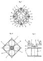
- the reversing circuit shown in Fig. 1 in plan view of its contact side has four single-contactors (V1, V2, R1, R2), which are arranged in a square.
- Each of the contactors V1, V2, R1, R2 has a coil 1, the contact bridges 2 move over plunger magnets.
- Two of the single-contactor contactors V1, V2 are used for forward travel with a direct current drive (not shown) which can be connected to the single-contactor contactors with a direct current source, while two further single-contactor contactors R1, R2 are used for reverse travel by means of the direct current drive.
- a contact piece 3 lies between each of the two coils 1 arranged in a square.
- the four contact pieces 3 are thus also arranged in a square.
- the contact pieces 3 each have a shape which is substantially the same as the shape of a right-angled, isosceles triangle.
- Acute-angled corners 4, 5 of the isosceles triangular contact pieces are cut perpendicular to their cathets 6, 7.
- bolts 8 are arranged for the external connections. Two of the bolts 8, which face each other, are connected to the DC power source (not shown).
- the two other bolts 8 are connected to a direct current drive (also not shown).
- the contact pieces 3 carry at their cut acute-angled corners 4, 5 fixed contacts, which are preferably through areas of the Contact pieces 3 are formed themselves, but can also be configured by contact surfaces placed on the contact pieces 3.
- the respective contact bridges 2 come into contact with the fixed contacts of the contact pieces 3 arranged on both sides of the excited coil 1, as can be seen in particular from FIG. 3, in which the contact bridge 2 is in the non-energized state of the coil 1 is out of contact with the contact pieces 3.
- Each contact piece 3 carries a blow magnet 9 on the bisector of the right angle at the level of the fixed contacts.
- the coils 1 are arranged in the area of the corners of a square magnetic yoke plate 11, which is provided with a reflux body 10 in the middle.
- a further circuit board 12 lies above the coils 1 and closes the respective magnetic circuits of the single-contactor contactors.
- This second circuit board 12 has holes for plunger magnet drive elements of the contact bridges 2.
Landscapes
- Physics & Mathematics (AREA)
- Electromagnetism (AREA)
- Relay Circuits (AREA)
- Electromagnets (AREA)
- Arc-Extinguishing Devices That Are Switches (AREA)
- Control Of Direct Current Motors (AREA)
Description
- Die vorliegende Erfindung betrifft eine Wendeschaltung zur Richtungsumkehr bei Gleichstromantrieben gemäß dem Oberbegriff des Anspruchs 1.
- Aus der US-A-18 47 081 ist eine Wendeschaltung der eingangs genannten Art bekannt. Die bekannte Wendeschaltung umfaßt vier Einfachschließerschütze, die Schützenspulen zum Bewegen zweipoliger Kontaktbrücken und mit äußeren Anschlüssen verbundene Festkontakte aufweisen.
- Die DE-A-24 18 930 offenbart eine gleichstrombetätigte elektromagnetische Wendeschaltung mit zwei als Wechselschütze ausgelegten, gegensinnig angesteuerten Schaltern, die jeweils zweipolige Kontaktbrücken aufweisen, mit denen wechselweise äußere Anschlüsse der Wendeschaltung Ober Festkontakte und die zweipoligen Kontaktbrücken mit weiteren äußeren Anschlüssen in Verbindung gebracht werden können. Diese bekannte Wendeschaltung mit Wechslerschützen weist eine relativ aufwendige Struktur mit hohem Raumbedarf auf und ist ferner in Hinsicht auf ihre Schaltleistung und Lebensdauer wegen der Verwendung von Ruhekontakten zum Obernehmen und Schalten der vollen elektrischen Leistung begrenzt.
- Die DE-C-525 108 betrifft eine U-förmige Tragschiene für eine Mehrzahl von Relais, die zusammen mit dem Relaisjoch und dem Relaiskernteil einstückig ausgeschaltet ist.
- Gegenüber diesem Stand der Technik liegt der vorliegenden Erfindung die Aufgabe zugrunde, eine Wendeschaltung der eingangs genannten Art so weiterzubilden, daß eine leistungsfähige und langlebige Schaltkontaktgabe bei raum- und materialsparender Bauweise der Wendeschaltung erreicht wird.
- Diese Aufgabe wird bei einer Wendeschaltung nach dem Oberbegriff des Anspruchs 1 durch die im kennzeichnenden Teil des Anspruchs 1 angegebenen Merkmale gelöst.
- Bei der erfindungsgemäßen Wendeschaltung werden ausschließlich Arbeitskontakte zur Kontaktgabe verwendet, so daß hohe Leistungen bei langer Kontaktlebensdauer geschaltet werden können. Die Anordnung der Einfachschließerschütze in Verbindung mit der entsprechenden Anordnung der Kontaktstücke ermöglicht eine sehr raumsparende Anordnung der äußeren Anschlüsse und der Festkontakte unter Vermeidung von Stromschienen zur Verbindung der Anschlüsse und der Festkontakte untereinander.
- Bevorzugte Ausgestaltungen der erfindungsgemäßen Wendeschaltung sind Gegenstand der Unteransprüche.
- Eine bevorzugte Ausführungsform wird nachfolgend unter Bezugnahme auf die beiliegenden Zeichnungen näher erläutert. Es zeigen:
- Fig. 1 eine Draufsicht auf die erfindungsgemäße Wendeschaltung;
- Fig. 2 eine Querschnittsdarstellung der erfindungsgemäßen Wendeschaltung; und
- Fig. 3 eine Seitenansicht der erfindungsgemäßen Wendeschaltung.
- Die in Fig. 1 in Draufsicht auf ihre Kontaktseite dargestellte Wendeschaltung weist vier Einfachschließerschütze (V₁, V₂, R₁, R₂) auf, die im Quadrat angeordnet sind. Jedes der Schütze V₁, V₂, R₁, R₂ weist eine Spule 1 auf, die über Tauchankermagnete Kontaktbrücken 2 bewegen. Zwei der Einfachschließerschütze V₁, V₂ dienen für die Vorwärtsfahrt mit einem durch die Einfachschließerschütze mit einer Gleichstromquelle verbindbaren Gleichstromantrieb (nicht dargestellt), während zwei weitere Einfachschließerschütze R₁, R₂ für die Rückwärtsfahrt mittels des Gleichstromantriebes dienen.
- Zwischen jeweils zwei der im Quadrat angeordneten Spulen 1 liegt jeweils ein Kontaktstück 3. Die vier Kontaktstücke 3 sind somit ebenfalls im Quadrat angeordnet. Die Kontaktstücke 3 haben jeweils eine Form, die im wesentlichen der Form eines rechtwinkeligen, gleichschenkeligen Dreiecks gleicht. Spitzwinkelige Ecken 4, 5 der gleichschenkeligen dreiecksförmigen Kontaktstücke sind senkrecht zu deren Katheten 6, 7 abgeschnitten. In den rechtwinkeligen Ecken der dreiecksförmigen Kontaktstücke 3 sind Bolzen 8 für die äußeren Anschlüsse angeordnet. Zwei der Bolzen 8, die einander gegenüberliegen, sind an die (nicht gezeigte) Gleichstromquelle angeschlossen. Die beiden anderen Bolzen 8 sind an einen Gleichstromantrieb (ebenfalls nicht dargestellt) angeschlossen. Die Kontaktstücke 3 tragen an ihren abgeschnittenen spitzwinkeligen Ecken 4, 5 Festkontakte, die vorzugsweise durch Bereiche der Kontaktstücke 3 selbst gebildet werden, jedoch auch durch auf die Kontaktstücke 3 aufgesetzte Kontaktflächen ausgestaltet sein können. Bei Erregung der Spulen 1 kommen die betreffenden Kontaktbrücken 2 jeweils mit den Festkontakten der zu beiden Seiten der erregten Spule 1 angeordneten Kontaktstücke 3 zur Anlage, wie insbesondere aus Fig. 3 ersichtlich ist, bei der sich die Kontaktbrücke 2 in dem nicht erregten Zustand der Spule 1 außer Anlage mit den Kontaktstücken 3 befindet.
- Auf der Winkelhalbierenden des rechten Winkels in Höhe der Festkontakte trägt jedes Kontaktstück 3 einen Blasmagneten 9.
- Wie in Fig. 2 dargestellt ist, sind die Spulen 1 im Bereich der Ecken einer quadratischen Magnetjochplatine 11 angeordnet, die in ihrer Mitte mit einem Rückflußkörper 10 versehen ist.
- Wie in Fig. 3 zu erkennen ist, liegt eine weitere Platine 12 oberhalb der Spulen 1 und schließt die jeweiligen Magnetkreise der Einfachschließerschütze. Diese zweite Platine 12 weist Bohrungen für Tauchankermagnet-Antriebselemente der Kontaktbrücken 2 auf.
Claims (4)
Applications Claiming Priority (2)
| Application Number | Priority Date | Filing Date | Title |
|---|---|---|---|
| DE3630657 | 1986-09-09 | ||
| DE19863630657 DE3630657A1 (de) | 1986-09-09 | 1986-09-09 | Wendeschaltung zur richtungsumkehr bei gleichstromantrieben |
Publications (2)
| Publication Number | Publication Date |
|---|---|
| EP0323461A1 EP0323461A1 (de) | 1989-07-12 |
| EP0323461B1 true EP0323461B1 (de) | 1992-04-01 |
Family
ID=6309212
Family Applications (1)
| Application Number | Title | Priority Date | Filing Date |
|---|---|---|---|
| EP87905206A Expired - Lifetime EP0323461B1 (de) | 1986-09-09 | 1987-07-31 | Wendeschaltung zur richtungsumkehr bei gleichstromantrieben |
Country Status (5)
| Country | Link |
|---|---|
| US (1) | US4947285A (de) |
| EP (1) | EP0323461B1 (de) |
| BG (1) | BG47048A3 (de) |
| DE (2) | DE3630657A1 (de) |
| WO (1) | WO1988002179A1 (de) |
Families Citing this family (1)
| Publication number | Priority date | Publication date | Assignee | Title |
|---|---|---|---|---|
| CN106449273A (zh) | 2016-09-29 | 2017-02-22 | 厦门宏发电力电器有限公司 | 一种带双微动开关的直流接触器 |
Family Cites Families (10)
| Publication number | Priority date | Publication date | Assignee | Title |
|---|---|---|---|---|
| DE525108C (de) * | 1931-05-21 | Fuld & Co Telephon Und Telegra | Tragschiene zur gemeinsamen Befestigung von Relais, deren Eisenkreis aus Stanzstuecken gebildet wird | |
| US427237A (en) * | 1890-05-06 | Executrix of abraham s | ||
| US1847081A (en) * | 1928-07-07 | 1932-03-01 | Westinghouse Electric & Mfg Co | Control system |
| DE1175322B (de) * | 1954-03-02 | 1964-08-06 | Vedder Gmbh Geb | Elektrischer Kreuzschalter |
| US2821639A (en) * | 1954-10-28 | 1958-01-28 | Westinghouse Electric Corp | Transistor switching circuits |
| US3264529A (en) * | 1963-01-11 | 1966-08-02 | Bell Telephone Labor Inc | Magnetically controlled stepping switch |
| US3694715A (en) * | 1970-09-28 | 1972-09-26 | Gen Electric | Contactless direct current motor reversing circuit |
| US3815060A (en) * | 1973-04-19 | 1974-06-04 | Square D Co | Electromagnetic contactor for battery powered vehicles |
| DE2448144C3 (de) * | 1974-10-09 | 1980-02-07 | Schaltbau Gesellschaft Mbh, 8000 Muenchen | Kontaktsystem fur einen um eine Achse drehbaren Klappanker |
| DE3201652A1 (de) * | 1982-01-21 | 1983-09-08 | Wilhelm Milles GmbH Ingenieurbüro, 4350 Recklinghausen | "einrichtung zur fahrtrichtungsumschaltung batteriebetriebener antriebsfahrzeuge in schlagwettergefaehrdeten grubenbetrieben" |
-
1986
- 1986-09-09 DE DE19863630657 patent/DE3630657A1/de not_active Withdrawn
-
1987
- 1987-07-31 WO PCT/EP1987/000421 patent/WO1988002179A1/de not_active Ceased
- 1987-07-31 DE DE8787905206T patent/DE3778030D1/de not_active Expired - Fee Related
- 1987-07-31 EP EP87905206A patent/EP0323461B1/de not_active Expired - Lifetime
- 1987-09-07 BG BG081130A patent/BG47048A3/xx unknown
-
1989
- 1989-03-08 US US07/332,451 patent/US4947285A/en not_active Expired - Fee Related
Also Published As
| Publication number | Publication date |
|---|---|
| BG47048A3 (en) | 1990-04-16 |
| EP0323461A1 (de) | 1989-07-12 |
| DE3630657A1 (de) | 1988-03-17 |
| DE3778030D1 (de) | 1992-05-07 |
| WO1988002179A1 (fr) | 1988-03-24 |
| US4947285A (en) | 1990-08-07 |
Similar Documents
| Publication | Publication Date | Title |
|---|---|---|
| DE3414731C2 (de) | Kleinstrelais | |
| DE69501597T2 (de) | Elektromagnetische Einrichtung | |
| DE3843359C2 (de) | ||
| EP1737717A1 (de) | Magnetschienenbremsvorichtung | |
| WO2013064629A1 (de) | Schalter für einen mehrpoligen gleichstrombetrieb | |
| EP1737718A1 (de) | Magnetschienenbremsvorrichtung | |
| DE3047608C2 (de) | Elektromagnetisches Relais | |
| DE2448144C3 (de) | Kontaktsystem fur einen um eine Achse drehbaren Klappanker | |
| WO1988002179A1 (fr) | Circuit d'inversion de sens pour entrainements a courant continu | |
| DE3249864C2 (de) | ||
| DE1614837C3 (de) | Elektromagnetisches Schütz | |
| EP0561485B1 (de) | Trennschalter mit hoher Schaltgeschwindigkeit | |
| DE1194003B (de) | Magnetischer Kreuzschienenschalter | |
| DE1301839B (de) | Magnetisch betaetigbare Schalteinrichtung fuer polarisierten Betrieb | |
| EP1143472B1 (de) | Elektromagnetisches Schaltgerät, insbesondere Schütz | |
| DE3224070C2 (de) | Polarisiertes Relais | |
| DE2402236C3 (de) | Steckbares, mit einem quaderförmigen Gehäuse versehenes, elektromagnetisches Relais | |
| DE3443556A1 (de) | Elektrisches schaltgeraet | |
| DE3528090C1 (de) | Elektromagnetisches Relais | |
| DE361328C (de) | Einrichtung zum Ausgleich der Schiefstellung an Verladebruecken u. dgl. | |
| EP0117879B1 (de) | Schaltbares Viertor | |
| AT359590B (de) | Bistabiles relais mit abgeschlossenen kontakten | |
| DE3223867C2 (de) | Polarisiertes Relais | |
| DE3246256C2 (de) | Elektromagnetisches Relais | |
| DE19804194C1 (de) | Piezoelektrisches Relais |
Legal Events
| Date | Code | Title | Description |
|---|---|---|---|
| PUAI | Public reference made under article 153(3) epc to a published international application that has entered the european phase |
Free format text: ORIGINAL CODE: 0009012 |
|
| 17P | Request for examination filed |
Effective date: 19880908 |
|
| AK | Designated contracting states |
Kind code of ref document: A1 Designated state(s): DE FR GB |
|
| RIN1 | Information on inventor provided before grant (corrected) |
Inventor name: HAPPACH, ANTON |
|
| GBC | Gb: translation of claims filed (gb section 78(7)/1977) | ||
| EL | Fr: translation of claims filed | ||
| 17Q | First examination report despatched |
Effective date: 19910516 |
|
| GRAA | (expected) grant |
Free format text: ORIGINAL CODE: 0009210 |
|
| AK | Designated contracting states |
Kind code of ref document: B1 Designated state(s): DE FR GB |
|
| ET | Fr: translation filed | ||
| REF | Corresponds to: |
Ref document number: 3778030 Country of ref document: DE Date of ref document: 19920507 |
|
| GBT | Gb: translation of ep patent filed (gb section 77(6)(a)/1977) | ||
| PLBE | No opposition filed within time limit |
Free format text: ORIGINAL CODE: 0009261 |
|
| STAA | Information on the status of an ep patent application or granted ep patent |
Free format text: STATUS: NO OPPOSITION FILED WITHIN TIME LIMIT |
|
| 26N | No opposition filed | ||
| PGFP | Annual fee paid to national office [announced via postgrant information from national office to epo] |
Ref country code: FR Payment date: 19930721 Year of fee payment: 7 |
|
| PGFP | Annual fee paid to national office [announced via postgrant information from national office to epo] |
Ref country code: GB Payment date: 19940620 Year of fee payment: 8 |
|
| PG25 | Lapsed in a contracting state [announced via postgrant information from national office to epo] |
Ref country code: FR Effective date: 19950331 |
|
| REG | Reference to a national code |
Ref country code: FR Ref legal event code: ST |
|
| PG25 | Lapsed in a contracting state [announced via postgrant information from national office to epo] |
Ref country code: GB Effective date: 19950731 |
|
| GBPC | Gb: european patent ceased through non-payment of renewal fee |
Effective date: 19950731 |
|
| PGFP | Annual fee paid to national office [announced via postgrant information from national office to epo] |
Ref country code: DE Payment date: 19980827 Year of fee payment: 12 |
|
| PG25 | Lapsed in a contracting state [announced via postgrant information from national office to epo] |
Ref country code: DE Free format text: LAPSE BECAUSE OF NON-PAYMENT OF DUE FEES Effective date: 20000503 |