EP0322935B1 - Verfahren und Vorrichtung zum Deponieren von lockerem Erdreich unter Wasser, insbesondere zum Abdecken eines Rohres oder dergleichen - Google Patents
Verfahren und Vorrichtung zum Deponieren von lockerem Erdreich unter Wasser, insbesondere zum Abdecken eines Rohres oder dergleichen Download PDFInfo
- Publication number
- EP0322935B1 EP0322935B1 EP19880202340 EP88202340A EP0322935B1 EP 0322935 B1 EP0322935 B1 EP 0322935B1 EP 19880202340 EP19880202340 EP 19880202340 EP 88202340 A EP88202340 A EP 88202340A EP 0322935 B1 EP0322935 B1 EP 0322935B1
- Authority
- EP
- European Patent Office
- Prior art keywords
- length
- pipe
- tubing
- apertures
- hoses
- Prior art date
- Legal status (The legal status is an assumption and is not a legal conclusion. Google has not performed a legal analysis and makes no representation as to the accuracy of the status listed.)
- Expired - Lifetime
Links
- 239000000463 material Substances 0.000 title claims description 26
- XLYOFNOQVPJJNP-UHFFFAOYSA-N water Substances O XLYOFNOQVPJJNP-UHFFFAOYSA-N 0.000 title claims description 25
- 238000000034 method Methods 0.000 title claims description 12
- 238000000151 deposition Methods 0.000 title claims description 3
- 239000000203 mixture Substances 0.000 claims description 14
- 230000007423 decrease Effects 0.000 claims description 2
- 238000009825 accumulation Methods 0.000 description 6
- 239000004576 sand Substances 0.000 description 4
- 239000002245 particle Substances 0.000 description 2
- 230000009286 beneficial effect Effects 0.000 description 1
Images


Classifications
-
- E—FIXED CONSTRUCTIONS
- E02—HYDRAULIC ENGINEERING; FOUNDATIONS; SOIL SHIFTING
- E02F—DREDGING; SOIL-SHIFTING
- E02F3/00—Dredgers; Soil-shifting machines
- E02F3/04—Dredgers; Soil-shifting machines mechanically-driven
- E02F3/88—Dredgers; Soil-shifting machines mechanically-driven with arrangements acting by a sucking or forcing effect, e.g. suction dredgers
- E02F3/90—Component parts, e.g. arrangement or adaptation of pumps
- E02F3/905—Manipulating or supporting suction pipes or ladders; Mechanical supports or floaters therefor; pipe joints for suction pipes
-
- E—FIXED CONSTRUCTIONS
- E02—HYDRAULIC ENGINEERING; FOUNDATIONS; SOIL SHIFTING
- E02F—DREDGING; SOIL-SHIFTING
- E02F5/00—Dredgers or soil-shifting machines for special purposes
- E02F5/02—Dredgers or soil-shifting machines for special purposes for digging trenches or ditches
- E02F5/10—Dredgers or soil-shifting machines for special purposes for digging trenches or ditches with arrangements for reinforcing trenches or ditches; with arrangements for making or assembling conduits or for laying conduits or cables
- E02F5/104—Dredgers or soil-shifting machines for special purposes for digging trenches or ditches with arrangements for reinforcing trenches or ditches; with arrangements for making or assembling conduits or for laying conduits or cables for burying conduits or cables in trenches under water
- E02F5/107—Dredgers or soil-shifting machines for special purposes for digging trenches or ditches with arrangements for reinforcing trenches or ditches; with arrangements for making or assembling conduits or for laying conduits or cables for burying conduits or cables in trenches under water using blowing-effect devices, e.g. jets
-
- E—FIXED CONSTRUCTIONS
- E02—HYDRAULIC ENGINEERING; FOUNDATIONS; SOIL SHIFTING
- E02F—DREDGING; SOIL-SHIFTING
- E02F5/00—Dredgers or soil-shifting machines for special purposes
- E02F5/02—Dredgers or soil-shifting machines for special purposes for digging trenches or ditches
- E02F5/12—Dredgers or soil-shifting machines for special purposes for digging trenches or ditches with equipment for back-filling trenches or ditches
- E02F5/125—Dredgers or soil-shifting machines for special purposes for digging trenches or ditches with equipment for back-filling trenches or ditches underwater
-
- E—FIXED CONSTRUCTIONS
- E02—HYDRAULIC ENGINEERING; FOUNDATIONS; SOIL SHIFTING
- E02F—DREDGING; SOIL-SHIFTING
- E02F5/00—Dredgers or soil-shifting machines for special purposes
- E02F5/02—Dredgers or soil-shifting machines for special purposes for digging trenches or ditches
- E02F5/14—Component parts for trench excavators, e.g. indicating devices travelling gear chassis, supports, skids
Definitions
- the invention relates to a process for depositing loose material under water, in which the loose material, mixed with water, is fed in at or near the bottom of the body of water through a pipe which has an outflow aperture and is directed downwards from a movable device, such as a vessel, while during the infeed of this mixture the device with the pipe is moved along a specific course, so that the outflowing mixture separates under water into water and loose material, the loose material being deposited on the bottom of the body of water.
- a movable device such as a vessel
- the object of the invention is to produce a process with which it is in fact possible to deposit loose material, in particular fine-grained loose material, such as fine sand, in the correct place in the correct form, without the loose material spreading in a more or less arbitrary manner.
- the mixture of water and loose material which is fed in through the pipe does not flow out through a single aperture, but through a large number of apertures lying in the direction of the course, while the delivery, i.e. the volume per unit time, flowing through the pipe is distributed among these apertures. Jets of mixture which have a small loose material outflow per aperture then emerge from the many apertures. If the pipe with the apertures is on or close to the area to be covered, then settling can take place a short distance away without the admixture of surrounding water.
- the pipe provided with outflow apertures and trailing along the bottom of the body of water or moving just above it forms a ridge of loose material which can serve to cover a line or cable, but which can also be used to build up a body, such as a sand body.
- the device for using the process according to the invention can be achieved in many different ways.
- the device according to the invention can be characterized in that the outflow mouth comprises a length of tubing which runs parallel to the bottom of the body of water and is provided with apertures distributed along the length of tubings, said apertures together with the then throttled end aperture of the length of tubing forming a passage which can process the delivery of the pipe.
- This length of tubing can be connected to the pipe by means of hinges with at least two pins standing at right angles to each other, and can be controlled in this way. It can therefore also be held just above the bottom, so that the outflow distance for the jets of mixture is as small as possible.
- the length of tubing can be a rigid pipe, but it can also be a flexible hose.
- the condition is that it is provided with series of outflow apertures along a great length, for example 10 to 15 meters.
- the outflow apertures are preferably disposed in the top part of the length of tubing.
- This flap can be made of tight material, but is preferably made of material which is permeable to water, but which retains the loose material. The loose material is in this way expelled from the jets and forced by the flap to settle on the bottom. Admixture with surrounding water can be fully counteracted in this way.
- Apertures can, however, also be provided in the bottom part of the length of tubing.
- the length of tubing is a flexible hose, which is dragged along the bottom, it preferably has the apertures in the top parts of the side wall. However, it is then possible to connect several lines, such as, for example, two or more hoses which are fixed to a manifold, which is in turn fixed to the end of the pipe.
- the outermost hoses can be largely or fully left without lateral apertures, and the outermost hoses are longer than the innermost. A good lateral boundary is obtained in this way.
- control can be carried out by controlling the bottom end of the pipe, for example by means of cardan joints with operating cylinders disposed therein.
- the length of tubing is a funnel which from the pipe onwards has a flow cross section which increases in the direction of flow and is provided with outflow apertures in the wall.
- the increase in cross section results in a speed reduction, and thus a reduction in the emerging partial jets.
- the height of this funnel can decrease in the direction of flow, so that only one outlet slot is left at the end of the funnel.
- the funnel can also pass gradually in the direction of flow from the circular cross section of the pipe to a horizontal crescent shape.
- the shape itself then provides protection against the admixture of surrounding water, and this shape is particularly beneficial for the covering of a pipe.
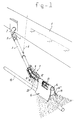
- Fig. 1 indicates by 1 the side of a hopper.
- a downward-slanting pipe 3 Coming out of this side wall of the hopper via an elbow 2 is a downward-slanting pipe 3, which is connected to the elbow by means of hinge arms 4, said hinge being straddled by a bellows 5.
- Said pipe 3 is suspended from the hopper by cables, such as the cable 6.
- a pipe to be covered, which can lie in a channel, is indicated by 15.
- a flap 16 is placed over the tubing 12 provided with slits 13 and - as shown in Fig. 3 - is held at some distance from the top wall of the length of tubing 12 by a support 17, and on either side thereof hangs down and is in contact with the bottom 18 of the water.
- the flaps 16 can, if desired, be provided on the front or rear end with a cross flap 16"' which does not entirely reach the bottom.
- the mixture emerging from the slits 13 forms an accumulation, indicated in its entirety by 19, under the flaps 16′, 16 ⁇ (vide Fig. 3).
- the hopper 1 is advanced parallel to the course of the pipe 15 to be covered, so that during this advance an unbroken accumulation or sand ridge which covers the pipe 15 is formed.
- a flexible hose 21 which hangs down in a curve and rests with a long part 21′ on the course to be covered, is connected to the pipe section 11 of the pipe 3, which is designed in the same way as shown in Fig. 1.
- This hose is provided in the side walls with slit-type out-flow apertures 22, from which mixture jets 23 emerge.
- the hose part 21′ Since the hose is moved forward with the hopper along the course of the pipe 15, the hose part 21′ will remain stably in the accumulation forming.
- the accumulation 19′ obtained is flatter in shape.
- Fig. 4 shows how an accumulation 28 can be formed by means of two hoses 24, 25 with lateral outflow apertures 26, 27.
- the outflow apertures can here be disposed largely or entirely in the sides of the hoses facing each other. In an embodiment with four hoses it is possible to make the two outermost hoses considerably longer than the two innermost hoses.
- the outermost hoses can here be made tight over a large part or even fully, and serve to prevent lateral flowing away of the loose material mixture from the two innermost hoses, in such a way that most of the loose material settles between the two outermost hoses.
- the hoses 26, 27 respectively are fixed to a manifold 29, which bears a rod 30, on which the flap 31 rests, said flap extending on either side of the hoses 26 and 27.
- Fig. 7 shows an embodiment in which the length of tubing is formed by a funnel 32 with a large number of elongated outflow apertures 33 in the bottom face.
- the funnel is also crescent-shaped in cross section, as indicated at 35, with outlet apertures 36 in the bottom part. This funnel encloses the object 37 to be covered from above.
Landscapes
- Engineering & Computer Science (AREA)
- Mining & Mineral Resources (AREA)
- Mechanical Engineering (AREA)
- Civil Engineering (AREA)
- General Engineering & Computer Science (AREA)
- Structural Engineering (AREA)
- Feeding, Discharge, Calcimining, Fusing, And Gas-Generation Devices (AREA)
- Rigid Pipes And Flexible Pipes (AREA)
- Processing Of Solid Wastes (AREA)
- Underground Or Underwater Handling Of Building Materials (AREA)
Claims (18)
- Verfahren zum Ablagern von Schüttgut unter Wasser, bei dem das mit Wasser vermischte Schüttgut am oder in der Nähe des Gewässergrundes durch ein Rohr (3) eingeleitet wird, das eine Ausströmöffnung aufweist und von einer beweglichen Einrichtung, z. B. einem Schiff (1), nach unten gerichtet ist, wobei die Einrichtung mit dem Rohr während des Einleitens dieser Mischung entlang eines bestimmten Kurses (15) bewegt wird, so daß unter Wasser eine Trennung der ausströmenden Mischung in Wasser und Schüttgut erfolgt, das abgelagert wird, dadurch gekennzeichnet, daß, in Richtung des Kurses (15) betrachtet, die Schüttgutmischung über eine große Strecke des Kurses, durch in der Wandung, nach dem Ende des Rohres (3) vorgesehene einander in Richtung des Kurses aufeinander folgende Öffnungen (13,22) separiert so ausgetragen wird, daß der Austrag aus dem Rohr (3) über diese große Strecke verteilt wird.
- Vorrichtung zur Durchführung des Verfahrens nach Anspruch 1, mit einem Schiff (1) und einem hiervon abwärts verlaufenden an seinem Ende eine Auslaßmündung aufweisenden Rohr (3), dadurch gekennzeichnet, daß die Auslaßmündung ein parallel zum Gewässergrund verlaufendes Rohrstück (12) umfaßt, das mit Ausströmöffnungen (13) versehen ist, die über die Länge des Rohrstücks (12) verteilt sind und, möglicherweise zusammen mit der dann gedrosselten Endöffnung (14) des Rohrstücks (12) einen Durchfluß bilden, der den Austrag des Rohres (3) ermöglicht.
- Vorrichtung nach Anspruch 2, dadurch gekennzeichnet, daß das die Auslaßmündung bildende Rohrstück (12) mit dem Rohr durch Scharniere (8, 9) mit wenigstens zwei rechtwinklig zueinander stehenden Gelenkstiften verbunden oder seinerseits mit Scharnieren mit rechtwinklig zueinander stehenden Gelenkstiften versehen ist, so daß die Auslaßmündung über externe Einrichtungen in die gewünschte Position steuerbar ist.
- Vorrichtung nach Anspruch 3, dadurch gekennzeichnet, daß das Rohrstück ein starres Rohr (12) ist.
- Vorrichtung nach Anspruch 2, 3 oder 4, dadurch gekennzeichnet, daß oben auf dem Rohrstück oder dem starren Rohr (12) eine Abdeckung angeordnet ist, die sich auf beiden Seiten des Rohres erstreckt, und deren Länge zumindest der Länge des mit Öffnungen (13) versehenen Rohrstücks (12) entspricht.
- Vorrichtung nach Anspruch 5, dadurch gekennzeichnet, daß diese Abdeckung (16) beidseitig des Rohrstücks am vorderen und hinteren Ende durch eine Querabdeckung (16" ') miteinander verbunden sind, die eine geringere Höhe aufweist als die Abdeckung (16), mit der sie verbunden ist.
- Vorrichtung nach Anspruch 2 oder 3, dadurch gekennzeichnet, daß das Rohrstück ein flexibler Schlauch (21) ist, dessen auf dem Grund liegender Abschnitt Ausströmöffnungen (22) aufweist.
- Vorrichtung nach Anspruch 5, 6 oder 7, dadurch gekennzeichnet, daß das Rohrstück zwei oder mehr Abschnitte (24, 25) oder Schläuche (26, 27) aufweist, die über einen Verteiler (29) mit dem Rohr verbunden sind.
- Vorrichtung nach Anspruch 8, dadurch gekennzeichnet, daß, wenn mehr als zwei Schläuche vorhanden sind, die äußeren Schläuche überwiegend oder völlig ohne seitliche Öffnungen ausgebildet sein können und länger sind als die inneren Schläuche.
- Vorrichtung nach einem oder mehreren der vorhergehenden Ansprüche 2 bis 9, dadurch gekennzeichnet, daß die Öffnungen in dem oberen Teil des Rohrstücks angeordnet sind.
- Vorrichtung nach einem oder mehreren der vorhergehenden Ansprüche 2 bis 10, dadurch gekennzeichnet, daß Öffnungen im unteren Teil des Rohrstücks angeordnet sind.
- Vorrichtung nach Anspruch 8 oder 9, dadurch gekennzeichnet, daß zwischen den beiden oder mehreren am Rohrverteiler (29) angeschlossenen Schläuchen (26, 27) ein Halter (30) für eine flexible Abdeckung vorgesehen ist.
- Vorrichtung nach Anspruch 2 oder 3, dadurch gekennzeichnet, daß das Rohrstück die Form eines Trichters (32) aufweist, der vom Rohr ausgehend einen sich in Strömungsrichtung vergrößernden Durchflußquerschnitt aufweist und in der Wandung mit Auslaßöffnungen (33) versehen ist.
- Vorrichtung nach Anspruch 13, dadurch gekennzeichnet, daß die Höhe des Trichters in Strömungsrichtung abnimmt, um am Ende des Trichters (32) einen Auslaufschlitz (34) zu bilden.
- Vorrichtung nach Anspruch 13, dadurch gekennzeichnet, daß der Trichter in Strömungsrichtung allmählich vom runden Querschnitt des Rohres in eine horizontale sichelförmige Form (35) übergeht.
- Vorrichtung nach den Ansprüchen 13, 14 oder 15, dadurch gekennzeichnet, daß die Öffnungen (33, 36) in der unteren Wandung des Trichters angeordnet sind.
- Verfahren nach Anspruch 1 unter Verwendung der Vorrichtung nach einem oder mehreren der Ansprüche 2 bis 16, dadurch gekennzeichnet, daß ein länglicher Gegenstand, z. B. eine Pipeline (15) oder ein Kabel bedeckt wird.
- Verfahren nach Anspruch 1, unter Verwendung der Vorrichtung nach einem oder mehreren der Ansprüche 2 bis 16, dadurch gekennzeichnet, daß durch aufeinanderfolgende nebeneinander und/oder übereinander liegende Bahnen ein Körper gebildet wird.
Applications Claiming Priority (2)
| Application Number | Priority Date | Filing Date | Title |
|---|---|---|---|
| NL8703137 | 1987-12-24 | ||
| NL8703137A NL8703137A (nl) | 1987-12-24 | 1987-12-24 | Werkwijze en inrichting voor het deponeren van stortgoed onder water, in het bijzonder het bedekken van een leiding of dergelijke. |
Publications (2)
| Publication Number | Publication Date |
|---|---|
| EP0322935A1 EP0322935A1 (de) | 1989-07-05 |
| EP0322935B1 true EP0322935B1 (de) | 1993-06-02 |
Family
ID=19851153
Family Applications (1)
| Application Number | Title | Priority Date | Filing Date |
|---|---|---|---|
| EP19880202340 Expired - Lifetime EP0322935B1 (de) | 1987-12-24 | 1988-10-19 | Verfahren und Vorrichtung zum Deponieren von lockerem Erdreich unter Wasser, insbesondere zum Abdecken eines Rohres oder dergleichen |
Country Status (7)
| Country | Link |
|---|---|
| EP (1) | EP0322935B1 (de) |
| DE (1) | DE3881499T2 (de) |
| DK (1) | DK165341C (de) |
| ES (1) | ES2040833T3 (de) |
| IE (1) | IE62585B1 (de) |
| NL (1) | NL8703137A (de) |
| NO (1) | NO163420C (de) |
Families Citing this family (6)
| Publication number | Priority date | Publication date | Assignee | Title |
|---|---|---|---|---|
| EP0816574A1 (de) * | 1996-07-03 | 1998-01-07 | Jan De Nul N.V. | Vorrichtung zum Verlegen von Röhren oder Kabeln auf dem Meeresboden |
| GB2473471B (en) * | 2009-09-11 | 2011-11-09 | Technip France | Method of laying a pipeline in a seabed |
| ITMI20110556A1 (it) * | 2011-04-05 | 2012-10-06 | Saipem Spa | Dispositivo spargitore di materiale inerte fluidificato per seppellire una tubazione disposta in un corpo d'acqua e metodo per spargere materiale inerte fluidificato su una tubazione disposta in un corpo d'acqua |
| NL2013770B9 (en) * | 2014-11-11 | 2017-03-29 | Ihc Holland Ie Bv | Hopper dredger with flocculant injection system. |
| US10858802B2 (en) * | 2018-09-10 | 2020-12-08 | Deepwater Corrosion Services, Inc. | Hydraulic excavation around a pipeline buried under shallow water |
| CN109469139A (zh) * | 2018-11-08 | 2019-03-15 | 马鞍山沐及信息科技有限公司 | 一种清淤船 |
Family Cites Families (4)
| Publication number | Priority date | Publication date | Assignee | Title |
|---|---|---|---|---|
| GB1163508A (en) * | 1968-05-27 | 1969-09-10 | Shell Intenat Res Mij N V | Method of horizontally or substantially horizontally laying a pipeline or other object in a trench in a formation underlying a body of water |
| NL7806662A (en) * | 1978-06-20 | 1979-12-27 | Sediment Science Limited | Erodable river-bed sediment stabilisation system - deposits solids suspended in non-hardening material directly on sediment |
| DK155458C (da) * | 1981-06-24 | 1990-01-29 | Carl Peter Skroeder | Maskine til anbringelse af langstrakte ledninger i bunden under et vandomraade |
| NL8201952A (nl) * | 1982-05-12 | 1983-12-01 | Baggermaatschappij Holland B V | Werkwijze en inrichting voor het onder water leggen van een pijpleiding, in het bijzonder een leiding welke lichter is dan water. |
-
1987
- 1987-12-24 NL NL8703137A patent/NL8703137A/nl not_active Application Discontinuation
-
1988
- 1988-10-19 ES ES88202340T patent/ES2040833T3/es not_active Expired - Lifetime
- 1988-10-19 EP EP19880202340 patent/EP0322935B1/de not_active Expired - Lifetime
- 1988-10-19 DE DE19883881499 patent/DE3881499T2/de not_active Expired - Fee Related
- 1988-10-24 IE IE320588A patent/IE62585B1/en not_active IP Right Cessation
- 1988-12-13 DK DK692288A patent/DK165341C/da not_active IP Right Cessation
- 1988-12-22 NO NO885723A patent/NO163420C/no unknown
Also Published As
| Publication number | Publication date |
|---|---|
| IE883205L (en) | 1989-06-24 |
| EP0322935A1 (de) | 1989-07-05 |
| IE62585B1 (en) | 1995-02-08 |
| NO163420B (no) | 1990-02-12 |
| DK692288D0 (da) | 1988-12-13 |
| DK165341B (da) | 1992-11-09 |
| DE3881499D1 (de) | 1993-07-08 |
| DE3881499T2 (de) | 1993-09-09 |
| NO885723L (no) | 1989-06-26 |
| ES2040833T3 (es) | 1993-11-01 |
| DK692288A (da) | 1989-06-25 |
| DK165341C (da) | 1993-04-05 |
| NO163420C (no) | 1990-05-23 |
| NO885723D0 (no) | 1988-12-22 |
| NL8703137A (nl) | 1989-07-17 |
Similar Documents
| Publication | Publication Date | Title |
|---|---|---|
| EP0322935B1 (de) | Verfahren und Vorrichtung zum Deponieren von lockerem Erdreich unter Wasser, insbesondere zum Abdecken eines Rohres oder dergleichen | |
| US8469636B2 (en) | Commodity splitter for an air delivery system | |
| CN105828901B (zh) | 沉淀池用沉淀物排出装置 | |
| PL89705B1 (de) | ||
| JPH09508307A (ja) | 織布フィルター | |
| CN216163362U (zh) | 便携式生态园林施工放样工具 | |
| JPS6019371B2 (ja) | 水底覆土用砂撤き装置 | |
| CN208743334U (zh) | 土壤污染修复材料布置装置 | |
| CN206580329U (zh) | 一种物料整形机构 | |
| CN206529956U (zh) | 自灌溉植物墙扇形模块 | |
| CN109778863A (zh) | 动水岩溶通道封堵负压流体携带钻孔投料装置及使用方法 | |
| CN205495049U (zh) | 一种旋转母支管反洗水分配装置 | |
| US4568461A (en) | Apparatus for distributing a substance over a surface | |
| CA1266462A (en) | Gravity blending apparatus and methods of gravity blending | |
| US2253727A (en) | Portable dam for irrigating ditches | |
| CN213801939U (zh) | 一种可调节输送量的导流弯部件 | |
| CN210482453U (zh) | 用于河道引水灌溉引流装置 | |
| JPS59115757A (ja) | 籾摺装置 | |
| JPH0512234B2 (de) | ||
| SU1625941A1 (ru) | Рыбопропускное сооружение | |
| JP2000166342A (ja) | 風調節機能付き風分岐装置及び粒剤散布装置 | |
| US9273445B2 (en) | Fluidified inert material spreading device for burying an underwater pipeline, and method of spreading fluidified inert material over an underwater pipeline | |
| RU2129359C1 (ru) | Дождевальный аппарат | |
| SU1491949A1 (ru) | Рыбоотвод рыбозащитного устройства | |
| SU757646A1 (ru) | Пульпопровод для намыва минерального грунта на поверхности слабых грунтов или плодородных почв · 1 |
Legal Events
| Date | Code | Title | Description |
|---|---|---|---|
| PUAI | Public reference made under article 153(3) epc to a published international application that has entered the european phase |
Free format text: ORIGINAL CODE: 0009012 |
|
| AK | Designated contracting states |
Kind code of ref document: A1 Designated state(s): BE DE ES FR GB IT NL |
|
| 17P | Request for examination filed |
Effective date: 19890512 |
|
| 17Q | First examination report despatched |
Effective date: 19910404 |
|
| GRAA | (expected) grant |
Free format text: ORIGINAL CODE: 0009210 |
|
| AK | Designated contracting states |
Kind code of ref document: B1 Designated state(s): BE DE ES FR GB IT NL |
|
| ITF | It: translation for a ep patent filed | ||
| REF | Corresponds to: |
Ref document number: 3881499 Country of ref document: DE Date of ref document: 19930708 |
|
| ET | Fr: translation filed | ||
| REG | Reference to a national code |
Ref country code: ES Ref legal event code: FG2A Ref document number: 2040833 Country of ref document: ES Kind code of ref document: T3 |
|
| PLBE | No opposition filed within time limit |
Free format text: ORIGINAL CODE: 0009261 |
|
| STAA | Information on the status of an ep patent application or granted ep patent |
Free format text: STATUS: NO OPPOSITION FILED WITHIN TIME LIMIT |
|
| 26N | No opposition filed | ||
| REG | Reference to a national code |
Ref country code: GB Ref legal event code: IF02 |
|
| PGFP | Annual fee paid to national office [announced via postgrant information from national office to epo] |
Ref country code: FR Payment date: 20021017 Year of fee payment: 15 |
|
| PGFP | Annual fee paid to national office [announced via postgrant information from national office to epo] |
Ref country code: BE Payment date: 20021021 Year of fee payment: 15 |
|
| PGFP | Annual fee paid to national office [announced via postgrant information from national office to epo] |
Ref country code: DE Payment date: 20021029 Year of fee payment: 15 |
|
| PGFP | Annual fee paid to national office [announced via postgrant information from national office to epo] |
Ref country code: ES Payment date: 20030923 Year of fee payment: 16 |
|
| PGFP | Annual fee paid to national office [announced via postgrant information from national office to epo] |
Ref country code: NL Payment date: 20030930 Year of fee payment: 16 |
|
| PGFP | Annual fee paid to national office [announced via postgrant information from national office to epo] |
Ref country code: GB Payment date: 20031006 Year of fee payment: 16 |
|
| PG25 | Lapsed in a contracting state [announced via postgrant information from national office to epo] |
Ref country code: BE Free format text: LAPSE BECAUSE OF NON-PAYMENT OF DUE FEES Effective date: 20031031 |
|
| BERE | Be: lapsed |
Owner name: HOLLANDSCHE *BETON GROEP N.V. Effective date: 20031031 |
|
| PG25 | Lapsed in a contracting state [announced via postgrant information from national office to epo] |
Ref country code: DE Free format text: LAPSE BECAUSE OF NON-PAYMENT OF DUE FEES Effective date: 20040501 |
|
| PG25 | Lapsed in a contracting state [announced via postgrant information from national office to epo] |
Ref country code: FR Free format text: LAPSE BECAUSE OF NON-PAYMENT OF DUE FEES Effective date: 20040630 |
|
| REG | Reference to a national code |
Ref country code: FR Ref legal event code: ST |
|
| PG25 | Lapsed in a contracting state [announced via postgrant information from national office to epo] |
Ref country code: GB Free format text: LAPSE BECAUSE OF NON-PAYMENT OF DUE FEES Effective date: 20041019 |
|
| PG25 | Lapsed in a contracting state [announced via postgrant information from national office to epo] |
Ref country code: ES Free format text: LAPSE BECAUSE OF NON-PAYMENT OF DUE FEES Effective date: 20041020 |
|
| PG25 | Lapsed in a contracting state [announced via postgrant information from national office to epo] |
Ref country code: NL Free format text: LAPSE BECAUSE OF NON-PAYMENT OF DUE FEES Effective date: 20050501 |
|
| GBPC | Gb: european patent ceased through non-payment of renewal fee |
Effective date: 20041019 |
|
| NLV4 | Nl: lapsed or anulled due to non-payment of the annual fee |
Effective date: 20050501 |
|
| PG25 | Lapsed in a contracting state [announced via postgrant information from national office to epo] |
Ref country code: IT Free format text: LAPSE BECAUSE OF NON-PAYMENT OF DUE FEES Effective date: 20051019 |
|
| REG | Reference to a national code |
Ref country code: ES Ref legal event code: FD2A Effective date: 20041020 |