EP0322596B1 - Procédé et dispositif pour transporter un fluide prêt à bouillir - Google Patents
Procédé et dispositif pour transporter un fluide prêt à bouillir Download PDFInfo
- Publication number
- EP0322596B1 EP0322596B1 EP88120195A EP88120195A EP0322596B1 EP 0322596 B1 EP0322596 B1 EP 0322596B1 EP 88120195 A EP88120195 A EP 88120195A EP 88120195 A EP88120195 A EP 88120195A EP 0322596 B1 EP0322596 B1 EP 0322596B1
- Authority
- EP
- European Patent Office
- Prior art keywords
- container
- liquid
- heat
- pressure
- displacement member
- Prior art date
- Legal status (The legal status is an assumption and is not a legal conclusion. Google has not performed a legal analysis and makes no representation as to the accuracy of the status listed.)
- Expired - Lifetime
Links
- 238000000034 method Methods 0.000 title description 8
- 239000012530 fluid Substances 0.000 title description 4
- 239000007788 liquid Substances 0.000 claims description 35
- 238000006073 displacement reaction Methods 0.000 claims description 12
- 239000002904 solvent Substances 0.000 claims description 6
- 238000001179 sorption measurement Methods 0.000 claims description 6
- 238000010521 absorption reaction Methods 0.000 claims description 4
- 230000001172 regenerating effect Effects 0.000 claims description 4
- 238000009835 boiling Methods 0.000 claims description 3
- 230000008859 change Effects 0.000 description 7
- 239000006096 absorbing agent Substances 0.000 description 6
- 238000007667 floating Methods 0.000 description 5
- 230000008901 benefit Effects 0.000 description 4
- 238000005191 phase separation Methods 0.000 description 4
- 239000003507 refrigerant Substances 0.000 description 4
- 239000000126 substance Substances 0.000 description 4
- 238000001816 cooling Methods 0.000 description 3
- 239000000203 mixture Substances 0.000 description 3
- 239000012071 phase Substances 0.000 description 3
- 230000008569 process Effects 0.000 description 3
- 239000000498 cooling water Substances 0.000 description 2
- 239000012528 membrane Substances 0.000 description 2
- 230000000737 periodic effect Effects 0.000 description 2
- 239000012808 vapor phase Substances 0.000 description 2
- 230000006835 compression Effects 0.000 description 1
- 238000007906 compression Methods 0.000 description 1
- 238000010276 construction Methods 0.000 description 1
- 238000005265 energy consumption Methods 0.000 description 1
- 230000005484 gravity Effects 0.000 description 1
- 238000010438 heat treatment Methods 0.000 description 1
- 230000003993 interaction Effects 0.000 description 1
- 239000007791 liquid phase Substances 0.000 description 1
- 239000000463 material Substances 0.000 description 1
- 238000005381 potential energy Methods 0.000 description 1
- 238000004886 process control Methods 0.000 description 1
- 230000009467 reduction Effects 0.000 description 1
- 230000000630 rising effect Effects 0.000 description 1
- 238000000926 separation method Methods 0.000 description 1
- 238000013517 stratification Methods 0.000 description 1
- 231100000331 toxic Toxicity 0.000 description 1
- 230000002588 toxic effect Effects 0.000 description 1
- XLYOFNOQVPJJNP-UHFFFAOYSA-N water Substances O XLYOFNOQVPJJNP-UHFFFAOYSA-N 0.000 description 1
Images

Classifications
-
- F—MECHANICAL ENGINEERING; LIGHTING; HEATING; WEAPONS; BLASTING
- F04—POSITIVE - DISPLACEMENT MACHINES FOR LIQUIDS; PUMPS FOR LIQUIDS OR ELASTIC FLUIDS
- F04B—POSITIVE-DISPLACEMENT MACHINES FOR LIQUIDS; PUMPS
- F04B19/00—Machines or pumps having pertinent characteristics not provided for in, or of interest apart from, groups F04B1/00 - F04B17/00
- F04B19/20—Other positive-displacement pumps
- F04B19/24—Pumping by heat expansion of pumped fluid
-
- F—MECHANICAL ENGINEERING; LIGHTING; HEATING; WEAPONS; BLASTING
- F04—POSITIVE - DISPLACEMENT MACHINES FOR LIQUIDS; PUMPS FOR LIQUIDS OR ELASTIC FLUIDS
- F04F—PUMPING OF FLUID BY DIRECT CONTACT OF ANOTHER FLUID OR BY USING INERTIA OF FLUID TO BE PUMPED; SIPHONS
- F04F1/00—Pumps using positively or negatively pressurised fluid medium acting directly on the liquid to be pumped
- F04F1/02—Pumps using positively or negatively pressurised fluid medium acting directly on the liquid to be pumped using both positively and negatively pressurised fluid medium, e.g. alternating
- F04F1/04—Pumps using positively or negatively pressurised fluid medium acting directly on the liquid to be pumped using both positively and negatively pressurised fluid medium, e.g. alternating generated by vaporising and condensing
Definitions
- the invention relates to a device for conveying boiling liquids, with a lockable inflow and outflow container, the inner surface of which has a lower temperature in the lower region than in the upper region, and can be moved up and down in the displacer such that the liquid-vapor interface is moved to zones of different temperatures.
- the solution pump of a sorption plant presents considerable structural difficulties, although the performance for this component is comparatively low.
- the pressure difference to be bridged depends on the pair of materials used, consisting of refrigerant and solvent.
- a frequently used pair of substances is NH3 / H2O, at which pressure differences of 20 bar and more can occur.
- the problems that arise, which are similar for many other substance pairs, are poor efficiency and cavitation problems, as well as the leakage of refrigerant, which is often environmentally harmful or toxic.
- the costs for this component in particular in the case of large cooling or heating capacities, can also be disproportionately high compared to the costs of the entire system.
- the invention is therefore based on the object of providing a device of the type mentioned, in which no highly stressed wear parts, in particular no membranes, are required, and in which a faster and more economical method of operation than in known devices of this type can be achieved.
- GB-A-2 019 486 describes a device for conveying boiling liquids, with a container provided with a lockable inflow and outflow, the inner surface of which has a lower temperature in the lower region than in the upper region, and in which a displacement body of this type can be moved up and down periodically that the liquid-vapor interface is moved to zones of different temperatures.
- a pump is provided with a chamber which is partially filled with a liquid, and there is a vapor / liquid interface between two areas of different temperatures.
- a floating body which makes an upward and downward movement and moves the interface between the two areas back and forth, so that the vapor pressure on the liquid changes.
- the upward and downward movement of the float causes liquid to move against a force.
- the floating body can move freely in the chamber in the upward and downward direction.
- the upward and downward movement of the floating body is not primarily caused by changes in temperature and pressure, but either by an interplay between the buoyancy and gravity of the floating body or by utilizing the flow forces of the conveying liquid when flowing in or out onto a resistance body attached to the bottom of the floating body.
- the term "load” is understood to mean the pressure of a fluid, which can be a gas or a liquid or a mixture of a gas and a liquid.
- the displacer is movable by external drive and the container wall is divided into zones of increasing temperatures, the zones between the lowest (coldest) and the top (hottest) zone being designed as a regenerative heat exchanger.
- the device can advantageously be installed in a sorption system (absorption chiller, heat pump or heat transformer and resorption chiller, heat pump or heat transformer) to convey the solvent and / or means of transport.
- a sorption system absorption chiller, heat pump or heat transformer and resorption chiller, heat pump or heat transformer
- a hydraulic displacement unit for moving the displacement body by the pressure energy of the liquid transport or solvent and / or an electromagnetic drive for periodic up and down movement of the displacement body.
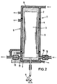
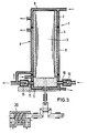
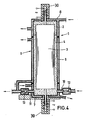
- Figures 1-4 of the drawing show an embodiment of a device in four different operating states.
- the device consists of a container 1, which encloses a working space 2, into which a displacer 3 is fitted such that a narrow cylinder gap 4 remains between the wall of the container 1 and the displacer 3.
- the displacer 3 experiences an oscillating translational movement within the working space 2 via a drive 5.
- the walls 6 as well as the bottom 7 and cover 8 of the container are designed in a suitable manner, for example double-walled and divided, in such a way that they can take over the function of separate heat exchangers, in case of media of appropriate temperature be flowed through.
- the wall temperature of the container 1 increases in the axial direction towards the head.
- the walls are, for example, divided several times and fluids of different temperatures flow through them, so that a "cold zone” forms in the lower part of the container 1 and a “hot zone” in the head of the container 1.
- the wall part 9 between the cover 8 and the bottom 7 is designed on the one hand in a suitable manner as a regenerative heat exchanger, so that a temperature gradient is established in the cylinder axis direction, and on the other hand the cavity of the wall part 9 is flowed through by the liquid conveyed to high pressure after a completed working cycle for a subsequent heat exchange .
- In the lower part of the container 1 there are an inlet opening 10 to the low-pressure part of a sorption system (not shown) and an outlet opening 11 to the high-pressure part of the sorption system, both openings being provided with a check valve 12 and 13, respectively.
- a liquid level forms within the cylinder gap 4 between the wall of the container 1 and the displacer 3, which can be regarded as the phase boundary between the vapor space located above and the liquid space located underneath, as follows will be described - always a residual mass of liquid and vapor phase remains in the system. Due to the temperature stratification in the container wall, with each change in the liquid level in the narrow cylinder gap 4 between the container 1 and the displacer 3, a heat supply or removal, thus a temperature change at the phase separation layer, is produced. The temperature of this separation layer, at which ideally there is a constant phase equilibrium, is the sole determinant of the pressure in the entire container 1, a certain container pressure being approximately assigned to a discrete water level. So if the level of the phase boundary is shifted by a movement of the displacer 3, the tank pressure is changed in the same way.
- the device has the task of conveying the refrigerant-enriched solution emerging from the absorber from the low absorber pressure (e.g. 4 bar) to the generator at high pressure (e.g. 20 bar).
- the pressure of the liquid, but not its temperature, should be increased in order to keep the energy consumption as low as possible.
- the mixture of steam and liquid remaining in the system is subcooled in the cold zone compared to the entry temperature of this solution by cooling the container bottom 7 with e.g. is branched off in front of the absorber and is therefore colder than the solution considered here, is flowed through, so that a relative negative pressure (e.g. 3.8 bar) to the absorber is established in container 1, whereby the check valve 12 in the inlet opening 10 opens.
- a relative negative pressure e.g. 3.8 bar
- a relative overpressure to the generator must be created in the container 1 (e.g. 20.2 bar) so that the check valve 13 in the outlet opening 11 opens. This is done by internal heat exchange by flowing a liquid through the hot lid 8 of the container 1, the temperature of which is higher than the equilibrium temperature of the refrigerant at this pressure, for example the degassed solution after the generator exits.
- the changes in the state of the cycle for the system under consideration are explained below with reference to FIGS. 1 to 4.
- Fig. 1 according to state (1), the displacer 3 is shown in the bottom dead center.
- the volume of steam in the head of the container 1 represents the control volume, which is as follows goes through a cycle.
- the phase separation mirror is in the hot zone; thus there is a relative overpressure in the container 1, the lid 8 of which is heated with an in-process liquid of a suitable temperature, in comparison with the generator of the sorption system, so that the check valve 13 in the outlet channel 11 is open.
- the displacer 3 is now moved upwards, the phase separation layer moves between the liquid remaining in the working space and the associated vapor phase in the direction of lower temperatures. Since both check valves 11, 12 are closed when the state changes from (1) to (2), this runs isochorically.
- a part of the control volume, which was vaporous in state (1), is liquefied during this change of state and gives off the amount of heat q 1 to the container wall, which is stored by it.
- the check valve 13 in the outlet opening 11 opens, and the solution is displaced from the lower part of the container 1 into the generator by a further downward movement of the displacer 3 while maintaining the high pressure.
- the heat q41 must be supplied in the hot lid 8 from the solution flowing through the hot head, whereby further condensate can evaporate again from the control volume.
- the energy expenditure for operating the device described with ideal process control consists of the supply of the specific amount of heat q41 and the comparatively small volume change work P23, which the liquid flowing into the container 1 at the control volume.
- the process provides the volume change work P41 on the displaced liquid and the heat q23, which is given as useful heat to the consumer-side heat transfer medium in the example discussed here, as well as the difference in heat flows q12 - q31.
- the volume change work P Nutz can be generated. Furthermore, the heat is q23 at the useful temperature level.
- a hydraulic displacement unit 20 can also be used for the movement of the displacement body 3, which uses the pressure energy of the liquid transport or solvent.
- an electromagnetic drive 30 is shown for the periodic up and down movement of the displacer 3, which can be arranged within the displacer 3, whereby the particular advantage is achieved that the working space 2 is completely closed, so that an undesirable leakage of Liquid is prevented even more safely.
- the invention offers the advantage of an operationally reliable mode of operation since highly stressed wear parts, in particular no membranes, are required.
- the device according to the invention also has the advantage of particularly fast and economical operation.
Landscapes
- Engineering & Computer Science (AREA)
- Mechanical Engineering (AREA)
- General Engineering & Computer Science (AREA)
- Filling Or Discharging Of Gas Storage Vessels (AREA)
- Sorption Type Refrigeration Machines (AREA)
- Meat, Egg Or Seafood Products (AREA)
- Electromagnetic Pumps, Or The Like (AREA)
- Extraction Or Liquid Replacement (AREA)
Claims (4)
- Dispositif pour transporter des fluides aptes à entrer en ébullition, comportant un récipient (1) muni d'une admission et d'une évacuation obturables, dont la surface intérieure présente, dans la région inférieure, une température plus basse que dans la région supérieure, et dans lequel un corps refouleur (3) peut accomplir périodiquement un va-et-vient vertical de telle sorte que la couche limite fluide-vapeur soit décomposée en des zones de températures différentes, caractérisé par le fait que le corps refouleur (3) est mobile par l'intermédiaire d'un entraînement extérieur (5, 20 ; 30), et la paroi du récipient est scindée en des zones de températures croissantes, les zones situées entre la zone la plus basse (la plus froide), et la zone la plus haute (la plus chaude), étant réalisées sous la forme d'un échangeur thermique à action régénératrice.
- Dispositif selon la revendication 1, caractérisé par le fait que, en vue d'acheminer l'agent de dissolution et/ou de transport, il est incorporé dans une installation de sorption (machine frigorifique, pompe à chaleur ou transformateur thermique agissant par absorption, ainsi que machine frigorifique, pompe à chaleur ou transformateur thermique agissant par résorption).
- Dispositif selon la revendication 1, caractérisé par un ensemble refouleur hydraulique (20), pour imprimer un mouvement au corps refouleur (3) par l'énergie de la pression de l'agent fluide respectif de transport ou de dissolution.
- Dispositif selon la revendication 1, caractérisé par un entraînement électromagnétique (30) assurant le va-et-vient vertical périodique du corps refouleur (3).
Applications Claiming Priority (2)
| Application Number | Priority Date | Filing Date | Title |
|---|---|---|---|
| DE19873744487 DE3744487A1 (de) | 1987-12-30 | 1987-12-30 | Verfahren und vorrichtung zur foerderung von siedefaehigen fluessigkeiten |
| DE3744487 | 1987-12-30 |
Publications (2)
| Publication Number | Publication Date |
|---|---|
| EP0322596A1 EP0322596A1 (fr) | 1989-07-05 |
| EP0322596B1 true EP0322596B1 (fr) | 1992-04-08 |
Family
ID=6343823
Family Applications (1)
| Application Number | Title | Priority Date | Filing Date |
|---|---|---|---|
| EP88120195A Expired - Lifetime EP0322596B1 (fr) | 1987-12-30 | 1988-12-03 | Procédé et dispositif pour transporter un fluide prêt à bouillir |
Country Status (5)
| Country | Link |
|---|---|
| US (1) | US4954048A (fr) |
| EP (1) | EP0322596B1 (fr) |
| JP (1) | JPH01262376A (fr) |
| DE (2) | DE3744487A1 (fr) |
| NO (1) | NO168726C (fr) |
Families Citing this family (5)
| Publication number | Priority date | Publication date | Assignee | Title |
|---|---|---|---|---|
| US4987954A (en) * | 1988-11-28 | 1991-01-29 | Boucher Robert J | Fuel reactor |
| US6123512A (en) * | 1997-08-08 | 2000-09-26 | The United States Of America As Represented By The Administrator Of The National Aeronautics And Space Administration | Heat driven pulse pump |
| RU2480623C1 (ru) * | 2012-03-22 | 2013-04-27 | Александр Дмитриевич Савчук | Теплоиспользующий компрессор |
| PL240516B1 (pl) * | 2018-01-09 | 2022-04-19 | Dobrianski Jurij | Maszyna parowa |
| DE102019129495B3 (de) * | 2019-10-31 | 2021-04-15 | Deutsches Zentrum für Luft- und Raumfahrt e.V. | Verdichteranordnung, Wärmepumpenanordnung und Verfahren zum Betreiben der Verdichteranordnung |
Family Cites Families (12)
| Publication number | Priority date | Publication date | Assignee | Title |
|---|---|---|---|---|
| FR429602A (fr) * | 1911-05-08 | 1911-09-27 | Joseph Maurer | Appareil à refouler les liquides sous pression |
| US2853953A (en) * | 1952-05-07 | 1958-09-30 | Zander & Ingestroem | Liquid pumps |
| DE1048152B (de) * | 1956-06-21 | 1958-12-31 | Austria Email Ag | Vorrichtung zum intermittierenden Foerdern von Fluessigkeiten |
| US3285001A (en) * | 1965-03-04 | 1966-11-15 | Conductron Corp | Thermal fluid moving apparatus |
| FR2357762A1 (fr) * | 1976-07-06 | 1978-02-03 | Lemasson Yves | Procede de pompage de l'eau par l'energie solaire |
| GB2015654A (en) * | 1978-03-06 | 1979-09-12 | Alsacienne & Dauphinoise | A water pumping device using a condensable gas source of energy |
| GB2019486B (en) * | 1978-03-07 | 1982-05-19 | Atomic Energy Authority Uk | Pumps |
| US4281969A (en) * | 1979-06-25 | 1981-08-04 | Doub Ernest L Jun | Thermal pumping device |
| EP0048139A1 (fr) * | 1980-09-16 | 1982-03-24 | The Calor Group Limited | Dispositif de pompage |
| DD219060A3 (de) * | 1983-07-11 | 1985-02-20 | Dsf Waermeanlagenbau | Absorptionswaermepumpe |
| DE3331887A1 (de) * | 1983-09-03 | 1985-03-21 | VEB Wärmeanlagenbau Deutsche Demokratische Republik, DDR 1020 Berlin | Absorptionswaermepumpe |
| DE3344937A1 (de) * | 1983-12-13 | 1985-06-20 | Achim Dr.-Ing. 6636 Hülzweiler Wilhelm | Verfahren und vorrichtung zum foerdern von wasser |
-
1987
- 1987-12-30 DE DE19873744487 patent/DE3744487A1/de not_active Withdrawn
-
1988
- 1988-12-03 DE DE8888120195T patent/DE3869931D1/de not_active Expired - Fee Related
- 1988-12-03 EP EP88120195A patent/EP0322596B1/fr not_active Expired - Lifetime
- 1988-12-06 NO NO885409A patent/NO168726C/no unknown
- 1988-12-28 JP JP63329536A patent/JPH01262376A/ja active Pending
- 1988-12-30 US US07/292,335 patent/US4954048A/en not_active Expired - Fee Related
Also Published As
| Publication number | Publication date |
|---|---|
| EP0322596A1 (fr) | 1989-07-05 |
| US4954048A (en) | 1990-09-04 |
| DE3869931D1 (de) | 1992-05-14 |
| NO168726C (no) | 1992-03-25 |
| DE3744487A1 (de) | 1989-07-13 |
| NO168726B (no) | 1991-12-16 |
| JPH01262376A (ja) | 1989-10-19 |
| NO885409L (no) | 1989-07-03 |
| NO885409D0 (no) | 1988-12-06 |
Similar Documents
| Publication | Publication Date | Title |
|---|---|---|
| DE1653404A1 (de) | Auslassventil fuer Kolbenpumpen | |
| DE3037114A1 (de) | Kuehlsystem mit unterdruckanwendung fuer eine kunststofform | |
| EP0322596B1 (fr) | Procédé et dispositif pour transporter un fluide prêt à bouillir | |
| DE2311423C3 (de) | Vorrichtung zur Übertragung von Wärme von einem niedrigeren zu einem höheren Temperaturpegel | |
| EP0437772A1 (fr) | Système de refroidissement à ébullition pour un moteur à combustion interne refroidi par liquide | |
| DE2300377A1 (de) | Kolbenkompressor fuer ein kuehlmittel | |
| DE2923621A1 (de) | Thermischer antrieb | |
| DE2245035A1 (de) | Vorrichtung mit einem waermeerzeugenden teil, beispielsweise kompressor fuer ein kuehlsystem | |
| AT163344B (de) | Kühlanlage mit Kolbenverdichter | |
| DE2538730A1 (de) | Kuehlwaerme-rueckgewinnungsanlage | |
| DE3511339C2 (de) | Kolbenstangenabdichtung für einen Stirling-Motor | |
| DE1601467A1 (de) | Heissgaskolbenmaschine | |
| DE2530483A1 (de) | Heissgaskolbenmaschine mit einer vorrichtung zum regeln der gewichtsmenge eines in einem arbeitsraum befindlichen arbeitsmediums | |
| DE2732158A1 (de) | Waermepumpe | |
| DE1501062A1 (de) | Kaelteerzeugungsanlage | |
| DE2919263A1 (de) | Waermekraftmaschine | |
| CH521516A (de) | Wärme-Kraftmaschine | |
| DE69114474T2 (de) | Einführvorrichtung einer Kolbenpumpe für Saturationsflüssigkeiten. | |
| DE968680C (de) | Saugdruckregler | |
| DE3606935C2 (fr) | ||
| DE1260494B (de) | Als Heissgaskraftmaschine oder insbesondere als Kaltgas-Kuehlmaschine arbeitende Kolbenmaschine | |
| DE227529C (fr) | ||
| DE1095057B (de) | Fluessigkeitsfeder | |
| AT157549B (de) | Wärmekraftmaschine. | |
| DE374184C (de) | Maschine zur Ausnutzung von Temperaturgefaellen |
Legal Events
| Date | Code | Title | Description |
|---|---|---|---|
| PUAI | Public reference made under article 153(3) epc to a published international application that has entered the european phase |
Free format text: ORIGINAL CODE: 0009012 |
|
| AK | Designated contracting states |
Kind code of ref document: A1 Designated state(s): BE DE FR GB IT LU NL SE |
|
| 17P | Request for examination filed |
Effective date: 19891109 |
|
| 17Q | First examination report despatched |
Effective date: 19900720 |
|
| GRAA | (expected) grant |
Free format text: ORIGINAL CODE: 0009210 |
|
| ITF | It: translation for a ep patent filed | ||
| AK | Designated contracting states |
Kind code of ref document: B1 Designated state(s): BE DE FR GB IT LU NL SE |
|
| REF | Corresponds to: |
Ref document number: 3869931 Country of ref document: DE Date of ref document: 19920514 |
|
| ET | Fr: translation filed | ||
| GBT | Gb: translation of ep patent filed (gb section 77(6)(a)/1977) | ||
| PG25 | Lapsed in a contracting state [announced via postgrant information from national office to epo] |
Ref country code: GB Effective date: 19921203 |
|
| PG25 | Lapsed in a contracting state [announced via postgrant information from national office to epo] |
Ref country code: SE Effective date: 19921204 |
|
| PG25 | Lapsed in a contracting state [announced via postgrant information from national office to epo] |
Ref country code: LU Free format text: LAPSE BECAUSE OF NON-PAYMENT OF DUE FEES Effective date: 19921231 Ref country code: BE Effective date: 19921231 |
|
| PLBE | No opposition filed within time limit |
Free format text: ORIGINAL CODE: 0009261 |
|
| STAA | Information on the status of an ep patent application or granted ep patent |
Free format text: STATUS: NO OPPOSITION FILED WITHIN TIME LIMIT |
|
| 26N | No opposition filed | ||
| BERE | Be: lapsed |
Owner name: RENDAMAX B.V. Effective date: 19921231 |
|
| GBPC | Gb: european patent ceased through non-payment of renewal fee |
Effective date: 19921203 |
|
| PGFP | Annual fee paid to national office [announced via postgrant information from national office to epo] |
Ref country code: NL Payment date: 19941231 Year of fee payment: 7 |
|
| EUG | Se: european patent has lapsed |
Ref document number: 88120195.8 Effective date: 19930709 |
|
| PG25 | Lapsed in a contracting state [announced via postgrant information from national office to epo] |
Ref country code: NL Effective date: 19960701 |
|
| NLV4 | Nl: lapsed or anulled due to non-payment of the annual fee |
Effective date: 19960701 |
|
| PGFP | Annual fee paid to national office [announced via postgrant information from national office to epo] |
Ref country code: FR Payment date: 19961118 Year of fee payment: 9 |
|
| PGFP | Annual fee paid to national office [announced via postgrant information from national office to epo] |
Ref country code: DE Payment date: 19961209 Year of fee payment: 9 |
|
| PG25 | Lapsed in a contracting state [announced via postgrant information from national office to epo] |
Ref country code: FR Free format text: THE PATENT HAS BEEN ANNULLED BY A DECISION OF A NATIONAL AUTHORITY Effective date: 19971231 |
|
| PG25 | Lapsed in a contracting state [announced via postgrant information from national office to epo] |
Ref country code: DE Free format text: LAPSE BECAUSE OF NON-PAYMENT OF DUE FEES Effective date: 19980901 |
|
| REG | Reference to a national code |
Ref country code: FR Ref legal event code: ST |
|
| PG25 | Lapsed in a contracting state [announced via postgrant information from national office to epo] |
Ref country code: IT Free format text: LAPSE BECAUSE OF NON-PAYMENT OF DUE FEES;WARNING: LAPSES OF ITALIAN PATENTS WITH EFFECTIVE DATE BEFORE 2007 MAY HAVE OCCURRED AT ANY TIME BEFORE 2007. THE CORRECT EFFECTIVE DATE MAY BE DIFFERENT FROM THE ONE RECORDED. Effective date: 20051203 |