EP0322522B1 - Dichtband - Google Patents
Dichtband Download PDFInfo
- Publication number
- EP0322522B1 EP0322522B1 EP88116785A EP88116785A EP0322522B1 EP 0322522 B1 EP0322522 B1 EP 0322522B1 EP 88116785 A EP88116785 A EP 88116785A EP 88116785 A EP88116785 A EP 88116785A EP 0322522 B1 EP0322522 B1 EP 0322522B1
- Authority
- EP
- European Patent Office
- Prior art keywords
- sealing strip
- opening
- sealing
- edge
- sealing tape
- Prior art date
- Legal status (The legal status is an assumption and is not a legal conclusion. Google has not performed a legal analysis and makes no representation as to the accuracy of the status listed.)
- Expired - Lifetime
Links
- 238000007789 sealing Methods 0.000 title claims abstract description 38
- 229920001343 polytetrafluoroethylene Polymers 0.000 claims abstract description 11
- 239000004810 polytetrafluoroethylene Substances 0.000 claims abstract description 11
- 239000011324 bead Substances 0.000 claims abstract description 9
- -1 polytetrafluoroethylene Polymers 0.000 claims abstract 2
- 238000010276 construction Methods 0.000 abstract 1
- 239000000463 material Substances 0.000 description 6
- 238000004519 manufacturing process Methods 0.000 description 4
- 229920001971 elastomer Polymers 0.000 description 2
- 239000000806 elastomer Substances 0.000 description 2
- 230000001788 irregular Effects 0.000 description 2
- 238000000465 moulding Methods 0.000 description 2
- 239000004033 plastic Substances 0.000 description 2
- 229920003023 plastic Polymers 0.000 description 2
- 239000000565 sealant Substances 0.000 description 2
- 239000002253 acid Substances 0.000 description 1
- 150000007513 acids Chemical class 0.000 description 1
- 239000002390 adhesive tape Substances 0.000 description 1
- 150000001875 compounds Chemical class 0.000 description 1
- 238000005260 corrosion Methods 0.000 description 1
- 230000007797 corrosion Effects 0.000 description 1
- 229920000295 expanded polytetrafluoroethylene Polymers 0.000 description 1
- 239000002920 hazardous waste Substances 0.000 description 1
- 239000003350 kerosene Substances 0.000 description 1
- 238000012423 maintenance Methods 0.000 description 1
- 238000000034 method Methods 0.000 description 1
- 239000003921 oil Substances 0.000 description 1
- 239000000126 substance Substances 0.000 description 1
Images
Classifications
-
- B—PERFORMING OPERATIONS; TRANSPORTING
- B64—AIRCRAFT; AVIATION; COSMONAUTICS
- B64C—AEROPLANES; HELICOPTERS
- B64C1/00—Fuselages; Constructional features common to fuselages, wings, stabilising surfaces or the like
- B64C1/14—Windows; Doors; Hatch covers or access panels; Surrounding frame structures; Canopies; Windscreens accessories therefor, e.g. pressure sensors, water deflectors, hinges, seals, handles, latches, windscreen wipers
-
- Y—GENERAL TAGGING OF NEW TECHNOLOGICAL DEVELOPMENTS; GENERAL TAGGING OF CROSS-SECTIONAL TECHNOLOGIES SPANNING OVER SEVERAL SECTIONS OF THE IPC; TECHNICAL SUBJECTS COVERED BY FORMER USPC CROSS-REFERENCE ART COLLECTIONS [XRACs] AND DIGESTS
- Y10—TECHNICAL SUBJECTS COVERED BY FORMER USPC
- Y10T—TECHNICAL SUBJECTS COVERED BY FORMER US CLASSIFICATION
- Y10T428/00—Stock material or miscellaneous articles
- Y10T428/24—Structurally defined web or sheet [e.g., overall dimension, etc.]
- Y10T428/24479—Structurally defined web or sheet [e.g., overall dimension, etc.] including variation in thickness
- Y10T428/24488—Differential nonuniformity at margin
-
- Y—GENERAL TAGGING OF NEW TECHNOLOGICAL DEVELOPMENTS; GENERAL TAGGING OF CROSS-SECTIONAL TECHNOLOGIES SPANNING OVER SEVERAL SECTIONS OF THE IPC; TECHNICAL SUBJECTS COVERED BY FORMER USPC CROSS-REFERENCE ART COLLECTIONS [XRACs] AND DIGESTS
- Y10—TECHNICAL SUBJECTS COVERED BY FORMER USPC
- Y10T—TECHNICAL SUBJECTS COVERED BY FORMER US CLASSIFICATION
- Y10T428/00—Stock material or miscellaneous articles
- Y10T428/24—Structurally defined web or sheet [e.g., overall dimension, etc.]
- Y10T428/24777—Edge feature
-
- Y—GENERAL TAGGING OF NEW TECHNOLOGICAL DEVELOPMENTS; GENERAL TAGGING OF CROSS-SECTIONAL TECHNOLOGIES SPANNING OVER SEVERAL SECTIONS OF THE IPC; TECHNICAL SUBJECTS COVERED BY FORMER USPC CROSS-REFERENCE ART COLLECTIONS [XRACs] AND DIGESTS
- Y10—TECHNICAL SUBJECTS COVERED BY FORMER USPC
- Y10T—TECHNICAL SUBJECTS COVERED BY FORMER US CLASSIFICATION
- Y10T428/00—Stock material or miscellaneous articles
- Y10T428/26—Web or sheet containing structurally defined element or component, the element or component having a specified physical dimension
-
- Y—GENERAL TAGGING OF NEW TECHNOLOGICAL DEVELOPMENTS; GENERAL TAGGING OF CROSS-SECTIONAL TECHNOLOGIES SPANNING OVER SEVERAL SECTIONS OF THE IPC; TECHNICAL SUBJECTS COVERED BY FORMER USPC CROSS-REFERENCE ART COLLECTIONS [XRACs] AND DIGESTS
- Y10—TECHNICAL SUBJECTS COVERED BY FORMER USPC
- Y10T—TECHNICAL SUBJECTS COVERED BY FORMER US CLASSIFICATION
- Y10T428/00—Stock material or miscellaneous articles
- Y10T428/28—Web or sheet containing structurally defined element or component and having an adhesive outermost layer
- Y10T428/2804—Next to metal
-
- Y—GENERAL TAGGING OF NEW TECHNOLOGICAL DEVELOPMENTS; GENERAL TAGGING OF CROSS-SECTIONAL TECHNOLOGIES SPANNING OVER SEVERAL SECTIONS OF THE IPC; TECHNICAL SUBJECTS COVERED BY FORMER USPC CROSS-REFERENCE ART COLLECTIONS [XRACs] AND DIGESTS
- Y10—TECHNICAL SUBJECTS COVERED BY FORMER USPC
- Y10T—TECHNICAL SUBJECTS COVERED BY FORMER US CLASSIFICATION
- Y10T428/00—Stock material or miscellaneous articles
- Y10T428/31504—Composite [nonstructural laminate]
- Y10T428/3154—Of fluorinated addition polymer from unsaturated monomers
- Y10T428/31544—Addition polymer is perhalogenated
-
- Y—GENERAL TAGGING OF NEW TECHNOLOGICAL DEVELOPMENTS; GENERAL TAGGING OF CROSS-SECTIONAL TECHNOLOGIES SPANNING OVER SEVERAL SECTIONS OF THE IPC; TECHNICAL SUBJECTS COVERED BY FORMER USPC CROSS-REFERENCE ART COLLECTIONS [XRACs] AND DIGESTS
- Y10—TECHNICAL SUBJECTS COVERED BY FORMER USPC
- Y10T—TECHNICAL SUBJECTS COVERED BY FORMER US CLASSIFICATION
- Y10T428/00—Stock material or miscellaneous articles
- Y10T428/31504—Composite [nonstructural laminate]
- Y10T428/31678—Of metal
- Y10T428/31692—Next to addition polymer from unsaturated monomers
- Y10T428/31699—Ester, halide or nitrile of addition polymer
Definitions
- the invention relates to a sealing tape for sealing the joints and gaps between the edge of an opening in an aircraft fuselage and the cover closing the opening in the form of a profile piece with a - in cross section - relatively wide flat part and a narrower, thickened bead part.
- the reaction of the sealant is waited for before the aircraft is checked for leaks, for example with a sprinkler system.
- the cover In the event of leaks, the cover must be unscrewed again, the sealing compound removed and the sealing process repeated. It takes about 12 hours to react out of the sealant. So that is the sealing of the openings is very time-consuming, in particular disturbing that the seals are not of a constant quality.
- DE-A-2 919 958 shows, in accordance with the preamble of claim 1, a flange seal which is designed such that the flat part can only be deformed to a limited extent, while the bead part is resilient or plastically flexible.
- the flat part and the bead part should consist of two materials, one of which, elastic or plastic, is resistant to corrosion by the medium to be sealed, while the other material is resistant to mechanical loads.
- material combinations are elastomers of different hardness of different bases or elastomers with plastics, e.g. B. PTFE indicated.
- the invention has for its object to provide a sealing tape of the type mentioned, which ensures an evenly good seal everywhere even with irregular gaps and gaps between the edge of the opening and the edge of the lid.
- the one-piece profile consists of expanded PTFE.
- the bead is in the assembled state of the sealing tape at the location of the edge of the opening, which corresponds to the largest gap between the edge of the opening and the edge of the lid.
- the sealing tape has good sealing properties, a relatively high compressibility, so that even with irregular gaps and gaps between the edge of the opening and the edge of the lid a uniformly good seal is achieved everywhere.
- the sealing tape With the sealing tape, openings can be quickly equipped with seals.
- the lid fastener e.g. B. screws can be screwed in easily. To do this, the sealing tape is simply pierced with a pointed tool at the relevant hole locations. The expanded PTFE attaches to the screw and ensures tightness even in these sensitive areas.
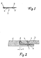
- a sealing tape 1 consists of a one-piece profile piece made of expanded polytetrafluoroethylene (PTFE).
- the profile piece has a relatively wide flat part 3, which is approximately 3-4 cm wide and approximately 1 mm thick, and a narrower, thickened bead part 2 with a thickness of approximately 3.5 mm.
- the opening of an aircraft fuselage G is closed by a cover D, the edge of the cover being spaced some distance from the opening edge of the aircraft fuselage G and being fastened with a screw 7 seated in the bore 6 of the cover such that the outside of the fuselage G is aligned with the outside of the cover D.
- the sealing tape 1 which changes its shape due to its special properties so that it completely fills the gap between the lid edge and the opening edge.
- the width S of the gap is subject to fluctuations to which the sealing tape adapts well.
- the screw 7 engaging in a hole 9 in the opening edge passes through a hole 8 in the sealing tape 1.
- the hole 8 becomes after the sealing tape has been attached created at the edge of the opening with a pointed tool by simply piercing the sealing tape.
- the sealing tape 1 which is made of PTFE, has a particular stretchability and a special tensile strength, as a result of which the sealing tape has particularly good sealing properties.
- the material PTFE has in the sealing tape according to the invention, i.e. in the special application of sealing the gaps and joints between openings and covers of aircraft fuselages, the advantage that due to its absolute chemical resistance, neither aircraft gasoline (kerosene) nor aggressive acids and oils, as are usually used in aircraft hydraulics, can attack the seal.
- the sealing tape 1 according to the invention is produced by extruding the profile through a molding nozzle.
- the production of the sealing tape corresponds essentially to the production of film parts made of the appropriate material.
Landscapes
- Engineering & Computer Science (AREA)
- Mechanical Engineering (AREA)
- Aviation & Aerospace Engineering (AREA)
- Sealing Material Composition (AREA)
- Gasket Seals (AREA)
- Adhesive Tapes (AREA)
- Shielding Devices Or Components To Electric Or Magnetic Fields (AREA)
- Package Closures (AREA)
- Control And Other Processes For Unpacking Of Materials (AREA)
- Adhesives Or Adhesive Processes (AREA)
Description
- Die Erfindung betrifft ein Dichtband zum Abdichten der Fugen und Spalten zwischen dem Rand einer Öffnung in einem Flugzeugrumpf und dem die Öffnung verschließendem Deckel in Form eines Profilstücks mit einem - jeweils im Querschnitt - relativ breiten Flachteil und einem schmaleren, verdickten Wulstteil.
- Damit die in einem Flugzeugrumpf aufgenommenen Teile (Instrumente, Leitungen und dergleichen) für Wartungs- und Reparaturarbeiten, wenn nicht von innen her, so doch von außen zugänglich sind, werden in dem Rumpf üblicherweise Öffnungen vorgesehen, die vor Inbetriebnahme des Flugzeugs von passenden Deckeln verschlossen werden. Um diese wasserdicht zu verschließen, verwendete man bislang sogenannte Selbstformdichtungen, das sind Zwei-Komponenten-Dichtungen, die angemischt und dann sehr dünn auf die Dichtfläche aufgetragen werden, bevor der Deckel angeschraubt oder anderweitig festgezogen wird.
- Zur Prüfung der Dichtigkeit wird das Ausreagieren der Dichtmasse abgewartet, bevor das Flugzeug zum Beispiel mit einer Berieselungsanlage auf Dichtigkeit geprüft wird. Bei Undichtigkeiten muß der Deckel wieder abgeschraubt, die Dichtmasse entfernt und der Dichtungsvorgang wiederholt werden. Das Ausreagieren der Dichtungsmasse benötigt etwa 12 Stunden. Damit ist das Abdichten der Öffnungen sehr zeitraubend, wobei insbesondere stört, daß die Dichtungen nicht von gleichbleibender Qualität sind.
- Unproblematisch ist auch nicht die Beseitigung der alten, unbrauchbaren Dichtungen; denn diese müssen als Sondermüll behandelt werden.
- Die DE-A- 2 919 958 zeigt in Übereinstimmung mit dem Oberbegriff des Anspruchs 1 eine Flanschdichtung, die derart ausgebildet ist, daß sich der Flachteil nur begrenzt verformen läßt, während der Wulstteil elastisch oder plastisch nachgiebig ist. Speziell sollen Flachteil und Wulstteil aus zwei Werkstoffen bestehen, von denen der eine, elastische oder plastische Werkstoff gegen Korrosion durch das abzudichtende Medium beständig ist, während der andere Werkstoff widerstandsfähig gegenüber mechanischen Belastungen ist. Als Materialkombinationen werden Elastomere unterschiedlicher Härte verschiedener Basis oder Elastomere mit Kunststoffen, z. B. PTFE, angegeben.
- Nun sind derartige Flanschdichtungen aus zwei verschiedenen Werkstoffen in der Herstellung teuer. Wenn, wie es bei der bekannten Dichtung der Fall ist, der Flachteil nur sehr begrenzt verformen läßt, eignen sich derartige Dichtungen kaum zum Abdichten der Fugen und Spalten zwischen einem Öffnungsrand in einem Flugzeugrumpf und dem dazugehörigen Deckelrand.
- Der Erfindung liegt die Aufgabe zugrunde, ein Dichtband der eingangs genannten Art anzugeben, das auch bei unregelmäßigen Lücken und Spalten zwischen Öffnungsrand und Deckelrand überall eine gleichmäßig gute Abdichtung gewährleistet.
- Gelöst wird diese Aufgabe durch die Erfindung dadurch, daß das einstückige Profil aus expandiertem PTFE besteht.
- Der Wulst befindet sich im montierten Zustand des Dichtbandes an der Stelle des Randes der Öffnung, der der größten Lücke zwischen Öffnungsrand und Deckelrand entspricht.
- Dadurch, daß das Profilstück aus expandiertem PTFE besteht, besitzt das Dichtband bei guten Dichtungseigenschaften eine relativ hohe Kompressibilität, so daß auch bei unregelmäßigen Lücken und Spalten zwischen Öffnungsrand und Deckelrand überall eine gleichmäßig gute Abdichtung erreicht wird.
- Mit dem Dichtband können Öffnungen in kurzer Zeit mit Dichtungen ausgestattet werden. Die Deckel-Befestigungsmittel, z. B. Schrauben, können mühelos eingeschraubt werden. Dazu wird das Dichtband an den betreffenden Bohrungsstellen einfach mit einem spitzen Werkzeug durchstochen. Das expandierte PTFE legt sich an die Schraube an und gewährleistet auch an diesen empfindlichen Stellen Dichtigkeit.
- Im folgenden werden Ausführungsbeispiele der Erfindung anhand der Zeichnung näher erläutert. Es zeigen:
- Fig. 1
- eine Querschnittansicht eines Dichtbands, und
- Fig. 2
- einen Randbereich einer von einem Deckel abgedichteten verschlossenen Öffnung in einem Flugzeugrumpf.
- Nach Fig. 1 besteht ein Dichtband 1 aus einem einstückigen Profilstück aus expandiertem Polytetrafluorethylen (PTFE). Das Profilstück besitzt einen relativ breiten Flachteil 3, der ca. 3-4 cm breit und ca. 1 mm dick ist, sowie einen schmaleren, verdickten Wulstteil 2 mit einer Dicke von etwa 3,5 mm.
- Auf der Unterseite des Flachteils 3 befinden sich Selbstklebebänder 4 und 5, mit denen das Dichtband in einem abzudichtendem Bereich festgeklebt wird.
- Wie Fig. 2 zeigt, wird die Öffnung eines Flugzeugrumpfes G von einem Deckel D verschlossen, wobei der Rand des Deckels in einigem Abstand vom Öffnungrand des Flugzeugrumpfs G beabstandet ist und so mit einer in der Bohrung 6 des Deckels sitzenden Schraube 7 befestigt ist, daß die Außenseite des Flugzeugsrumpfs G mit der Außenseite des Deckels D fluchtet. In dem Spalt zwischen Deckelrand und Öffnungsrand befindet sich das Dichtband 1, welches aufgrund seiner besonderen Eigenschaften seine Form so verändert, daß es die Lücke zwischen Deckelrand und Öffnungsrand vollständig ausfüllt.
- Die Breite S des Spalts unterliegt Schwankungen, denen sich das Dichtband gut anpaßt. Die in einer Bohrung 9 im Öffnungsrand eingreifende Schraube 7 durchsetzt ein Loch 8 des Dichtbands 1. Das Loch 8 wird nach dem Anbringen des Dichtbands am Öffnungsrand mit einem spitzen Werkzeug geschaffen, indem das Dichtband einfach durchstoßen wird.
- Herstellungsbedingt besitzt das aus PTFE bestehende Dichtband 1 besondere Dehnungsfähigkeit und eine besondere Zugfestigkeit, wodurch das Dichtband besonders gute Dichtungseigenschaft besitzt. Der Werkstoff PTFE hat bei dem erfindungsgemäßen Dichtband, d.h. bei dem speziellen Anwendungsfall des Abdichtens der Spalten und Fugen zwischen Öffnungen und Deckeln von Flugzeugrümpfen, den Vorteil, daß aufgrund seiner absoluten Chemikalienbeständigkeit weder Flugzeugbenzin (Kerosin) noch agressive Säuren und Öle, wie sie üblicherweise in der Flugzeughydraulik verwendet werden, die Dichtung angreifen können.
- Das Herstellen des neuerungsgemäßen Dichtbandes 1 erfolgt durch Extrudieren des Profils durch eine Formdüse. Somit entspricht die Herstellung des Dichtbandes im wesentlichen der Herstellung von Folienteilen aus entsprechendem Material.
Claims (4)
- Dichtband zum Abdichten der Fugen und Spalten zwischen dem Rand einer Öffnung in einem Flugzeugrumpf und dem die Öffnung verschließenden Deckel, in Form eines Profilstücks mit einem - jeweils im Querschnitt - relativ breiten Flachteil (3) und einem schmaleren, verdickten Wulstteil (2),
dadurch gekennzeichnet,
daß das einstückige Profilstück aus expandiertem PTFE (Polytetrafluorethylen) besteht. - Dichtband nach Anspruch 1,
dadurch gekennzeichnet,
daß der Wulstteil einen runden, eckigen oder etwa elliptischen Querschnitt hat. - Dichtband nach einem der Ansprüche 1 und 2,
dadurch gekennzeichnet,
daß die Dicke des Flachteils (3) zwischen 0,3 und 1,5 mm beträgt. - Dichtband nach einem der Ansprüche 1 bis 3,
dadurch gekennzeichnet, daß der Wulstteil 1 bis 5 mm dick ist.
Priority Applications (1)
| Application Number | Priority Date | Filing Date | Title |
|---|---|---|---|
| AT88116785T ATE76947T1 (de) | 1987-12-30 | 1988-10-10 | Dichtband. |
Applications Claiming Priority (2)
| Application Number | Priority Date | Filing Date | Title |
|---|---|---|---|
| DE8717108U | 1987-12-30 | ||
| DE8717108U DE8717108U1 (de) | 1987-12-30 | 1987-12-30 | Dichtband |
Publications (3)
| Publication Number | Publication Date |
|---|---|
| EP0322522A2 EP0322522A2 (de) | 1989-07-05 |
| EP0322522A3 EP0322522A3 (en) | 1989-09-06 |
| EP0322522B1 true EP0322522B1 (de) | 1992-06-03 |
Family
ID=6815587
Family Applications (1)
| Application Number | Title | Priority Date | Filing Date |
|---|---|---|---|
| EP88116785A Expired - Lifetime EP0322522B1 (de) | 1987-12-30 | 1988-10-10 | Dichtband |
Country Status (5)
| Country | Link |
|---|---|
| US (1) | US5126185A (de) |
| EP (1) | EP0322522B1 (de) |
| AT (1) | ATE76947T1 (de) |
| DE (2) | DE8717108U1 (de) |
| ES (1) | ES2032515T3 (de) |
Families Citing this family (19)
| Publication number | Priority date | Publication date | Assignee | Title |
|---|---|---|---|---|
| WO1994002771A1 (en) * | 1992-07-20 | 1994-02-03 | W.L. Gore & Associates, Inc. | Fire safe spiral wound gasket |
| US5524908A (en) * | 1994-09-14 | 1996-06-11 | W. L. Gore & Associates | Multi-layer EMI/RFI gasket shield |
| CA2170478A1 (en) * | 1995-03-02 | 1996-09-03 | Ross Kennedy Hutter | Improved resilient sealing gasket |
| GB9909065D0 (en) * | 1999-04-20 | 1999-06-16 | British Aerospace | Method of sealing a panel to an aircraft structure |
| US6595525B2 (en) * | 2001-01-25 | 2003-07-22 | Glen D. Schmidt | Attachable sealant bead and strip for use with a vehicle part |
| US20050208251A1 (en) * | 2001-02-15 | 2005-09-22 | Integral Technologies, Inc. | Low cost electrically conductive tapes and films manufactured from conductive loaded resin-based materials |
| US20050178496A1 (en) * | 2001-02-15 | 2005-08-18 | Integral Technologies, Inc. | Low cost electrically conductive tapes and films manufactured from conductive loaded resin-based materials |
| DE10228633B4 (de) * | 2002-06-26 | 2006-12-21 | Fujitsu Siemens Computers Gmbh | Vorrichtung zum Schutz vor elektrostatischer Entladung und elektromagnetischer Einflüsse |
| US7086554B2 (en) * | 2003-11-04 | 2006-08-08 | Fmc Technologies, Inc. | Environmentally-controlled food container having fracture resistant seams |
| US7784799B2 (en) * | 2003-12-31 | 2010-08-31 | The Boeing Company | Apparatus and method for sealing surfaces |
| DE102006003160A1 (de) * | 2006-01-24 | 2007-09-06 | Airbus Deutschland Gmbh | Flächendichtung sowie Verfahren zur Herstellung von abgedichteten Fügeverbindungen mit der Flächendichtung |
| US7498524B2 (en) * | 2007-04-23 | 2009-03-03 | Hewlett-Packard Development Company, L.P. | Enclosure and gasket assembly for reducing EMI |
| US8043452B2 (en) * | 2007-11-01 | 2011-10-25 | The Boeing Company | Multifunctional electromagnetic shielding |
| DE102011112518B4 (de) * | 2011-05-27 | 2020-01-09 | Airbus Defence and Space GmbH | Verfahren zur Herstellung einer Oberflächenstruktur mit Blitzschutz sowie Fahrzeugbauteilherstellverfahren |
| US9415853B2 (en) | 2013-01-30 | 2016-08-16 | The Boeing Company | Surface sealing system |
| US11851754B2 (en) | 2017-09-28 | 2023-12-26 | Taiwan Semiconductor Manufacturing Co., Ltd. | Sealing article comprising metal coating, method of making and method of using the same |
| CN112407235B (zh) * | 2020-11-19 | 2022-10-25 | 航天彩虹无人机股份有限公司 | 用于传感器无人机机翼的上蒙皮开口结构、机翼及无人机 |
| CN112591072A (zh) * | 2020-12-24 | 2021-04-02 | 中国航空工业集团公司沈阳飞机设计研究所 | 一种能够对缝隙散射进行抑制的口盖 |
| CN112879564B (zh) * | 2021-01-13 | 2022-10-25 | 西安近代化学研究所 | 一种利用泊松效应产生持续轴向贴合力的耐腐蚀密封装置 |
Family Cites Families (10)
| Publication number | Priority date | Publication date | Assignee | Title |
|---|---|---|---|---|
| FR979525A (fr) * | 1942-09-01 | 1951-04-27 | Aeronautiques Du Sud Ouest Soc | Dispositif de porte étanche pour aérodynes |
| US2895759A (en) * | 1955-02-17 | 1959-07-21 | North American Aviation Inc | Seal |
| US3400954A (en) * | 1967-01-31 | 1968-09-10 | Jack L. Brown | Pipe coupling |
| SE392582B (sv) * | 1970-05-21 | 1977-04-04 | Gore & Ass | Forfarande vid framstellning av ett porost material, genom expandering och streckning av en tetrafluoretenpolymer framstelld i ett pastabildande strengsprutningsforfarande |
| US4071993A (en) * | 1976-07-06 | 1978-02-07 | Grefco, Inc. | Construction material in sheet form and method of joining sheets edge-to-edge |
| DE2919958C2 (de) * | 1979-05-17 | 1984-10-25 | Rainer Dipl.-Ing. 6239 Eppstein Rimanek | Flanschdichtung |
| US4557957A (en) * | 1983-03-18 | 1985-12-10 | W. L. Gore & Associates, Inc. | Microporous metal-plated polytetrafluoroethylene articles and method of manufacture |
| US4720400A (en) * | 1983-03-18 | 1988-01-19 | W. L. Gore & Associates, Inc. | Microporous metal-plated polytetrafluoroethylene articles and method of manufacture |
| DE3320157A1 (de) * | 1983-06-03 | 1984-12-06 | VEGLA Vereinigte Glaswerke GmbH, 5100 Aachen | Glasscheibe, insbesondere autoglasscheibe, mit ueber eine klebeschicht mit ihr verbundenen metallischen halteelementen |
| US4823229A (en) * | 1987-08-13 | 1989-04-18 | Waterland Iii Alfred F | Canopy dryseal |
-
1987
- 1987-12-30 DE DE8717108U patent/DE8717108U1/de not_active Expired
-
1988
- 1988-10-10 ES ES198888116785T patent/ES2032515T3/es not_active Expired - Lifetime
- 1988-10-10 EP EP88116785A patent/EP0322522B1/de not_active Expired - Lifetime
- 1988-10-10 DE DE8888116785T patent/DE3871752D1/de not_active Expired - Lifetime
- 1988-10-10 AT AT88116785T patent/ATE76947T1/de not_active IP Right Cessation
-
1990
- 1990-05-18 US US07/526,414 patent/US5126185A/en not_active Expired - Lifetime
Also Published As
| Publication number | Publication date |
|---|---|
| US5126185A (en) | 1992-06-30 |
| DE8717108U1 (de) | 1988-02-18 |
| EP0322522A2 (de) | 1989-07-05 |
| DE3871752D1 (de) | 1992-07-09 |
| EP0322522A3 (en) | 1989-09-06 |
| ATE76947T1 (de) | 1992-06-15 |
| ES2032515T3 (es) | 1993-02-16 |
Similar Documents
| Publication | Publication Date | Title |
|---|---|---|
| EP0322522B1 (de) | Dichtband | |
| EP0860602B1 (de) | Verfahren zum Herstellen einer Zylinderkopfhaube für eine Brennkraftmaschine und Zylinderkopfhaube | |
| DE68908571T2 (de) | Vorgeformte Dichtkappe und ihre Anwendung. | |
| DE4015766A1 (de) | Dichtung fuer container, insbesondere kuehlcontainer | |
| EP0525288A1 (de) | Kassettendichtung | |
| EP0424897A2 (de) | Kunststoffdeckel für blasgeformte Kunststoffässer | |
| DE10061817A1 (de) | Türkantendichtungs- und Halterungsvorrichtung | |
| DE8437046U1 (de) | Verschlußdeckel aus Kunststoff | |
| DE69823535T2 (de) | Dichtung | |
| EP0303102B1 (de) | Dichtband | |
| EP0412299B1 (de) | Verfahren zur Herstellung einer Glasscheibe, insbesondere für Schiebedächer, und Vorrichtung zur Durchführung des Verfahrens | |
| DE3022381A1 (de) | Profildichtung | |
| EP0842357A1 (de) | Statische dichtung für brennkraftmaschinen, insbesondere verschlussdeckel für kurbelwellen- und getriebegehäuse | |
| DE3310986A1 (de) | Rohrbuendelwaermeaustauscher mit rohrboeden aus kunststoff | |
| DE69007875T2 (de) | Statisches Dichtungssystem zwischen zwei ebenen Gehäuseflächen. | |
| DE4016020C2 (de) | Gehäuseverschlußdeckel | |
| EP0226894B1 (de) | Gehäuse | |
| DE4306452C2 (de) | Integriertes Dichtungssystem zur Abdichtung der Enden einer Kurbelwelle | |
| DE69806082T2 (de) | Dichtung für Kochmulde | |
| EP2148787B1 (de) | Dichtungsstrang, insbesondere zur abdichtung von klappen und türen an fahrzeugkarosserien | |
| EP0733835A2 (de) | Abdichtsystem für Plattenschieber | |
| DE19635970A1 (de) | Tür- bzw. Fensterrahmen | |
| CH681043A5 (en) | Sealing element with light metal support - has elastomer sealing body forming compound unit with support. | |
| DE10215603A1 (de) | Dichtung mit einem aus abdichtendem Material bestehenden Grundkörper | |
| EP3434854B1 (de) | Rollladenkasten mit dichtungselement |
Legal Events
| Date | Code | Title | Description |
|---|---|---|---|
| PUAI | Public reference made under article 153(3) epc to a published international application that has entered the european phase |
Free format text: ORIGINAL CODE: 0009012 |
|
| AK | Designated contracting states |
Kind code of ref document: A2 Designated state(s): AT BE CH DE ES FR GB GR IT LI LU NL SE |
|
| PUAL | Search report despatched |
Free format text: ORIGINAL CODE: 0009013 |
|
| AK | Designated contracting states |
Kind code of ref document: A3 Designated state(s): AT BE CH DE ES FR GB GR IT LI LU NL SE |
|
| RAP1 | Party data changed (applicant data changed or rights of an application transferred) |
Owner name: W.L. GORE & ASSOCIATES GMBH |
|
| RAP1 | Party data changed (applicant data changed or rights of an application transferred) |
Owner name: W.L. GORE & ASSOCIATES GMBH |
|
| 17P | Request for examination filed |
Effective date: 19900207 |
|
| 17Q | First examination report despatched |
Effective date: 19910107 |
|
| GRAA | (expected) grant |
Free format text: ORIGINAL CODE: 0009210 |
|
| AK | Designated contracting states |
Kind code of ref document: B1 Designated state(s): AT BE CH DE ES FR GB GR IT LI LU NL SE |
|
| PG25 | Lapsed in a contracting state [announced via postgrant information from national office to epo] |
Ref country code: GR Free format text: LAPSE BECAUSE OF FAILURE TO SUBMIT A TRANSLATION OF THE DESCRIPTION OR TO PAY THE FEE WITHIN THE PRESCRIBED TIME-LIMIT Effective date: 19920603 Ref country code: BE Effective date: 19920603 |
|
| REF | Corresponds to: |
Ref document number: 76947 Country of ref document: AT Date of ref document: 19920615 Kind code of ref document: T |
|
| ITF | It: translation for a ep patent filed | ||
| GBT | Gb: translation of ep patent filed (gb section 77(6)(a)/1977) | ||
| REF | Corresponds to: |
Ref document number: 3871752 Country of ref document: DE Date of ref document: 19920709 |
|
| ET | Fr: translation filed | ||
| PG25 | Lapsed in a contracting state [announced via postgrant information from national office to epo] |
Ref country code: AT Effective date: 19921010 |
|
| PG25 | Lapsed in a contracting state [announced via postgrant information from national office to epo] |
Ref country code: LI Effective date: 19921031 Ref country code: LU Free format text: LAPSE BECAUSE OF NON-PAYMENT OF DUE FEES Effective date: 19921031 Ref country code: CH Effective date: 19921031 |
|
| REG | Reference to a national code |
Ref country code: ES Ref legal event code: FG2A Ref document number: 2032515 Country of ref document: ES Kind code of ref document: T3 |
|
| PLBE | No opposition filed within time limit |
Free format text: ORIGINAL CODE: 0009261 |
|
| STAA | Information on the status of an ep patent application or granted ep patent |
Free format text: STATUS: NO OPPOSITION FILED WITHIN TIME LIMIT |
|
| 26N | No opposition filed | ||
| REG | Reference to a national code |
Ref country code: CH Ref legal event code: PL |
|
| EAL | Se: european patent in force in sweden |
Ref document number: 88116785.2 |
|
| REG | Reference to a national code |
Ref country code: GB Ref legal event code: IF02 |
|
| PGFP | Annual fee paid to national office [announced via postgrant information from national office to epo] |
Ref country code: ES Payment date: 20071026 Year of fee payment: 20 Ref country code: DE Payment date: 20071130 Year of fee payment: 20 Ref country code: NL Payment date: 20071024 Year of fee payment: 20 |
|
| PGFP | Annual fee paid to national office [announced via postgrant information from national office to epo] |
Ref country code: IT Payment date: 20071030 Year of fee payment: 20 |
|
| PGFP | Annual fee paid to national office [announced via postgrant information from national office to epo] |
Ref country code: SE Payment date: 20071029 Year of fee payment: 20 |
|
| PGFP | Annual fee paid to national office [announced via postgrant information from national office to epo] |
Ref country code: GB Payment date: 20071029 Year of fee payment: 20 Ref country code: FR Payment date: 20071017 Year of fee payment: 20 |
|
| REG | Reference to a national code |
Ref country code: GB Ref legal event code: PE20 Expiry date: 20081009 |
|
| PG25 | Lapsed in a contracting state [announced via postgrant information from national office to epo] |
Ref country code: NL Free format text: LAPSE BECAUSE OF EXPIRATION OF PROTECTION Effective date: 20081010 |
|
| NLV7 | Nl: ceased due to reaching the maximum lifetime of a patent |
Effective date: 20081010 |
|
| EUG | Se: european patent has lapsed | ||
| REG | Reference to a national code |
Ref country code: ES Ref legal event code: FD2A Effective date: 20081011 |
|
| PG25 | Lapsed in a contracting state [announced via postgrant information from national office to epo] |
Ref country code: ES Free format text: LAPSE BECAUSE OF EXPIRATION OF PROTECTION Effective date: 20081011 |
|
| PG25 | Lapsed in a contracting state [announced via postgrant information from national office to epo] |
Ref country code: GB Free format text: LAPSE BECAUSE OF EXPIRATION OF PROTECTION Effective date: 20081009 |