EP0321632B1 - Anordnung zur Kapselung langgestreckter Anlagen mit seitlichem Maschinenkeller - Google Patents
Anordnung zur Kapselung langgestreckter Anlagen mit seitlichem Maschinenkeller Download PDFInfo
- Publication number
- EP0321632B1 EP0321632B1 EP88100207A EP88100207A EP0321632B1 EP 0321632 B1 EP0321632 B1 EP 0321632B1 EP 88100207 A EP88100207 A EP 88100207A EP 88100207 A EP88100207 A EP 88100207A EP 0321632 B1 EP0321632 B1 EP 0321632B1
- Authority
- EP
- European Patent Office
- Prior art keywords
- sound insulation
- insulation elements
- horizontal
- elements
- arrangement
- Prior art date
- Legal status (The legal status is an assumption and is not a legal conclusion. Google has not performed a legal analysis and makes no representation as to the accuracy of the status listed.)
- Expired - Lifetime
Links
- 238000009434 installation Methods 0.000 title claims abstract 4
- 238000009413 insulation Methods 0.000 claims abstract description 21
- 238000007789 sealing Methods 0.000 claims description 9
- 230000000630 rising effect Effects 0.000 claims description 3
- 239000003566 sealing material Substances 0.000 abstract 1
- 239000000872 buffer Substances 0.000 description 4
- 238000004519 manufacturing process Methods 0.000 description 4
- 239000007789 gas Substances 0.000 description 3
- 239000011490 mineral wool Substances 0.000 description 3
- 229920004449 Halon® Polymers 0.000 description 2
- XEEYBQQBJWHFJM-UHFFFAOYSA-N Iron Chemical compound [Fe] XEEYBQQBJWHFJM-UHFFFAOYSA-N 0.000 description 2
- PXBRQCKWGAHEHS-UHFFFAOYSA-N dichlorodifluoromethane Chemical compound FC(F)(Cl)Cl PXBRQCKWGAHEHS-UHFFFAOYSA-N 0.000 description 2
- 238000006073 displacement reaction Methods 0.000 description 2
- 238000007689 inspection Methods 0.000 description 2
- 238000012423 maintenance Methods 0.000 description 2
- 239000002557 mineral fiber Substances 0.000 description 2
- 230000008439 repair process Effects 0.000 description 2
- 238000005096 rolling process Methods 0.000 description 2
- 210000002268 wool Anatomy 0.000 description 2
- 230000001413 cellular effect Effects 0.000 description 1
- 239000003795 chemical substances by application Substances 0.000 description 1
- 238000010276 construction Methods 0.000 description 1
- 230000001419 dependent effect Effects 0.000 description 1
- 238000004090 dissolution Methods 0.000 description 1
- 238000001035 drying Methods 0.000 description 1
- 239000003517 fume Substances 0.000 description 1
- 239000000976 ink Substances 0.000 description 1
- 229910052742 iron Inorganic materials 0.000 description 1
- 239000007788 liquid Substances 0.000 description 1
- 239000000463 material Substances 0.000 description 1
- 239000002904 solvent Substances 0.000 description 1
- 239000000126 substance Substances 0.000 description 1
- 231100000331 toxic Toxicity 0.000 description 1
- 230000002588 toxic effect Effects 0.000 description 1
Images

Classifications
-
- B—PERFORMING OPERATIONS; TRANSPORTING
- B41—PRINTING; LINING MACHINES; TYPEWRITERS; STAMPS
- B41F—PRINTING MACHINES OR PRESSES
- B41F13/00—Common details of rotary presses or machines
- B41F13/0024—Frames
Definitions
- the invention relates to an arrangement for encapsulating elongated systems with a lateral machine cellar according to the preamble of patent claim 1.
- Such systems are mainly production lines, which consist of a plurality of machines or devices arranged one behind the other, which carry out successive production steps.
- the machine basement serves as an inspection pass, but also for maintenance and repair.
- the workplaces in the machine basement must be isolated from the noise of the production line.
- Another problem is the fire protection of the production line, which is particularly difficult in many systems of this type if, for. B. the fumes of volatile substances favor a rapid spread of fire, so that there are hardly any escape opportunities for the workforce in the machine room.
- the invention relates in particular to an arrangement for encapsulating rotary printing presses.
- Such systems consist of a large number of printing units, drying tunnels and other devices.
- the prime movers are located next to the aligned factories, often on an underlying floor.
- the machine cellar serves as a so-called roller cellar, among other things to change the paper rolls and must be done by the auxiliary staff of the printer.
- fire protection in these machines is problematic because of the mostly solvent-based printing inks and the considerable value of such a system.
- the soundproof walls consist of multi-part soundproofing elements, which are essentially an insert made of soundproofing material, e.g. B. mineral fiber or wool mats between two sheets, which can be closed or perforated. Fire protection due to the liquid raining from the sprinkler system is disadvantageous because it leads to serious damage and total failure of the expensive machines and devices of the system.
- extinguishing gases are used in the other context.
- Halon is particularly effective because it is already present in proportions of e.g. B. 5 to 7% in the atmosphere extinguishes fires. This also makes it possible to provide people with adequate escape opportunities because halon is not toxic in such concentrations and humans survive such spheres without damage for up to 15 minutes.
- the invention has for its object to provide an arrangement of the type mentioned, which on the one hand enables the system to be flooded with gaseous extinguishing agent without endangering the system and the staff working outside the sound-filled rooms, but on the other hand allows simplified access to the system Carry out inspections, maintenance and repairs.
- the soundproofing elements serve as continuous sound insulation when the ceiling is closed and, in the event of fire, to seal off the machine cellar against the sound-filled room of the system which is flooded with the extinguishing gas. It can thereby be achieved that the concentration of the extinguishing gas in the basement is kept low regardless of the concentration in the sound-filled room, so that sufficient escape options remain for the crew working in the machine cellar.
- the basement ceiling can be opened at any point in order to gain access to the machines and devices of the system. This is done by the total or partial dissolution of the cross-bandage of the movable soundproofing elements by closing the vertical bandage joints while at the same time removing the seals.
- the arrangement of the movable soundproofing elements when the basement ceiling is closed corresponds to the so-called masonry, in which the runner blocks of the following position cover the vertical joints of the runner position underneath.
- the movable soundproofing elements are preferably arranged one above the other in two horizontal planes and of the same dimension in the direction of displacement. This arrangement described in claim 2 is particularly cheap because it uses the available low height particularly sparingly and because the opening and closing of the basement ceiling at any point is very easy to do by at this point the soundproofing elements of both levels after or after simply pushed together in both directions.
- the track itself is used for locking the soundproofing elements in the rails without additional devices, the release of the locks being able to take place through the obliquely rising flanks of the depressions against the resistance of the lock, which can be easily overcome by manual operation, but which is sufficient, to keep the soundproofing elements in a cross structure when the ceiling is closed.
- the vertical soundproof wall can be meaningfully connected to the basement ceiling, and stationary soundproofing elements of the basement ceiling can also be easily moved.
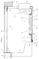
- Cross members (2) serve as the machine foundation.
- the Hall floor is shown at (3).
- a floor is delimited by the continuous longitudinal member (4) in which the drive machines are accommodated.
- the side boundaries are indicated at (5) and by arrow (6).
- the motor terminal box (7) is partially drawn with dash-dotted lines.
- the basement (8) is limited on the system side by supporting scaffolding (9) on which the longitudinal member (4) rests. This is followed by a basement ceiling, generally designated (10), which covers the noise-filled room (12) with vertical soundproof walls (11).
- the soundproof walls (11) have openings secured with silencers (13).
- the machines in room (12) are accessible from the basement (8).
- the ceiling is divided into a number of soundproofing elements.
- the soundproofing elements (14 and 15) are stationary on both sides of a cellar opening (18).
- the cellar opening (18) can be closed with movable soundproofing elements, which are generally shown at (16 and 17) in Fig. 1.
- the soundproofing elements (16) are slidably arranged in an upper horizontal plane (19).
- the soundproofing elements (17) are aligned under the soundproofing elements (16) in a further horizontal plane (20).
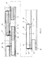
- Each of the soundproofing elements has a closed box made of a possibly closed or perforated cover plate (21) (FIG. 3), a likewise closed or perforated base plate (22), vertical end plates (23, 24) and vertical longitudinal plates (25, 26) on.
- the interior is filled with mineral fiber or wool mats, as shown schematically at (27) in Fig. 2.
- the soundproofing elements (16, 17) have the same floor plans and can be moved on a double track (28).
- the double track has an upper pair of rails (29, 30), while the lower track has a pair of rails (31, 32).
- This pair of rails consists of an angle profile.
- the horizontal angle leg (33) supports the associated side of the soundproofing element in question, while the vertical leg (34) serves for lateral guidance of the soundproofing element on the side in question. With their openings, the angle profiles are oriented towards the middle of the track.
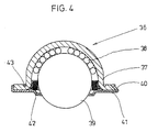
- such a supporting ball roller arrangement (36) consists of a spherical ball cage (37) in which rolling elements (38) support the supporting ball (39).
- a bearing plate (41) bent at its edges at (40) serves to hold the support ball, and the rolling elements (38) are closed off to the outside with an annular seal (42).
- An annular groove (43) surrounding the dome edge serves to center the ball bearing cage in a bearing plate (44) on the inside of the base plate (22).
- the soundproofing elements In addition to the supporting ball rollers (36), which are attached in pairs, as shown at (44 and 45) in Fig. 3, on the front and rear on both sides of the movable soundproofing element 16 and 17), the soundproofing elements have pressure ball rollers (46, 47) on each side with which they are supported on the vertical angle legs (34) of the tracks.
- the structure of these pressure ball rollers (46, 47) corresponds to the support ball rollers (36) shown in FIG. 4 and described above, which are supported on the horizontal angle legs via the supports (35).
- Hollow seals (54) are attached to the longitudinal edges (53) of the supports (35) directed towards the middle of the track and on the inner ends of the horizontal angle legs. These seals have clamping bands (55), which encompass the free edges of the horizontal angle legs, and sealing elements (56) made of soft or cellular rubber and formed integrally with the clamping bands, the upper sides (57) of which seal on the base plates (22) as soon as the idlers (36) has fallen into one of the depressions (50), the sealing pressure being generated by the weight of the soundproofing element (16, 17) in question.
- Each of the soundproofing elements (16) has on its vertical end faces (23, 24) attached buffer strips (58, 59) to which sealing tabs (60, 61) are attached are.
- the sealing flaps (60, 61) are only attached to the soundproofing elements (16), but can be deflected by cover plates (21) of the soundproofing elements (17) and then also seal on the cover plates.
- FIG. 3 shows the position of the movable soundproofing elements (16, 17) which they occupy when the soundproofing cover (18) is closed.
- successive and superimposed soundproofing elements (16, 17) such as the example of the movable soundproofing elements designated in Fig. 3 with (63-66), form a cross structure in which the upper vertical joint (67) with the lower soundproofing element ( 66) is covered, while the horizontal joint (68) is sealed with the deflected sealing tabs (60 and 61) of the elements (63 and 65). Since in this closed position the support rollers (36) of all the elements are located in the recesses (50) assigned to them, the soft seals (56) with their sealing surfaces (57) lie against the relevant floor panels of the soundproofing elements (63-65).
- each Soundproofing element forms the rotor of two layers, which are arranged in the levels (19 and 20).
- the soundproofing elements (16 and 17) can be pushed together anywhere on the basement ceiling (18) on one or both sides of the tracks (29-32) until the end faces (23, 24) or the buffers (58 , 59) lie on top of each other. Then the vertical joints (67) are closed, while the support rollers (36) have left the depressions (50) via one of the oblique flanks (51, 52), whereby the sealing pressure of the flexible seals (56) is released at the same time.
- the horizontal assignment then achieved is shown in FIG. 3 using the soundproofing elements (69 and 70).
- the double track (71) with its lower track is shifted to horizontal beams (73) which are attached to the vertical soundproof walls (11) at predetermined intervals.
- the brackets (73) are supported on sound-insulating buffers (75) via angle plates (74) which are open at the bottom and which in turn are supported on angle profiles (76) of the continuous longitudinal member (4) which are open towards the center.
- the sound-insulating buffers (77) are also between the soundproof walls (11) and the upper beams (78) of the hall floor.
- the stationary soundproofing elements (14, 15) should have closed cover plates in order to keep the oil coming from the machines away from the mineral wool filling.
Landscapes
- Engineering & Computer Science (AREA)
- Mechanical Engineering (AREA)
- Building Environments (AREA)
- Soil Working Implements (AREA)
- Buildings Adapted To Withstand Abnormal External Influences (AREA)
- Branching, Merging, And Special Transfer Between Conveyors (AREA)
Priority Applications (1)
| Application Number | Priority Date | Filing Date | Title |
|---|---|---|---|
| AT88100207T ATE90028T1 (de) | 1987-12-21 | 1988-01-09 | Anordnung zur kapselung langgestreckter anlagen mit seitlichem maschinenkeller. |
Applications Claiming Priority (2)
| Application Number | Priority Date | Filing Date | Title |
|---|---|---|---|
| DE3743370 | 1987-12-21 | ||
| DE3743370 | 1987-12-21 |
Publications (3)
| Publication Number | Publication Date |
|---|---|
| EP0321632A2 EP0321632A2 (de) | 1989-06-28 |
| EP0321632A3 EP0321632A3 (en) | 1990-02-28 |
| EP0321632B1 true EP0321632B1 (de) | 1993-06-02 |
Family
ID=6343170
Family Applications (1)
| Application Number | Title | Priority Date | Filing Date |
|---|---|---|---|
| EP88100207A Expired - Lifetime EP0321632B1 (de) | 1987-12-21 | 1988-01-09 | Anordnung zur Kapselung langgestreckter Anlagen mit seitlichem Maschinenkeller |
Country Status (4)
| Country | Link |
|---|---|
| EP (1) | EP0321632B1 (es) |
| AT (1) | ATE90028T1 (es) |
| DE (1) | DE3881494D1 (es) |
| ES (1) | ES2041273T3 (es) |
Families Citing this family (1)
| Publication number | Priority date | Publication date | Assignee | Title |
|---|---|---|---|---|
| US5865119A (en) * | 1995-03-18 | 1999-02-02 | Koenig & Bauer-Albert Aktiengesellschaft | Soundproofing |
Family Cites Families (4)
| Publication number | Priority date | Publication date | Assignee | Title |
|---|---|---|---|---|
| US1886762A (en) * | 1930-01-04 | 1932-11-08 | Wood Newspaper Mach Corp | Printing press structure |
| US2133459A (en) * | 1935-08-24 | 1938-10-18 | Stanley D Livingston | Printing press |
| DE1153282B (de) * | 1955-05-05 | 1963-08-22 | Mac Gregor & Co Naval Architec | Lukenverschlussvorrichtung fuer Schiffsluken |
| FR1285204A (fr) * | 1955-05-05 | 1962-02-23 | Dispositif de commande de panneaux d'écoutille |
-
1988
- 1988-01-09 ES ES198888100207T patent/ES2041273T3/es not_active Expired - Lifetime
- 1988-01-09 DE DE8888100207T patent/DE3881494D1/de not_active Expired - Fee Related
- 1988-01-09 EP EP88100207A patent/EP0321632B1/de not_active Expired - Lifetime
- 1988-01-09 AT AT88100207T patent/ATE90028T1/de not_active IP Right Cessation
Also Published As
| Publication number | Publication date |
|---|---|
| EP0321632A3 (en) | 1990-02-28 |
| EP0321632A2 (de) | 1989-06-28 |
| DE3881494D1 (de) | 1993-07-08 |
| ES2041273T3 (es) | 1993-11-16 |
| ATE90028T1 (de) | 1993-06-15 |
Similar Documents
| Publication | Publication Date | Title |
|---|---|---|
| EP0803320B1 (de) | Werkzeugmaschine mit einer Lamellentüre | |
| DE2400313A1 (de) | Hilfseinrichtung fuer einen seilnetzkuehlturm | |
| EP0321632B1 (de) | Anordnung zur Kapselung langgestreckter Anlagen mit seitlichem Maschinenkeller | |
| DE69229062T2 (de) | Vorrichtung zum kontrollieren von vertikalen Vibrationen | |
| DE3714053C2 (de) | Aufzug für Personentransport | |
| EP0054918A1 (de) | Vorrichtung für die Einführung von Installationsrohren und -leitungen in unterkellerte Gebäude | |
| DE102008038409A1 (de) | Kabinentürschürze (Einroll-Mechanismus) | |
| EP2910682A1 (de) | Flächige schallschutzkonstruktion | |
| DE4317528A1 (de) | Hubanlage für Schienenfahrzeuge | |
| EP1503827B1 (de) | Schott zur abdichtung eines tunnels im brandfall | |
| DE102011013145B4 (de) | Modulare schwenkbare niedrige Schallschutzwand | |
| DE9418619U1 (de) | Arbeitskabine | |
| DE19837695C2 (de) | Verfahren zum Herstellen einer Lüftungs- und/oder Entrauchungsdecke in einer tunnelförmigen Verkehrsanlage und Modul hierfür | |
| DE10142783A1 (de) | Lagerung zum Lagern von speziellen Gleiskonstruktionen | |
| DE19915367A1 (de) | Anordnung und Verfahren zur Erstellung einer temporären Schutzüberdachung | |
| AT520960B1 (de) | Staubschutzwand | |
| DE8909520U1 (de) | Vorrichtung zum Schutz von auf dem Boden verlegten Installationsleitungen | |
| DE202006020434U1 (de) | Schutzvorrichtung für ein bestehendes, ortsfestes Objekt oder Bauwerk | |
| DE7223445U (de) | Schaltanlage | |
| DE2459240C2 (de) | Winterbaudach | |
| DE19826165C1 (de) | System zum Abdichten von Räumen | |
| DE4210248A1 (de) | Explosionsgeschützte Stahlbetonraumzelle, insbesondere Stahlbetonraumzellentrafostation | |
| AT409017B (de) | Mobiles veranstaltungszentrum | |
| DE19843030A1 (de) | Baugerüst | |
| DE2801695B2 (de) | Abschottung für einen Streckenabschnitt einer Tunnelröhre |
Legal Events
| Date | Code | Title | Description |
|---|---|---|---|
| PUAI | Public reference made under article 153(3) epc to a published international application that has entered the european phase |
Free format text: ORIGINAL CODE: 0009012 |
|
| AK | Designated contracting states |
Kind code of ref document: A2 Designated state(s): AT BE CH DE ES FR GB IT LI LU NL SE |
|
| 17P | Request for examination filed |
Effective date: 19890719 |
|
| PUAL | Search report despatched |
Free format text: ORIGINAL CODE: 0009013 |
|
| AK | Designated contracting states |
Kind code of ref document: A3 Designated state(s): AT BE CH DE ES FR GB IT LI LU NL SE |
|
| 17Q | First examination report despatched |
Effective date: 19920428 |
|
| GRAA | (expected) grant |
Free format text: ORIGINAL CODE: 0009210 |
|
| AK | Designated contracting states |
Kind code of ref document: B1 Designated state(s): AT BE CH DE ES FR GB IT LI LU NL SE |
|
| REF | Corresponds to: |
Ref document number: 90028 Country of ref document: AT Date of ref document: 19930615 Kind code of ref document: T |
|
| REF | Corresponds to: |
Ref document number: 3881494 Country of ref document: DE Date of ref document: 19930708 |
|
| ET | Fr: translation filed | ||
| GBT | Gb: translation of ep patent filed (gb section 77(6)(a)/1977) |
Effective date: 19930622 |
|
| ITF | It: translation for a ep patent filed | ||
| REG | Reference to a national code |
Ref country code: ES Ref legal event code: FG2A Ref document number: 2041273 Country of ref document: ES Kind code of ref document: T3 |
|
| PGFP | Annual fee paid to national office [announced via postgrant information from national office to epo] |
Ref country code: FR Payment date: 19931217 Year of fee payment: 7 |
|
| PGFP | Annual fee paid to national office [announced via postgrant information from national office to epo] |
Ref country code: GB Payment date: 19931220 Year of fee payment: 7 |
|
| PGFP | Annual fee paid to national office [announced via postgrant information from national office to epo] |
Ref country code: ES Payment date: 19940124 Year of fee payment: 7 |
|
| PGFP | Annual fee paid to national office [announced via postgrant information from national office to epo] |
Ref country code: SE Payment date: 19940125 Year of fee payment: 7 Ref country code: AT Payment date: 19940125 Year of fee payment: 7 |
|
| PGFP | Annual fee paid to national office [announced via postgrant information from national office to epo] |
Ref country code: NL Payment date: 19940131 Year of fee payment: 7 Ref country code: LU Payment date: 19940131 Year of fee payment: 7 |
|
| PGFP | Annual fee paid to national office [announced via postgrant information from national office to epo] |
Ref country code: BE Payment date: 19940207 Year of fee payment: 7 |
|
| PGFP | Annual fee paid to national office [announced via postgrant information from national office to epo] |
Ref country code: CH Payment date: 19940216 Year of fee payment: 7 |
|
| EPTA | Lu: last paid annual fee | ||
| PGFP | Annual fee paid to national office [announced via postgrant information from national office to epo] |
Ref country code: DE Payment date: 19940329 Year of fee payment: 7 |
|
| PLBE | No opposition filed within time limit |
Free format text: ORIGINAL CODE: 0009261 |
|
| STAA | Information on the status of an ep patent application or granted ep patent |
Free format text: STATUS: NO OPPOSITION FILED WITHIN TIME LIMIT |
|
| 26N | No opposition filed | ||
| PG25 | Lapsed in a contracting state [announced via postgrant information from national office to epo] |
Ref country code: LU Free format text: LAPSE BECAUSE OF NON-PAYMENT OF DUE FEES Effective date: 19950109 Ref country code: GB Effective date: 19950109 Ref country code: AT Effective date: 19950109 |
|
| PG25 | Lapsed in a contracting state [announced via postgrant information from national office to epo] |
Ref country code: SE Effective date: 19950110 Ref country code: ES Free format text: LAPSE BECAUSE OF NON-PAYMENT OF DUE FEES Effective date: 19950110 |
|
| EAL | Se: european patent in force in sweden |
Ref document number: 88100207.5 |
|
| PG25 | Lapsed in a contracting state [announced via postgrant information from national office to epo] |
Ref country code: LI Effective date: 19950131 Ref country code: CH Effective date: 19950131 Ref country code: BE Effective date: 19950131 |
|
| BERE | Be: lapsed |
Owner name: ANTIBEL G.- FUR SCHALLSCHUTZ M.B.H. Effective date: 19950131 |
|
| PG25 | Lapsed in a contracting state [announced via postgrant information from national office to epo] |
Ref country code: NL Effective date: 19950801 |
|
| GBPC | Gb: european patent ceased through non-payment of renewal fee |
Effective date: 19950109 |
|
| PG25 | Lapsed in a contracting state [announced via postgrant information from national office to epo] |
Ref country code: FR Effective date: 19950929 |
|
| REG | Reference to a national code |
Ref country code: CH Ref legal event code: PL |
|
| NLV4 | Nl: lapsed or anulled due to non-payment of the annual fee |
Effective date: 19950801 |
|
| PG25 | Lapsed in a contracting state [announced via postgrant information from national office to epo] |
Ref country code: DE Effective date: 19951003 |
|
| EUG | Se: european patent has lapsed |
Ref document number: 88100207.5 |
|
| REG | Reference to a national code |
Ref country code: FR Ref legal event code: ST |
|
| REG | Reference to a national code |
Ref country code: ES Ref legal event code: FD2A Effective date: 19990301 |
|
| PG25 | Lapsed in a contracting state [announced via postgrant information from national office to epo] |
Ref country code: IT Free format text: LAPSE BECAUSE OF NON-PAYMENT OF DUE FEES Effective date: 20050109 |