EP0321279A1 - Spender - Google Patents
Spender Download PDFInfo
- Publication number
- EP0321279A1 EP0321279A1 EP88311938A EP88311938A EP0321279A1 EP 0321279 A1 EP0321279 A1 EP 0321279A1 EP 88311938 A EP88311938 A EP 88311938A EP 88311938 A EP88311938 A EP 88311938A EP 0321279 A1 EP0321279 A1 EP 0321279A1
- Authority
- EP
- European Patent Office
- Prior art keywords
- wall
- bag
- parts
- hole
- piston
- Prior art date
- Legal status (The legal status is an assumption and is not a legal conclusion. Google has not performed a legal analysis and makes no representation as to the accuracy of the status listed.)
- Granted
Links
Images


Classifications
-
- A—HUMAN NECESSITIES
- A47—FURNITURE; DOMESTIC ARTICLES OR APPLIANCES; COFFEE MILLS; SPICE MILLS; SUCTION CLEANERS IN GENERAL
- A47K—SANITARY EQUIPMENT; ACCESSORIES THEREFOR, e.g. TOILET ACCESSORIES
- A47K5/00—Holders or dispensers for soap, toothpaste or the like
- A47K5/06—Dispensers for soap
- A47K5/12—Dispensers for soap for liquid or pasty soap
- A47K5/1202—Dispensers for soap for liquid or pasty soap dispensing dosed volume
- A47K5/1208—Dispensers for soap for liquid or pasty soap dispensing dosed volume by means of a flexible dispensing chamber
-
- A—HUMAN NECESSITIES
- A47—FURNITURE; DOMESTIC ARTICLES OR APPLIANCES; COFFEE MILLS; SPICE MILLS; SUCTION CLEANERS IN GENERAL
- A47K—SANITARY EQUIPMENT; ACCESSORIES THEREFOR, e.g. TOILET ACCESSORIES
- A47K5/00—Holders or dispensers for soap, toothpaste or the like
- A47K5/06—Dispensers for soap
- A47K5/12—Dispensers for soap for liquid or pasty soap
- A47K5/122—Dispensers for soap for liquid or pasty soap using squeeze bottles or the like
Definitions
- This invention relates to dispensing devices for liquids such as liquid hand soap, and of the type comprising a flexible plastic bag containing the liquid and having a lower end portion formed by mutually opposite front and back walls.
- the back wall has a hole in which a self-closing metering valve is sealed.
- This valve comprises a tubular part which extends through the hole in the bag wall, with its outer end normally closed by a self-closing valve. The upper end of this part is open to the inside of the bag but closed by an elastically deflective dome having a hole through which liquid in the bag can enter and fill the space between the inside of the dome and the self-closing valve. The dome is completely on the inside of the bag walls.
- the bag is normally hung by its top against the back wall of a cabinet having a forwardly projecting shelf, the bottom or lower portion of the bag being folded forwardly so as to form upper and lower walls, and supported on this shelf with a portion of its valve extending downwardly through the hole in the shelf.
- Each finger pressure on the upper bag wall causes the liquid to be dispensed in the form of shots each metered in volume by the volume of the space beneath the dome and self-closing valve.
- An advantage of a preferred embodiment of the present invention is achieved by providing a device of the type described with the actuating dome positioned completely outside of the bag through the upper bag wall, and free from the hole in the top of the dome.
- the present invention provides a dispensing device for a bag made of flexible material and forming upper and lower walls through which mutually registered holes are formed for receiving the device, the device comprising a tubular lower part having a top forming an outward flange which is sealed to the inside of the lower wall with the lower part depending through the hole in the lower wall, and a tubular upper part having a top forming an outwardly flange which is sealed to the inside of the upper wall and depending through the hole in the upper wall and telescoped inside the lower part and movable up and down therein, the top of the upper part forming a piston closing the top and accessible on the outside of the upper wall, spring means for elastically biasing the parts apart from each other so that normally there is a space between the flanges, the lower part having a lower end and a self-closing valve normally closing the lower end of the lower part, the lower part having at least one side port normally open to said space so that liquid in the bag can flow into the parts, movement of the upper part into the lower
- the upper and lower parts each comprise a plastic molding.
- the device has a spider which has a ring positioned between said parts and said spring means comprises an annular series of leafsprings formed by the ring of the spider and which bear against the bottom periphery of the upper part.
- the spring means comprises an annular series of springs formed by the flange of one of said parts and which bear against the flange of the other said parts.
- the piston is in the form of an elastically collapsible dome closing the top of said upper part and extending upwardly through the hole in the upper wall and exposed on the outside of the upper wall.
- the piston is in the form of a rigid wall substantially on the same level as the top of the upper tubular part and which is rigidly connected to the top of the upper part.
- applicant's new device requires both the upper and lower walls of the forwardly folded lower bag portion, to be formed with holes which mutually register.
- the device has a lower tubular part depending through the hole in the lower bag wall and an outward flange on its top which is sealed to the inside of the lower wall, and an upper tubular part having a top forming a piston which is accesible upwardly through the hole in the upper bag wall and outside of the upper bag wall.
- This upper part has an outer flange which is sealed to the inside of the upper bag wall and from which depends a tubular part which is slidingly telescoped inside of the lower part of the device.
- the two bag walls keep the lower and upper parts from completely separating.
- the lower part has its outer or bottom end closed by a self-closing valve.
- a spring arrangement elastically biases the lower and upper parts of the device normally separated so that there is a space between the opposing flanges of the parts, and the upper part has a circumferencial series of ports through which liquid can flow to the inside of the device through the space between the two flanges, to between the dome and self-closing valve of the device.
- the actuator dome or piston
- the dome or piston is free from the prior art hole requiring closure by the finger of the person actuating the device.
- the dome or piston is pressed downwardly until the upper part telescopes down into the lower part so that the flanges of the two parts intercontact and seal off the inside of the device from the inside of the bag containing the liquid.
- the dome or piston now causes pressure on the liquid trapped inside the device, so that the self-closing valve is forced open and dispensing of the liquid occurs.
- the amount of liquid dispensed for each operation of the device is determined by the volume of the interior of the device between the dome or piston and the self-closing valve.
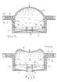
- the cabinet shown by Figures 1 and 2 has a back wall 1 which is vertical and ordinarily fastened to a vertical wall, and a forwardly projecting shelf 2 having the hole 3.
- Fig. 2 the cabinet cover is removed, and the bag 4 formed by flexible front and back walls and having its lower portion folded forwardly is about to be laid on the shelf 2 with the bag's dispensing device having its downwardly lower part about to be inserted in the hole 3.
- the bag is made from very flexible plastic sheets side seemed together hermetically and containing the liquid to be dispensed such as liquid soap.
- the lower tubular part 5 of the device is formed with a rib 5a and the hole 3 is formed with a groove 3a, insuring that only appropriate bags are used with the cabinet.
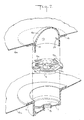
- the lower part 5 of the device is preferably cylindrical and has an inner end with an external flange 6 for sealing to the inside of the lower bag wall 4a.
- This tubular body of the lower part 5 extends downwardly for insertion in the hole 3 of the cabinet and its bottom end supports an elastically deflective diaphragm 7 having a discharge opening forming a valve seat 8.
- a valve head 9 is stationary and supported above the valve seat 8 by a spider 9 having a periphery snapped in a groove on the inside of the part 5.
- the valve seat 8 is normally pressed against the valve head 9 by the elasticity of the diaphragm 7, liquid under pressure on the top of this diaphragm causing it to move downwardly and open the valve seat 8 from the valve head 9.
- the device includes an upper part formed by a tubular or cylindrical body 12 having an upper flange 14 which is sealed to the inside of the upper wall of the bags forwardly folded bottom portion.
- the tubular body 12 of the upper part 13 is telescoped inside of the tubular body of the lower part and can slide up and down in the lower part.
- the spider 9 is formed with an annular series of upward acting springs 9a which bear against the bottom periphery of the upper part 13 and keep it elastically biased upwardly.
- the two parts of the valve cannot completely separate because of the restraint offered by the bag walls 4a and 4b.
- the tubular body 12 of the upper part has a circumferential series of ports 15 which registered with the space between the separated flanges 6 and 14, and liquid in the bag can flow through these ports to the inside of the upper and lower parts of the device.
- the upper part from its flange 14 upwardly has the elastically deflective dome 16 which is free from the top hole of the prior art devices.
- the dome 16 is initially pressed downwardly, the entire upper part moving downwardly so that the flanges 6 and 14 press together and fluid-tightly trap the liquid that flowed into the device initially.
- the bottom 12a of the upper part's body 13 completely collapses the springs 9a and solidly engages a periphery of the spider 9, as shown by Fig. 5.
- Continued pressure on the dome causes it to collapse and pressurize the liquid trapped in the device so that the liquid presses the diaphragm 7 of the self-closing valve downwardly, so that discharge is effected as shown by Fig. 6.
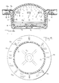
- Figs. 12 and 13 uses the rigid type of piston.
- tubular part 5a of the lower part and the tubular part 12a of the upper part are lengthened and the springs 9b extended more upwardly so that the upper part can move through a much longer distance than before relative to the lower part.
- the posts 15a are positioned so as to be closed by the tubular post 15a so that liquid in the devise is locked against reverse flow soon after initial downward displacement of the upper part. This locking occurs whether or not the flanges 6a and 14a interengage.
- the top of the upper tubular part is closed by a solid rigid wall 16a. If the upper part is plastic this wall may be integral with the tubular part and rigidfied by ribs 16b. This flat top can be on the same level or close thereto as the balance of the upper part but exposed to the outside of the upper bag wall.
- the advantage is that the flat rigid top does not provide space below its bottom for the collection of air which might interfere with the desired operation of the device.
Landscapes
- Health & Medical Sciences (AREA)
- Public Health (AREA)
- Containers And Packaging Bodies Having A Special Means To Remove Contents (AREA)
- Closures For Containers (AREA)
Priority Applications (1)
| Application Number | Priority Date | Filing Date | Title |
|---|---|---|---|
| AT88311938T ATE72950T1 (de) | 1987-12-18 | 1988-12-16 | Spender. |
Applications Claiming Priority (2)
| Application Number | Priority Date | Filing Date | Title |
|---|---|---|---|
| US134703 | 1987-12-18 | ||
| US07/134,703 US4823990A (en) | 1987-12-18 | 1987-12-18 | Dispensing device |
Publications (2)
| Publication Number | Publication Date |
|---|---|
| EP0321279A1 true EP0321279A1 (de) | 1989-06-21 |
| EP0321279B1 EP0321279B1 (de) | 1992-03-04 |
Family
ID=22464586
Family Applications (1)
| Application Number | Title | Priority Date | Filing Date |
|---|---|---|---|
| EP88311938A Expired - Lifetime EP0321279B1 (de) | 1987-12-18 | 1988-12-16 | Spender |
Country Status (10)
| Country | Link |
|---|---|
| US (1) | US4823990A (de) |
| EP (1) | EP0321279B1 (de) |
| JP (1) | JPH02305528A (de) |
| KR (1) | KR970009252B1 (de) |
| AR (1) | AR243462A1 (de) |
| AT (1) | ATE72950T1 (de) |
| AU (1) | AU601891B2 (de) |
| BR (1) | BR8806699A (de) |
| DE (1) | DE3868888D1 (de) |
| MX (1) | MX165669B (de) |
Cited By (5)
| Publication number | Priority date | Publication date | Assignee | Title |
|---|---|---|---|---|
| EP0452260A3 (en) * | 1990-04-09 | 1992-03-04 | Compagnie Francaise Des Matieres Plastiques Plasco | Pumping device for a fluid product, particularly liquid or pasty, and dispenser for such a device |
| US5273186A (en) * | 1991-07-04 | 1993-12-28 | Unilever Patent Holdings B.V. | Dispensing device for liquid detergent |
| US6183765B1 (en) | 1996-05-28 | 2001-02-06 | Bayer Aktiengesellschaft | Silicon elastomers with insecticidal effect |
| EP1247483A1 (de) * | 2001-04-02 | 2002-10-09 | Green Power S.a.s. di Martinelli Adriano e C. | Zubehör für Geschirrspülmaschine |
| KR100502224B1 (ko) * | 1999-09-16 | 2005-07-19 | 칸퍼 조셉 에스. | 소형 유체 펌프 |
Families Citing this family (22)
| Publication number | Priority date | Publication date | Assignee | Title |
|---|---|---|---|---|
| US4921136A (en) * | 1988-11-29 | 1990-05-01 | Inopak Ltd. | Fixture for bag-type liquid dispenser |
| US5207355A (en) * | 1991-12-30 | 1993-05-04 | Thomsen Peter N | High viscosity pump system for dispenser pouch |
| US7331944B2 (en) | 2000-10-23 | 2008-02-19 | Medical Instill Technologies, Inc. | Ophthalmic dispenser and associated method |
| KR100865601B1 (ko) | 2000-10-23 | 2008-10-27 | 피 페턴트, 인크. | 유체 분배기 및 유체 분배기 충진 방법 |
| US6767194B2 (en) * | 2001-01-08 | 2004-07-27 | President And Fellows Of Harvard College | Valves and pumps for microfluidic systems and method for making microfluidic systems |
| FR2821339B1 (fr) * | 2001-02-28 | 2003-08-01 | Airlessystems | Distributeur de produit fluide a poche souple et procede de fabrication d'une telle poche souple |
| US7798185B2 (en) | 2005-08-01 | 2010-09-21 | Medical Instill Technologies, Inc. | Dispenser and method for storing and dispensing sterile food product |
| EP1546021B1 (de) | 2002-08-13 | 2010-10-20 | Medical Instill Technologies, Inc. | Behälter und ventilanordnung zum lagern und abgeben von substanzen und verwandtes verfahren |
| EP1636091A2 (de) | 2003-05-12 | 2006-03-22 | Medical Instill Technologies, Inc. | Abgabevorrichtung und vorrichtung zum füllen einer abgabevorrichtung |
| US7226231B2 (en) | 2003-07-17 | 2007-06-05 | Medical Instill Technologies, Inc. | Piston-type dispenser with one-way valve for storing and dispensing metered amounts of substances |
| US7264142B2 (en) | 2004-01-27 | 2007-09-04 | Medical Instill Technologies, Inc. | Dispenser having variable-volume storage chamber and depressible one-way valve assembly for dispensing creams and other substances |
| US8061566B2 (en) * | 2007-04-26 | 2011-11-22 | Sealed Air Corporation (Us) | Metering dispensing system with improved valving to prevent accidental dispensing of liquid therefrom |
| US7810677B2 (en) * | 2004-12-04 | 2010-10-12 | Medical Instill Technologies, Inc. | One-way valve and apparatus and method of using the valve |
| AU2005314177B2 (en) * | 2004-12-04 | 2010-10-28 | Medical Instill Technologies, Inc. | One-way valve, apparatus and method of using the valve |
| BRPI0706436A2 (pt) * | 2006-01-05 | 2011-03-29 | Medical Instill Tech Inc | válvula unidirecional e aparelho e método de uso da mesma |
| JP4717714B2 (ja) * | 2006-05-17 | 2011-07-06 | 株式会社三栄水栓製作所 | 液体石鹸用ディスペンサー |
| US8356733B2 (en) * | 2006-09-08 | 2013-01-22 | Medical Instill Technologies, Inc. | Method for dispensing fluids |
| US9358539B2 (en) * | 2008-05-16 | 2016-06-07 | President And Fellows Of Harvard College | Valves and other flow control in fluidic systems including microfluidic systems |
| JP5774681B2 (ja) | 2010-05-07 | 2015-09-09 | エーエルピーエス エルエルシー | 吐出装置用の弁及び方法 |
| FR3020051B1 (fr) * | 2014-04-16 | 2016-05-13 | Aptar France Sas | Distributeur de produit fluide. |
| JP6780988B2 (ja) * | 2016-09-08 | 2020-11-04 | 旭化成パックス株式会社 | 定量吐出装置、複合体、及び組立体 |
| KR102279706B1 (ko) | 2020-12-17 | 2021-07-20 | 주식회사 해섬 | 생선 절단 장치 |
Citations (2)
| Publication number | Priority date | Publication date | Assignee | Title |
|---|---|---|---|---|
| US4570827A (en) * | 1984-03-28 | 1986-02-18 | Essex Chemical Corp. | Liquid dispenser |
| EP0207279A1 (de) * | 1985-05-28 | 1987-01-07 | Essex Chemical Corporation | Befestigung für einen Flüssigkeitsspender des Beuteltyps |
Family Cites Families (9)
| Publication number | Priority date | Publication date | Assignee | Title |
|---|---|---|---|---|
| US2093942A (en) * | 1935-04-09 | 1937-09-21 | Michael J Stuff | Dispenser |
| CH539807A (fr) * | 1971-07-06 | 1973-07-31 | Zyma Sa | Soupape-doseuse |
| FR2204799B1 (de) * | 1972-10-31 | 1978-12-29 | Gournelle Maurice | |
| US3885709A (en) * | 1974-02-01 | 1975-05-27 | Varian Associates | Liquid toner concentrate dispenser having a valve responsive to hydrostatic pressure |
| US4238056A (en) * | 1978-03-06 | 1980-12-09 | Towlsaver, Inc. | Soap dispenser having a pivotable dispensing lever and a rotatable flow valve |
| US4226342A (en) * | 1978-12-15 | 1980-10-07 | Laauwe Robert H | Dispensing valve particularly for viscous products |
| CA1174650A (en) * | 1981-03-24 | 1984-09-18 | Ronald L. Whipperman | Apparatus and method for dispensing liquid soap |
| US4478356A (en) * | 1982-06-24 | 1984-10-23 | Essex Chemical Corporation | Flexible-bag self-closing metering dispensing valve |
| US4506809A (en) * | 1982-06-25 | 1985-03-26 | Calmar, Inc. | Dispensing fitment for squeeze bottles |
-
1987
- 1987-12-18 US US07/134,703 patent/US4823990A/en not_active Expired - Lifetime
-
1988
- 1988-12-15 AU AU26912/88A patent/AU601891B2/en not_active Ceased
- 1988-12-16 AT AT88311938T patent/ATE72950T1/de not_active IP Right Cessation
- 1988-12-16 BR BR888806699A patent/BR8806699A/pt unknown
- 1988-12-16 AR AR88312761A patent/AR243462A1/es active
- 1988-12-16 MX MX014216A patent/MX165669B/es unknown
- 1988-12-16 DE DE8888311938T patent/DE3868888D1/de not_active Expired - Fee Related
- 1988-12-16 EP EP88311938A patent/EP0321279B1/de not_active Expired - Lifetime
- 1988-12-17 KR KR1019880016908A patent/KR970009252B1/ko not_active Expired - Lifetime
- 1988-12-19 JP JP63320340A patent/JPH02305528A/ja active Pending
Patent Citations (2)
| Publication number | Priority date | Publication date | Assignee | Title |
|---|---|---|---|---|
| US4570827A (en) * | 1984-03-28 | 1986-02-18 | Essex Chemical Corp. | Liquid dispenser |
| EP0207279A1 (de) * | 1985-05-28 | 1987-01-07 | Essex Chemical Corporation | Befestigung für einen Flüssigkeitsspender des Beuteltyps |
Cited By (6)
| Publication number | Priority date | Publication date | Assignee | Title |
|---|---|---|---|---|
| EP0452260A3 (en) * | 1990-04-09 | 1992-03-04 | Compagnie Francaise Des Matieres Plastiques Plasco | Pumping device for a fluid product, particularly liquid or pasty, and dispenser for such a device |
| US5197637A (en) * | 1990-04-09 | 1993-03-30 | Compagnie Francaise Des Matieres Plastiques Plasco | Pump apparatus for a free-flowing, in particular pasty and/or liquid, product, and dispenser having such a pump apparatus |
| US5273186A (en) * | 1991-07-04 | 1993-12-28 | Unilever Patent Holdings B.V. | Dispensing device for liquid detergent |
| US6183765B1 (en) | 1996-05-28 | 2001-02-06 | Bayer Aktiengesellschaft | Silicon elastomers with insecticidal effect |
| KR100502224B1 (ko) * | 1999-09-16 | 2005-07-19 | 칸퍼 조셉 에스. | 소형 유체 펌프 |
| EP1247483A1 (de) * | 2001-04-02 | 2002-10-09 | Green Power S.a.s. di Martinelli Adriano e C. | Zubehör für Geschirrspülmaschine |
Also Published As
| Publication number | Publication date |
|---|---|
| BR8806699A (pt) | 1989-08-29 |
| AU601891B2 (en) | 1990-09-20 |
| JPH02305528A (ja) | 1990-12-19 |
| KR890009347A (ko) | 1989-08-01 |
| MX165669B (es) | 1992-11-27 |
| KR970009252B1 (ko) | 1997-06-09 |
| ATE72950T1 (de) | 1992-03-15 |
| DE3868888D1 (de) | 1992-04-09 |
| EP0321279B1 (de) | 1992-03-04 |
| AR243462A1 (es) | 1993-08-31 |
| US4823990A (en) | 1989-04-25 |
| AU2691288A (en) | 1989-06-22 |
Similar Documents
| Publication | Publication Date | Title |
|---|---|---|
| EP0321279B1 (de) | Spender | |
| US8113239B2 (en) | Vented valve assembly | |
| EP1371579B1 (de) | Ventilmechanismus für Flüssigkeitsbehälter | |
| RU2277501C2 (ru) | Устройство для расфасовки и дозирования вещества, в частности в виде косметического средства | |
| KR100898619B1 (ko) | 유체 펌핑장치 | |
| KR100569180B1 (ko) | 소형 수동식 펌프 | |
| US5031802A (en) | Metering bottle | |
| US7059499B2 (en) | Fluid-dispensing pump and container provided therewith | |
| EP0253577A2 (de) | Pumpenkammer-Spender | |
| WO2013022634A2 (en) | Split body pumps for foam dispensers and refill units | |
| US4533069A (en) | Pump-type dispenser | |
| KR101907778B1 (ko) | 이종물질혼합용기 | |
| JPH1072052A (ja) | 液体注出器 | |
| JP2019135172A (ja) | 流体容器 | |
| KR102424147B1 (ko) | 펌핑식 용기용 스프링 및 이를 포함하는 펌핑식 용기 | |
| KR200412917Y1 (ko) | 컵 겸용 버튼이 구비된 디스펜서 | |
| US5894961A (en) | Dispenser with resilient reservoir structure | |
| JP3369699B2 (ja) | 注出容器 | |
| WO2009008675A1 (en) | Fluid pumping apparatus | |
| KR102642103B1 (ko) | 액상-페이스트상 제품을 분배하기 위한 장치 및 이를 위한 모듈 형성 폐쇄 장치 | |
| KR102731392B1 (ko) | 거품 토출형 디스펜서 | |
| KR102708530B1 (ko) | 펌핑형 용기 | |
| KR102938545B1 (ko) | 잔량소진이 가능한 에어리스 디스펜서 | |
| KR102780668B1 (ko) | Pp소재의 화장품용 에어리스 디스펜서 | |
| KR200498226Y1 (ko) | 펌핑형 용기 |
Legal Events
| Date | Code | Title | Description |
|---|---|---|---|
| PUAI | Public reference made under article 153(3) epc to a published international application that has entered the european phase |
Free format text: ORIGINAL CODE: 0009012 |
|
| AK | Designated contracting states |
Kind code of ref document: A1 Designated state(s): AT BE CH DE ES FR GB GR IT LI LU NL SE |
|
| 17P | Request for examination filed |
Effective date: 19890609 |
|
| 17Q | First examination report despatched |
Effective date: 19900928 |
|
| GRAA | (expected) grant |
Free format text: ORIGINAL CODE: 0009210 |
|
| AK | Designated contracting states |
Kind code of ref document: B1 Designated state(s): AT BE CH DE ES FR GB GR IT LI LU NL SE |
|
| PG25 | Lapsed in a contracting state [announced via postgrant information from national office to epo] |
Ref country code: LI Effective date: 19920304 Ref country code: GR Free format text: LAPSE BECAUSE OF FAILURE TO SUBMIT A TRANSLATION OF THE DESCRIPTION OR TO PAY THE FEE WITHIN THE PRESCRIBED TIME-LIMIT Effective date: 19920304 Ref country code: ES Free format text: THE PATENT HAS BEEN ANNULLED BY A DECISION OF A NATIONAL AUTHORITY Effective date: 19920304 Ref country code: CH Effective date: 19920304 Ref country code: AT Effective date: 19920304 |
|
| REF | Corresponds to: |
Ref document number: 72950 Country of ref document: AT Date of ref document: 19920315 Kind code of ref document: T |
|
| ITF | It: translation for a ep patent filed | ||
| REF | Corresponds to: |
Ref document number: 3868888 Country of ref document: DE Date of ref document: 19920409 |
|
| ET | Fr: translation filed | ||
| REG | Reference to a national code |
Ref country code: CH Ref legal event code: PL |
|
| PG25 | Lapsed in a contracting state [announced via postgrant information from national office to epo] |
Ref country code: LU Free format text: LAPSE BECAUSE OF NON-PAYMENT OF DUE FEES Effective date: 19921231 Ref country code: BE Effective date: 19921231 |
|
| PLBE | No opposition filed within time limit |
Free format text: ORIGINAL CODE: 0009261 |
|
| STAA | Information on the status of an ep patent application or granted ep patent |
Free format text: STATUS: NO OPPOSITION FILED WITHIN TIME LIMIT |
|
| 26N | No opposition filed | ||
| BERE | Be: lapsed |
Owner name: ESSEX CHEMICAL CORP. Effective date: 19921231 |
|
| EAL | Se: european patent in force in sweden |
Ref document number: 88311938.0 |
|
| PGFP | Annual fee paid to national office [announced via postgrant information from national office to epo] |
Ref country code: SE Payment date: 19951215 Year of fee payment: 8 |
|
| PG25 | Lapsed in a contracting state [announced via postgrant information from national office to epo] |
Ref country code: SE Effective date: 19961217 |
|
| EUG | Se: european patent has lapsed |
Ref document number: 88311938.0 |
|
| PGFP | Annual fee paid to national office [announced via postgrant information from national office to epo] |
Ref country code: GB Payment date: 19971208 Year of fee payment: 10 |
|
| PGFP | Annual fee paid to national office [announced via postgrant information from national office to epo] |
Ref country code: FR Payment date: 19971209 Year of fee payment: 10 |
|
| PGFP | Annual fee paid to national office [announced via postgrant information from national office to epo] |
Ref country code: DE Payment date: 19971222 Year of fee payment: 10 |
|
| PGFP | Annual fee paid to national office [announced via postgrant information from national office to epo] |
Ref country code: NL Payment date: 19971223 Year of fee payment: 10 |
|
| PG25 | Lapsed in a contracting state [announced via postgrant information from national office to epo] |
Ref country code: GB Free format text: LAPSE BECAUSE OF NON-PAYMENT OF DUE FEES Effective date: 19981216 |
|
| PG25 | Lapsed in a contracting state [announced via postgrant information from national office to epo] |
Ref country code: NL Free format text: LAPSE BECAUSE OF NON-PAYMENT OF DUE FEES Effective date: 19990701 |
|
| GBPC | Gb: european patent ceased through non-payment of renewal fee |
Effective date: 19981216 |
|
| PG25 | Lapsed in a contracting state [announced via postgrant information from national office to epo] |
Ref country code: FR Free format text: LAPSE BECAUSE OF NON-PAYMENT OF DUE FEES Effective date: 19990831 |
|
| NLV4 | Nl: lapsed or anulled due to non-payment of the annual fee |
Effective date: 19990701 |
|
| REG | Reference to a national code |
Ref country code: FR Ref legal event code: ST |
|
| PG25 | Lapsed in a contracting state [announced via postgrant information from national office to epo] |
Ref country code: DE Free format text: LAPSE BECAUSE OF NON-PAYMENT OF DUE FEES Effective date: 19991001 |
|
| PG25 | Lapsed in a contracting state [announced via postgrant information from national office to epo] |
Ref country code: IT Free format text: LAPSE BECAUSE OF NON-PAYMENT OF DUE FEES;WARNING: LAPSES OF ITALIAN PATENTS WITH EFFECTIVE DATE BEFORE 2007 MAY HAVE OCCURRED AT ANY TIME BEFORE 2007. THE CORRECT EFFECTIVE DATE MAY BE DIFFERENT FROM THE ONE RECORDED. Effective date: 20051216 |