EP0321257A2 - Hermaphroditische elektrische Steckkontakte mit niedriger Einschubkraft - Google Patents
Hermaphroditische elektrische Steckkontakte mit niedriger Einschubkraft Download PDFInfo
- Publication number
- EP0321257A2 EP0321257A2 EP88311900A EP88311900A EP0321257A2 EP 0321257 A2 EP0321257 A2 EP 0321257A2 EP 88311900 A EP88311900 A EP 88311900A EP 88311900 A EP88311900 A EP 88311900A EP 0321257 A2 EP0321257 A2 EP 0321257A2
- Authority
- EP
- European Patent Office
- Prior art keywords
- terminal
- contact
- central plane
- beams
- terminals
- Prior art date
- Legal status (The legal status is an assumption and is not a legal conclusion. Google has not performed a legal analysis and makes no representation as to the accuracy of the status listed.)
- Granted
Links
Images
Classifications
-
- H—ELECTRICITY
- H01—ELECTRIC ELEMENTS
- H01R—ELECTRICALLY-CONDUCTIVE CONNECTIONS; STRUCTURAL ASSOCIATIONS OF A PLURALITY OF MUTUALLY-INSULATED ELECTRICAL CONNECTING ELEMENTS; COUPLING DEVICES; CURRENT COLLECTORS
- H01R13/00—Details of coupling devices of the kinds covered by groups H01R12/70 or H01R24/00 - H01R33/00
- H01R13/02—Contact members
- H01R13/28—Contacts for sliding cooperation with identically-shaped contact, e.g. for hermaphroditic coupling devices
-
- H—ELECTRICITY
- H01—ELECTRIC ELEMENTS
- H01R—ELECTRICALLY-CONDUCTIVE CONNECTIONS; STRUCTURAL ASSOCIATIONS OF A PLURALITY OF MUTUALLY-INSULATED ELECTRICAL CONNECTING ELEMENTS; COUPLING DEVICES; CURRENT COLLECTORS
- H01R13/00—Details of coupling devices of the kinds covered by groups H01R12/70 or H01R24/00 - H01R33/00
- H01R13/02—Contact members
- H01R13/193—Means for increasing contact pressure at the end of engagement of coupling part, e.g. zero insertion force or no friction
Definitions
- Electrical devices such as computers, word processors and telecommunications equipment include components that are periodically removed to service or upgrade the equipment. Thus, the electrical connectors in such equipment are likely to be disconnected and reconnected many times.
- Electrically conductive terminals and their nonconductive plastic housings that are likely to be disconnected and reconnected frequently should be designed to facilitate the proper alignment of the contacts during such reconnections by field personnel operating in relatively uncontrolled environments. Additionally, these terminals should be designed to minimize the possibility of damage from any misalignment of contacts that may occur.
- many computers and similar equipment include drawer connector housings which are intended to facilitate the alignment of the pairs of terminals mounted in the housings.
- the drawer connector housings may include matable pairs of mounting studs and hollow cylinders which engage prior to the initial engagement of the electrically conductive terminals. Thus, the telescoping movement of the mounting studs into the hollow cylinders will position and align the terminals mounted in the drawer connector housing.
- Electrically conductive terminals and their housings that are likely to be repeatedly disconnected and reconnected may also be designed to achieve low insertion forces.
- these terminals are intended to avoid a high initial contact insertion force that could permanently deform or otherwise damage mating contact portions of the terminals.
- Hermaphroditically constructed terminals and housings can substantially reduce tooling costs and facilitate inventory management. Examples of hermaphroditic terminals that are intended to be repeatedly connected and disconnected are shown in U.S. Patent No. 3,411,127 which issued to Adams on November 12, 1968 and U.S. Patent No. 3,414,865 which issued to Olsson on December 3, 1968.
- the terminals in these two references each include a pair of offset contact arms with slightly arcuate or ramped leading ends which are adjacent to elongated generally planar contact surfaces. In the assembled condition of two such terminals, the elongated planar contact surface of one contact arm is disposed in face-to-face electrically contacting relationship with an elongated planar contact surface of the opposed hermaphroditic terminal.
- the subject invention is directed to a terminal having first and second leaf spring contact beams which are cantilevered from a common base.
- the cantilevered leaf spring contact beams may be generally parallel to one another with a longitudinal gap therebetween.
- the respective cantilevered leaf spring contact beams are of opposite bent configuration to be of hermaphroditic construction.
- Each cantilevered leaf spring contact beam may be of double bend configuration, with a first bend extending to one side of the initial central plane of the contact beam and with the second bend extending generally to the opposite side of the initial central plane.
- the bends in each contact beam may be substantially symmetrical with respect to the initial central plane, but extend in opposite directions to achieve the hermaphroditic construction.
- Each cantilevered leaf spring contact beam of the terminal comprises rearward and forward contact surfaces.
- the rearward contact surface of a contact beam on one hermaphroditic terminal will engage the forward contact surface of a contact beam on the other hermaphroditic terminal.
- Each contact surface is provided with a camming radiused lead-in surface which is angularly aligned to the direction the contacts will move in approaching their mated condition.
- the respective camming surfaces are disposed and aligned to engage one another to achieve a low insertion force that will gradually increase as the hermaphroditic terminals approach their fully mated condition.
- each cantilevered leaf spring contact beam may be defined by a double bend to displace the rearward contact surface from the initial central plane of the terminal.
- the cantilevered leaf spring contact beam will bend in a first direction from the base to extend away from the central plane of the base a selected amount, and then will bend in the opposite direction to cross the central plane angularly as the leaf spring contact beam extends away from the base.
- the portion of the leaf spring contact beam extending angularly across the central plane defines a rearward camming surface which leads with a radius into the rearward contact surface.
- the leaf spring contact beam undergoes a further bend such that its free end is directed back toward the central plane to define the forward contact surface.
- the forward contact surface may define the location on the leaf spring contact beam nearest the central plane and intermediate the rearward cam surface and the forward free end of the leaf spring contact beam.
- the leaf spring contact beam may undergo still a further bend away from the forward contact surface to define a radiused forward cam surface.
- a rearward cam surface on one hermaphroditic terminal will be engageable with the forward cam surface on a corresponding hermaphroditic terminal.
- the plural radiused cam surfaces ensure a low insertion force while the double bent configuration achieves a desirably high resilient normal contact force in the fully mated condition, to develop four independent and redundant contact locations.
- the cantilevered leaf spring contact beams are stamped from substantially flat metallic material and undergo plural generally symmetrical bends relative to the initial central plane of the leaf springs.
- dimensional misalignments may be unavoidable in certain situations.
- the terminals of the subject invention are particularly tolerant of any such misalignment without significantly sacrificing the quality of the electrical connection.
- a misalignment between two hermaphroditic terminals of the subject invention in a direction perpendicular to the initial central plane of the leaf springs may decrease the contact forces between two mated leaf spring contact beams.
- the double bent configuration assures that a corresponding increase in contact forces will occur in the other pair of mated cantilevered leaf spring contact beams. Misalignments parallel to the initial plane of the cantilevered leaf springs will decrease the contact area somewhat but will have no substantial effect on the amount of contact force.
- the present invention includes an electrical contact structure comprising a pair of mated hermaphroditic terminals in accordance with the invention as hereinbefore defined.
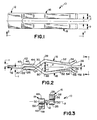
- the terminal 10 is stamped from a flat metallic material to define a base 12 and a pair of cantilevered leaf spring beams 16 and 18 extending from the base 12. More particularly, the beams 16 and 18 from the top view as shown in FIG. 1 are substantially parallel to one another with a gap of dimension "a" therebetween.
- the beams 16 and 18 are of substantially identical width "b", and are symmetrical about the center line l, of the terminal 10.
- the beams 16 and 18 of terminal 10 are of multiple bend configuration relative to the plane "p" extending centrally through the base 12 of terminal 10.
- the beam 16 is stamped to undergo a first bend 20 away from central plane "p ⁇ substantially adjacent the base 12, and to undergo a second bend 22 substantially adjacent the bend 20 but in the opposite direction.
- a third bend 24 spaced from the bend 22 directs the beam 16 back toward and across the central plane "p".
- a rearward contact surface 26 is defined intermediate the bends 22 and 24, with the rearward contact surface being approximately parallel to the plane "p” but offset therefrom by a distance "c".
- the beam 16 extends from the radiused bend 24 across the central plane "p" to a fourth bend 28.
- a rearward cam surface 30 is defined between the bends 24 and 28 and on the same side of the beam 16 as the rearward contact surface 26.
- the rearward cam surface 30 with its radiused surface at bend 24 effectively leads into the rearward contact surface 26 as explained in greater detail below.
- the distance between the bends 24 and 28 is such that the interior corner of bend 28 is spaced from the center plane "p" by a distance "d" which exceeds the distance "c" by which the rearward contact surface 26 is spaced from the central plane "p".
- the bend 28 is of a sufficient magnitude such that the portion 32 of the beam 16 extends back toward the plane "p".
- the beam 16 then is provided with a fifth bend 34 which extends away from the central plane “p” to define a forward contact surface 36 which is spaced from the central plane "p" by a distance "e"
- the length of portion 32 of the cantilevered beam 16 and the angular magnitude of bend 28 are selected such that the distance "e ⁇ between the forward contact surface 36 and central plane "p ⁇ is less than the distance "c" between the rearward contact surface 26 and the central plane "p".
- the portion of the beam 16 beyond the bend 36 is angularly aligned to the central plane "p” and radiused to define a forward cam surface 38.
- the rearward and forward cam surfaces 30 and 38 may define approximately equal angles to the central plane "p ⁇ , as shown, so that they are approximately parallel, or the forward cam surface 38 may be more sharply angled to the central plane so that a radiused surface at bend 36 rides on rearward cam surface 30.
- the second cantilevered contact beam 18 is similar to the first beam 16, but is bent in opposite directions such that the beams 16 and 18 are substantially symmetrical about the central plane "p". More particularly, the beam 18 includes a first bend 40 which directs the beam 18 away from the central plane "p" and a second bend 42 adjacent to the first bend 40 but in the opposite direction. A third bend 44 is spaced from the second bend 42 to define a rearward contact surface 46 therebetween on the side of the beam 18 opposite the central plane "p".
- the rearward contact surfaces 26 and 46 of the respective beams 16 and 18 are of substantially identical length and are disposed at substantially the same axial position along the terminal 10. Additionally, the rearward contact surface 46 is offset from the central plane "p" by a distance "c ⁇ , which is substantially equal to the offset of the rearward contact surface 26 as explained above.
- the bend 44 in the second contact beam 18 is of sufficient magnitude to direct the second contact beam 18 back toward and across the central plane "p" to a fourth bend 48.
- a rearward cam surface 50 of beam 18 is defined between the bends 44 and 48 and on the same side of beam 18 as the rearward contact surface 46 thereof.
- the distance between the bends 44 and 48 on the second beam is such that the internal corner defined by bend 48 is spaced from the central plane "p ⁇ by a distance "d” which is greater than the distance "c" between the rearward contact surface 46 of beam 18 and the central plane "p".
- the magnitude of bend 48 is such that the portion 52 of the second beam 18 extends back toward the central plane "p" to a fifth bend 54.
- the fifth bend 54 defines the forward contact surface 56 of the second beam 18.
- the magnitude of bend 48 and the length of portion 52 are such that the forward contact surface 56 is spaced from the central plane "p" by a distance "e” which is less than the distance "c ⁇ by which the rearward contact surface 26 is offset from the central plane.
- a forward cam surface 58 is defined on the second beam 18 adjacent the forward contact surface 56.
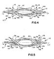
- the hermaphroditic terminal 10 can be employed with a substantially identical terminal 110 to achieve a low insertion force but a high normal contact force in the fully mated condition of the substantially identical hermaphroditic terminals 10 and 110.
- the first beam 116 of terminal 110 will mate with the second beam 18 of terminal 10
- the first beam 16 of terminal 10 will mate with the second beam 118 of terminal 110.
- This mating is achieved by placing the terminals 10 and 110 in opposed relationship such that their central planes "p" and "p′" and their centerlines (not shown) are approximately aligned with one another. This initial approximate alignment typically would be achieved by an appropriate housing, such as a drawer housing.
- the terminals 10 and 110 will then be advanced axially toward one another into the partly mated condition as shown in FIG. 4.
- the forward contact surface 56 of beam 18 will move past the forward contact surface 136 of beam 116 without direct contact, since the respective forward contact surfaces 58 and 136 are disposed on opposite sides of the approximately aligned central planes "p" and "p′".
- the respective forward cam surfaces 38, 58, 138 and 158 will engage in a sliding camming action with the corresponding rearward cam surfaces 150, 130, 50 and 30 respectively.
- each forward contact surface 36, 56, 136 and 156 is on a portion of the respective beam 16, 18, 116 and 118 which after plural bends is directed back toward the central plane p, p′.
- each beam 16 and 18 has generally flat contact and camming surfaces.
- contact will exist between mating terminals 10, 110.
- the limitation in such side to side misalignment is largely controlled by the width "b" of each beam 16, 18 of terminal 10.
- an improved mating electrical contact structure has been described in a hermaphroditic terminal 10 including dual cantilevered leaf spring contact beams 16, 18.
- the terminal is stamped from generally flat metallic material with the two beams being in generally parallel spaced apart alignment and extending from a common base 12.
- Each beam undergoes a plurality of opposite bends relative to the central plane of the base such that the beams are substantially symmetrical around the central plane P.
- the beams undergo a first series of bends to one side of the plane to define a rearward contact surface 26, 46.
- the beams then bend back across the central plane to define rearward cam surfaces, 30, 50 which lead with a radius into the rearward contact surfaces.
- Forward contact surfaces 36, 56 are defined at locations remote from the base and spaced from the central plane a distance less than the spacing between the rearward contact surfaces and the central plane.
- the extreme ends of each beam undergo further bends away from the central plane to define forward cam surfaces 38, 58.
- Identical hermaphroditic terminals 10, 110 as described above are mated such that a low insertion force sliding camming interaction occurs between respective forward and rearward cam surfaces 38, 50 and 58, 30. This camming interaction results in a gradual deflection of the beams as the contact portions of the terminals approach their fully mated condition.
- the respective rearward and forward contact surfaces 46, 36 and 26, 56 achieve a sliding contact with high normal forces, and with a total of four independent points of electrical contact for each mated pair of hermaphroditic terminals.
- the bends at 24 or 44 between the rearward camming surfaces 30 and 50 and rearward contact surfaces 26 and 56, respectively, may be staggered with respect to each other in the axial direction. This would provide a rear contact surface on one beam which is longer than the other rearward contact surface on the other beam. Mating of two of these terminals so modified would further reduce the overall peak insertion force associated with mating because camming engagement of one pair of beams at a time would occur. The lifting components for each pair of beams would be instead of separated occurring simultaneously, which would tend to reduce the overall peak insertion force of the mated contacts.
- the terminals 10, 110 achieve both low insertion forces and high electrical contact forces without movable parts in their respective housings. Acceptably high electrical contact forces are provided despite misalignments of the hermaphroditic terminals relative to one another.
- the terminals have multiple or redundant contact locations and plural camming lead-in surfaces to achieve low insertion forces. The terminals gradually increase the contact forces as the contacts are urged into their fully mated conditions.
Landscapes
- Coupling Device And Connection With Printed Circuit (AREA)
Applications Claiming Priority (2)
| Application Number | Priority Date | Filing Date | Title |
|---|---|---|---|
| US07/134,635 US4820182A (en) | 1987-12-18 | 1987-12-18 | Hermaphroditic L. I. F. mating electrical contacts |
| US134635 | 1987-12-18 |
Publications (3)
| Publication Number | Publication Date |
|---|---|
| EP0321257A2 true EP0321257A2 (de) | 1989-06-21 |
| EP0321257A3 EP0321257A3 (en) | 1990-05-09 |
| EP0321257B1 EP0321257B1 (de) | 1993-04-28 |
Family
ID=22464253
Family Applications (1)
| Application Number | Title | Priority Date | Filing Date |
|---|---|---|---|
| EP88311900A Expired - Lifetime EP0321257B1 (de) | 1987-12-18 | 1988-12-16 | Hermaphroditische elektrische Steckkontakte mit niedriger Einschubkraft |
Country Status (5)
| Country | Link |
|---|---|
| US (1) | US4820182A (de) |
| EP (1) | EP0321257B1 (de) |
| JP (1) | JPH01204377A (de) |
| BR (1) | BR8806667A (de) |
| DE (1) | DE3880646T2 (de) |
Cited By (5)
| Publication number | Priority date | Publication date | Assignee | Title |
|---|---|---|---|---|
| WO1998009354A1 (en) * | 1996-08-30 | 1998-03-05 | The Whitaker Corporation | Ground-power plane connector |
| EP0806813A3 (de) * | 1996-05-10 | 1998-12-09 | Molex Incorporated | Elektrischer Steckverbinder mit verbesserten Kontaktstückhaltemitteln |
| EP1702389A4 (de) * | 2003-12-31 | 2008-02-20 | Fci Americas Technology Inc | Elektrische leistungskontakte und verbinder damit |
| EP2096717A1 (de) * | 2008-02-26 | 2009-09-02 | Delphi Technologies, Inc. | Elektrisches Kontaktelement |
| US9831605B2 (en) | 2012-04-13 | 2017-11-28 | Fci Americas Technology Llc | High speed electrical connector |
Families Citing this family (52)
| Publication number | Priority date | Publication date | Assignee | Title |
|---|---|---|---|---|
| JPH0284273U (de) * | 1988-12-17 | 1990-06-29 | ||
| US5098311A (en) * | 1989-06-12 | 1992-03-24 | Ohio Associated Enterprises, Inc. | Hermaphroditic interconnect system |
| US4995824A (en) * | 1989-10-23 | 1991-02-26 | Cabot Corporation | Line coupling device |
| US5290181A (en) * | 1993-01-29 | 1994-03-01 | Molex Incorporated | Low insertion force mating electrical contact structure |
| ES2117553B1 (es) * | 1993-12-23 | 2000-09-01 | Motorola Inc | Contacto de doble brazo. |
| US5664973A (en) * | 1995-01-05 | 1997-09-09 | Motorola, Inc. | Conductive contact |
| US5692928A (en) * | 1996-05-10 | 1997-12-02 | Molex Incorporated | Electrical connector having terminals with improved retention means |
| US6102754A (en) * | 1997-03-31 | 2000-08-15 | The Whitaker Corporation | Bus bar contact |
| US6129592A (en) * | 1997-11-04 | 2000-10-10 | The Whitaker Corporation | Connector assembly having terminal modules |
| US6193537B1 (en) | 1999-05-24 | 2001-02-27 | Berg Technology, Inc. | Hermaphroditic contact |
| US7458839B2 (en) * | 2006-02-21 | 2008-12-02 | Fci Americas Technology, Inc. | Electrical connectors having power contacts with alignment and/or restraining features |
| US7335043B2 (en) * | 2003-12-31 | 2008-02-26 | Fci Americas Technology, Inc. | Electrical power contacts and connectors comprising same |
| JP2006049130A (ja) * | 2004-08-05 | 2006-02-16 | D D K Ltd | 電気コネクタ |
| US20060121420A1 (en) * | 2004-11-18 | 2006-06-08 | Michael Athanas | Pilot seat positioning device |
| US7476108B2 (en) * | 2004-12-22 | 2009-01-13 | Fci Americas Technology, Inc. | Electrical power connectors with cooling features |
| US7384289B2 (en) | 2005-01-31 | 2008-06-10 | Fci Americas Technology, Inc. | Surface-mount connector |
| US7303427B2 (en) | 2005-04-05 | 2007-12-04 | Fci Americas Technology, Inc. | Electrical connector with air-circulation features |
| US7425145B2 (en) * | 2006-05-26 | 2008-09-16 | Fci Americas Technology, Inc. | Connectors and contacts for transmitting electrical power |
| US7726982B2 (en) * | 2006-06-15 | 2010-06-01 | Fci Americas Technology, Inc. | Electrical connectors with air-circulation features |
| US7641500B2 (en) * | 2007-04-04 | 2010-01-05 | Fci Americas Technology, Inc. | Power cable connector system |
| US7905731B2 (en) * | 2007-05-21 | 2011-03-15 | Fci Americas Technology, Inc. | Electrical connector with stress-distribution features |
| US7635278B2 (en) * | 2007-08-30 | 2009-12-22 | Fci Americas Technology, Inc. | Mezzanine-type electrical connectors |
| US7762857B2 (en) | 2007-10-01 | 2010-07-27 | Fci Americas Technology, Inc. | Power connectors with contact-retention features |
| US8147254B2 (en) * | 2007-11-15 | 2012-04-03 | Fci Americas Technology Llc | Electrical connector mating guide |
| US8062051B2 (en) * | 2008-07-29 | 2011-11-22 | Fci Americas Technology Llc | Electrical communication system having latching and strain relief features |
| US8277241B2 (en) * | 2008-09-25 | 2012-10-02 | Fci Americas Technology Llc | Hermaphroditic electrical connector |
| US7976326B2 (en) * | 2008-12-31 | 2011-07-12 | Fci Americas Technology Llc | Gender-neutral electrical connector |
| USD664096S1 (en) | 2009-01-16 | 2012-07-24 | Fci Americas Technology Llc | Vertical electrical connector |
| USD610548S1 (en) | 2009-01-16 | 2010-02-23 | Fci Americas Technology, Inc. | Right-angle electrical connector |
| USD608293S1 (en) | 2009-01-16 | 2010-01-19 | Fci Americas Technology, Inc. | Vertical electrical connector |
| USD640637S1 (en) | 2009-01-16 | 2011-06-28 | Fci Americas Technology Llc | Vertical electrical connector |
| USD606496S1 (en) | 2009-01-16 | 2009-12-22 | Fci Americas Technology, Inc. | Right-angle electrical connector |
| USD606497S1 (en) | 2009-01-16 | 2009-12-22 | Fci Americas Technology, Inc. | Vertical electrical connector |
| US8323049B2 (en) | 2009-01-30 | 2012-12-04 | Fci Americas Technology Llc | Electrical connector having power contacts |
| USD619099S1 (en) | 2009-01-30 | 2010-07-06 | Fci Americas Technology, Inc. | Electrical connector |
| US8366485B2 (en) | 2009-03-19 | 2013-02-05 | Fci Americas Technology Llc | Electrical connector having ribbed ground plate |
| USD618180S1 (en) | 2009-04-03 | 2010-06-22 | Fci Americas Technology, Inc. | Asymmetrical electrical connector |
| USD618181S1 (en) | 2009-04-03 | 2010-06-22 | Fci Americas Technology, Inc. | Asymmetrical electrical connector |
| US9024486B2 (en) * | 2010-08-20 | 2015-05-05 | Rockwell Automation Technologies, Inc. | Adaptable automation control module with integrated power bus distributor |
| EP2624034A1 (de) | 2012-01-31 | 2013-08-07 | Fci | Abbaubare optische Kupplungsvorrichtung |
| US8944831B2 (en) | 2012-04-13 | 2015-02-03 | Fci Americas Technology Llc | Electrical connector having ribbed ground plate with engagement members |
| USD718253S1 (en) | 2012-04-13 | 2014-11-25 | Fci Americas Technology Llc | Electrical cable connector |
| USD727852S1 (en) | 2012-04-13 | 2015-04-28 | Fci Americas Technology Llc | Ground shield for a right angle electrical connector |
| USD727268S1 (en) | 2012-04-13 | 2015-04-21 | Fci Americas Technology Llc | Vertical electrical connector |
| US9543703B2 (en) | 2012-07-11 | 2017-01-10 | Fci Americas Technology Llc | Electrical connector with reduced stack height |
| USD751507S1 (en) | 2012-07-11 | 2016-03-15 | Fci Americas Technology Llc | Electrical connector |
| USD745852S1 (en) | 2013-01-25 | 2015-12-22 | Fci Americas Technology Llc | Electrical connector |
| USD720698S1 (en) | 2013-03-15 | 2015-01-06 | Fci Americas Technology Llc | Electrical cable connector |
| CN106654751B (zh) * | 2016-11-30 | 2019-02-15 | 中航光电科技股份有限公司 | 导电接触件及使用该导电接触件的电连接器 |
| US10381770B1 (en) | 2018-02-27 | 2019-08-13 | Ohio Associated Enterprises, Llc | Protective grid for linear electrical contact array |
| CN116014475A (zh) * | 2023-01-18 | 2023-04-25 | 深圳市长盈精密技术股份有限公司 | 一种端子配合结构及高速背板连接器组件 |
| CN119153981B (zh) * | 2024-11-19 | 2025-04-22 | 昆山铭众电子科技有限公司 | 一种电连接器及连接器雌雄同体连接结构 |
Family Cites Families (7)
| Publication number | Priority date | Publication date | Assignee | Title |
|---|---|---|---|---|
| CH218200A (de) * | 1941-03-06 | 1941-11-30 | Hasler Ag | Elektrisches Verbindungsorgan. |
| US3011143A (en) * | 1959-02-10 | 1961-11-28 | Cannon Electric Co | Electrical connector |
| US3072340A (en) * | 1960-09-16 | 1963-01-08 | Cannon Electric Co | Electrical connector insulator block construction |
| US3115379A (en) * | 1961-11-29 | 1963-12-24 | United Carr Fastener Corp | Electrical connector |
| GB1014548A (en) * | 1963-09-20 | 1965-12-31 | Atomic Energy Authority Uk | Horizontal seismometer |
| JPS5324885B2 (de) * | 1972-11-08 | 1978-07-24 | ||
| JPS5917571B2 (ja) * | 1980-04-04 | 1984-04-21 | 富士通株式会社 | パルス検出回路 |
-
1987
- 1987-12-18 US US07/134,635 patent/US4820182A/en not_active Expired - Fee Related
-
1988
- 1988-12-12 JP JP63313661A patent/JPH01204377A/ja active Pending
- 1988-12-16 BR BR888806667A patent/BR8806667A/pt unknown
- 1988-12-16 DE DE88311900T patent/DE3880646T2/de not_active Expired - Fee Related
- 1988-12-16 EP EP88311900A patent/EP0321257B1/de not_active Expired - Lifetime
Cited By (6)
| Publication number | Priority date | Publication date | Assignee | Title |
|---|---|---|---|---|
| EP0806813A3 (de) * | 1996-05-10 | 1998-12-09 | Molex Incorporated | Elektrischer Steckverbinder mit verbesserten Kontaktstückhaltemitteln |
| CN1098544C (zh) * | 1996-05-10 | 2003-01-08 | 莫列斯公司 | 具有带有改进的保持装置的端子的电气连接器 |
| WO1998009354A1 (en) * | 1996-08-30 | 1998-03-05 | The Whitaker Corporation | Ground-power plane connector |
| EP1702389A4 (de) * | 2003-12-31 | 2008-02-20 | Fci Americas Technology Inc | Elektrische leistungskontakte und verbinder damit |
| EP2096717A1 (de) * | 2008-02-26 | 2009-09-02 | Delphi Technologies, Inc. | Elektrisches Kontaktelement |
| US9831605B2 (en) | 2012-04-13 | 2017-11-28 | Fci Americas Technology Llc | High speed electrical connector |
Also Published As
| Publication number | Publication date |
|---|---|
| EP0321257B1 (de) | 1993-04-28 |
| US4820182A (en) | 1989-04-11 |
| JPH01204377A (ja) | 1989-08-16 |
| DE3880646D1 (de) | 1993-06-03 |
| DE3880646T2 (de) | 1993-11-11 |
| BR8806667A (pt) | 1989-08-29 |
| EP0321257A3 (en) | 1990-05-09 |
Similar Documents
| Publication | Publication Date | Title |
|---|---|---|
| EP0321257B1 (de) | Hermaphroditische elektrische Steckkontakte mit niedriger Einschubkraft | |
| EP0510995B1 (de) | Elektrischer Verbinder mit zuverlässigen Anschlüssen | |
| US6695627B2 (en) | Profiled header ground pin | |
| US4664456A (en) | High durability drawer connector | |
| EP0702429B1 (de) | Polarisationselemente für elektrisches Verbindersystem mit Einsteckhilfe | |
| EP0717463A2 (de) | Flachprofil-, oberflächenmontierbare elektrische Verbinderanordnung | |
| EP0685120B1 (de) | Messerkontakt mit einer passiven verriegelungsvorrichtung | |
| US5830018A (en) | Low profile surface mountable electrical connector assembly | |
| CA2106369A1 (en) | Board to board interconnect | |
| EP0340952A1 (de) | Steckverbindergehäuse mit bewegbaren Endstücken | |
| US5174764A (en) | Connector assembly having surface mounted terminals | |
| DE69609733T2 (de) | Verbindungssystem für tragbares telefon | |
| JP3325050B2 (ja) | コネクタ組立体 | |
| US6077092A (en) | Electrical connector having stabilizing structure for spacer and terminal | |
| US6629853B2 (en) | Self-aligning power connector system | |
| US20040166739A1 (en) | Electrical connector with a terminal pin stabilizing plate | |
| US3663930A (en) | Disengageable electrical connector | |
| EP0199619B1 (de) | Erstein- und Letztausschaltkontakt für Steckverbindersystem mit geringer Einsteckkraft | |
| WO2000059073A1 (en) | Female electrical terminal with arc arresting portion | |
| EP0308068B1 (de) | Kontaktsystem mit geringem Verschleiss | |
| EP0008221B2 (de) | Elektrischer Endkontakt und ihn enthaltender Steckverbinder | |
| EP0218325B1 (de) | Stift aufnehmende Klemme | |
| US20260045716A1 (en) | Reliable high-speed, high-current electrical connector | |
| WO2026011734A1 (zh) | 连接器组件、第一连接器和第二连接器及线缆、电子设备 | |
| CN119852758A (zh) | 导电端子、线端连接器以及电连接组合 |
Legal Events
| Date | Code | Title | Description |
|---|---|---|---|
| PUAI | Public reference made under article 153(3) epc to a published international application that has entered the european phase |
Free format text: ORIGINAL CODE: 0009012 |
|
| AK | Designated contracting states |
Kind code of ref document: A2 Designated state(s): DE FR GB IT SE |
|
| PUAL | Search report despatched |
Free format text: ORIGINAL CODE: 0009013 |
|
| AK | Designated contracting states |
Kind code of ref document: A3 Designated state(s): DE FR GB IT SE |
|
| 17P | Request for examination filed |
Effective date: 19901015 |
|
| 17Q | First examination report despatched |
Effective date: 19920806 |
|
| GRAA | (expected) grant |
Free format text: ORIGINAL CODE: 0009210 |
|
| ITF | It: translation for a ep patent filed | ||
| AK | Designated contracting states |
Kind code of ref document: B1 Designated state(s): DE FR GB IT SE |
|
| ET | Fr: translation filed | ||
| REF | Corresponds to: |
Ref document number: 3880646 Country of ref document: DE Date of ref document: 19930603 |
|
| PLBE | No opposition filed within time limit |
Free format text: ORIGINAL CODE: 0009261 |
|
| STAA | Information on the status of an ep patent application or granted ep patent |
Free format text: STATUS: NO OPPOSITION FILED WITHIN TIME LIMIT |
|
| 26N | No opposition filed | ||
| EAL | Se: european patent in force in sweden |
Ref document number: 88311900.0 |
|
| PGFP | Annual fee paid to national office [announced via postgrant information from national office to epo] |
Ref country code: GB Payment date: 19991112 Year of fee payment: 12 |
|
| PGFP | Annual fee paid to national office [announced via postgrant information from national office to epo] |
Ref country code: SE Payment date: 19991202 Year of fee payment: 12 Ref country code: FR Payment date: 19991202 Year of fee payment: 12 |
|
| PGFP | Annual fee paid to national office [announced via postgrant information from national office to epo] |
Ref country code: DE Payment date: 19991222 Year of fee payment: 12 |
|
| PG25 | Lapsed in a contracting state [announced via postgrant information from national office to epo] |
Ref country code: GB Free format text: LAPSE BECAUSE OF NON-PAYMENT OF DUE FEES Effective date: 20001216 |
|
| PG25 | Lapsed in a contracting state [announced via postgrant information from national office to epo] |
Ref country code: SE Free format text: LAPSE BECAUSE OF NON-PAYMENT OF DUE FEES Effective date: 20001217 |
|
| GBPC | Gb: european patent ceased through non-payment of renewal fee |
Effective date: 20001216 |
|
| EUG | Se: european patent has lapsed |
Ref document number: 88311900.0 |
|
| PG25 | Lapsed in a contracting state [announced via postgrant information from national office to epo] |
Ref country code: FR Free format text: LAPSE BECAUSE OF NON-PAYMENT OF DUE FEES Effective date: 20010831 |
|
| REG | Reference to a national code |
Ref country code: FR Ref legal event code: ST |
|
| PG25 | Lapsed in a contracting state [announced via postgrant information from national office to epo] |
Ref country code: DE Free format text: LAPSE BECAUSE OF NON-PAYMENT OF DUE FEES Effective date: 20011002 |
|
| PG25 | Lapsed in a contracting state [announced via postgrant information from national office to epo] |
Ref country code: IT Free format text: LAPSE BECAUSE OF NON-PAYMENT OF DUE FEES;WARNING: LAPSES OF ITALIAN PATENTS WITH EFFECTIVE DATE BEFORE 2007 MAY HAVE OCCURRED AT ANY TIME BEFORE 2007. THE CORRECT EFFECTIVE DATE MAY BE DIFFERENT FROM THE ONE RECORDED. Effective date: 20051216 |