EP0320508B2 - Debimetre de masse de coriolis ameliore a chemin parallele - Google Patents
Debimetre de masse de coriolis ameliore a chemin parallele Download PDFInfo
- Publication number
- EP0320508B2 EP0320508B2 EP87906225A EP87906225A EP0320508B2 EP 0320508 B2 EP0320508 B2 EP 0320508B2 EP 87906225 A EP87906225 A EP 87906225A EP 87906225 A EP87906225 A EP 87906225A EP 0320508 B2 EP0320508 B2 EP 0320508B2
- Authority
- EP
- European Patent Office
- Prior art keywords
- mounting block
- meter
- orifice
- flow tubes
- fluid
- Prior art date
- Legal status (The legal status is an assumption and is not a legal conclusion. Google has not performed a legal analysis and makes no representation as to the accuracy of the status listed.)
- Expired - Lifetime
Links
- 239000012530 fluid Substances 0.000 claims abstract description 67
- 230000007704 transition Effects 0.000 claims abstract description 39
- 230000010355 oscillation Effects 0.000 claims description 17
- 238000003466 welding Methods 0.000 claims description 15
- 239000000463 material Substances 0.000 claims description 11
- SGPGESCZOCHFCL-UHFFFAOYSA-N Tilisolol hydrochloride Chemical compound [Cl-].C1=CC=C2C(=O)N(C)C=C(OCC(O)C[NH2+]C(C)(C)C)C2=C1 SGPGESCZOCHFCL-UHFFFAOYSA-N 0.000 claims 6
- 239000000155 melt Substances 0.000 abstract description 2
- 238000005219 brazing Methods 0.000 description 21
- 238000005259 measurement Methods 0.000 description 18
- 238000013461 design Methods 0.000 description 10
- 238000000034 method Methods 0.000 description 6
- 238000005452 bending Methods 0.000 description 5
- 230000008569 process Effects 0.000 description 5
- 230000006698 induction Effects 0.000 description 4
- 125000006850 spacer group Chemical group 0.000 description 4
- 230000007423 decrease Effects 0.000 description 3
- 230000007246 mechanism Effects 0.000 description 3
- 230000000694 effects Effects 0.000 description 2
- 239000007789 gas Substances 0.000 description 2
- 238000007689 inspection Methods 0.000 description 2
- 238000004519 manufacturing process Methods 0.000 description 2
- 238000002844 melting Methods 0.000 description 2
- 230000008018 melting Effects 0.000 description 2
- 230000035945 sensitivity Effects 0.000 description 2
- 238000013459 approach Methods 0.000 description 1
- 230000015572 biosynthetic process Effects 0.000 description 1
- 239000008280 blood Substances 0.000 description 1
- 210000004369 blood Anatomy 0.000 description 1
- 230000008859 change Effects 0.000 description 1
- 238000011143 downstream manufacturing Methods 0.000 description 1
- 230000004907 flux Effects 0.000 description 1
- 238000003780 insertion Methods 0.000 description 1
- 230000037431 insertion Effects 0.000 description 1
- 230000007774 longterm Effects 0.000 description 1
- 238000000691 measurement method Methods 0.000 description 1
- OCDRLZFZBHZTKQ-NMUBGGKPSA-N onetine Chemical compound C[C@@H](O)[C@@]1(O)C[C@@H](C)[C@@](C)(O)C(=O)OC\C2=C\CN(C)CC[C@@H](OC1=O)C2=O OCDRLZFZBHZTKQ-NMUBGGKPSA-N 0.000 description 1
- 230000003287 optical effect Effects 0.000 description 1
- 230000003534 oscillatory effect Effects 0.000 description 1
- 230000010363 phase shift Effects 0.000 description 1
- 238000005086 pumping Methods 0.000 description 1
- 230000002787 reinforcement Effects 0.000 description 1
- 238000012552 review Methods 0.000 description 1
- 238000006467 substitution reaction Methods 0.000 description 1
- 239000013598 vector Substances 0.000 description 1
Images


Classifications
-
- G—PHYSICS
- G01—MEASURING; TESTING
- G01F—MEASURING VOLUME, VOLUME FLOW, MASS FLOW OR LIQUID LEVEL; METERING BY VOLUME
- G01F1/00—Measuring the volume flow or mass flow of fluid or fluent solid material wherein the fluid passes through a meter in a continuous flow
- G01F1/76—Devices for measuring mass flow of a fluid or a fluent solid material
- G01F1/78—Direct mass flowmeters
- G01F1/80—Direct mass flowmeters operating by measuring pressure, force, momentum, or frequency of a fluid flow to which a rotational movement has been imparted
- G01F1/84—Coriolis or gyroscopic mass flowmeters
- G01F1/8409—Coriolis or gyroscopic mass flowmeters constructional details
- G01F1/8413—Coriolis or gyroscopic mass flowmeters constructional details means for influencing the flowmeter's motional or vibrational behaviour, e.g., conduit support or fixing means, or conduit attachments
-
- G—PHYSICS
- G01—MEASURING; TESTING
- G01F—MEASURING VOLUME, VOLUME FLOW, MASS FLOW OR LIQUID LEVEL; METERING BY VOLUME
- G01F1/00—Measuring the volume flow or mass flow of fluid or fluent solid material wherein the fluid passes through a meter in a continuous flow
- G01F1/76—Devices for measuring mass flow of a fluid or a fluent solid material
- G01F1/78—Direct mass flowmeters
- G01F1/80—Direct mass flowmeters operating by measuring pressure, force, momentum, or frequency of a fluid flow to which a rotational movement has been imparted
- G01F1/84—Coriolis or gyroscopic mass flowmeters
- G01F1/845—Coriolis or gyroscopic mass flowmeters arrangements of measuring means, e.g., of measuring conduits
- G01F1/8468—Coriolis or gyroscopic mass flowmeters arrangements of measuring means, e.g., of measuring conduits vibrating measuring conduits
- G01F1/8472—Coriolis or gyroscopic mass flowmeters arrangements of measuring means, e.g., of measuring conduits vibrating measuring conduits having curved measuring conduits, i.e. whereby the measuring conduits' curved center line lies within a plane
- G01F1/8477—Coriolis or gyroscopic mass flowmeters arrangements of measuring means, e.g., of measuring conduits vibrating measuring conduits having curved measuring conduits, i.e. whereby the measuring conduits' curved center line lies within a plane with multiple measuring conduits
-
- G—PHYSICS
- G01—MEASURING; TESTING
- G01F—MEASURING VOLUME, VOLUME FLOW, MASS FLOW OR LIQUID LEVEL; METERING BY VOLUME
- G01F15/00—Details of, or accessories for, apparatus of groups G01F1/00 - G01F13/00 insofar as such details or appliances are not adapted to particular types of such apparatus
- G01F15/18—Supports or connecting means for meters
- G01F15/185—Connecting means, e.g. bypass conduits
Definitions
- the present invention relates to apparatus for a parallel path Coriolis mass flow meter and, more particularly, to such a mass flow meter which is easier to fabricate and which has improved measurement accuracy than prior art designs.
- Coriolis mass flow rate meters When a fluid flows through a rotating or oscillating conduit Coriolis forces are produced which are perpendicular to both the velocity of the fluid moving through the conduit and the angular velocity of the rotating or oscillating conduit. The magnitude of these Coriolis forces is proportional to the product of the mass flow rate and the angular velocity of the conduit. Meters which make use of this phenomenon are termed Coriolis mass flow rate meters.
- U.S. Reissue Patent 31,450 (issued to Smith on November 29, 1983 and hereinafter referred to as the '450 reissue patent).
- This patent discloses a mechanical configuration which incorporates a U-shaped flow tube, devoid of pressure sensitive joints, which has its open ends attached to opposite sides of a manifold. When so mounted, this flow tube is capable of being oscillated about an axis perpendicular to the side legs of the U-shaped tube. This axis is located near the tube-manifold interface and is situated in a plane in which the U-shaped tube lies at rest.
- This plane is hereinafter referred to as the midplane of oscillation.
- the filled flow tube oscillates. These oscillations are sufficient to cause the free end of the flow tube to pass through the mid-plane of oscillation, and thereby generate a Coriolis force couple which elastically deflects the free end of the flow tube about an axis.
- This axis is located in the plane of the flow tube midway between and parallel to its side legs.
- the '450 reissue patent also teaches the use of a spring arm which extends from the manifold along with the U-shaped flow tube.
- this spring arm is sinusoidally driven in opposition to the U-shaped flow tube, the combination of spring arm and U-shaped flow tube operates as a tuning fork.
- This operation substantially attenuates undesirable vibrations occurring at the tube-manifold and spring arm-manifold interfaces. This attenuation is extremely advantageous for the following reason. In practice, these undesirable vibrations, often occur, particularly at the tube-manifold interfaces, with sufficient intensity to effectively mask tube movement caused by the small Coriolis forces and thereby introduce significant errors into the time interval measurements of the passage of the side legs of the U-shaped tribe through the mid-plane of oscillation.
- each parallel flow tube may be constructed with relatively thin walls which, in tum, provides increased sensitivity. As the wall thickness of a flow tube decreases, the mass and rigidity of the tube also decreases which, in turn, increases tube deflection caused by Coriolis forces. Increasing the deflection for à given mass flow rate advantageously increases the sensitivity of the meter.
- parallel tube flow meters are, in general, operationally more stable than either single flow tube or serial flow tube meters. This occurs because the fluid flowing through both tubes results in a dynamically balanced pair of tuning fork tines, i.e., as the mass of one tine varies due to increased fluid density so will the mass of the other tine.
- parallel flow tube meters are less sensitive to error-producing external vibrations and, hence, provide more accurate fluid flow measurements than do single tube or serial tube flow meters. This occurs because the time interval measurement sensors can be mounted on the flow tubes without a physical reference to any structure that is immutably fixed with respect to the mid-planes of oscillation for the tubes. Fourth, parallel flow tube meters exhibit less pressure drop across the entire meter than does a serial flow tube meter.
- the parallel flow tubes extend from a two piece manifold having a transition piece and a the mounting block mounted thereto.
- the transition piece has a fluid-conducting passageway extending therethrough whose cross section smoothly varies from a first aperture at the inlet to a second aperture, different than the first, at a transition piece-tube mounting block interface.
- the first and second apertures have round and oval cross sections, respectively.
- the tube mounting block has two parallel openings extending therethrough which are separated bi an internal wall and which align the flow tubes in a parallel relationship. This intemal wall has a smooth wedge shape so as to smoothly divide the fluid entering the flow tubes and smoothly combine the fluid exiting from the flow tubes.
- the parallel openings through the tube mounting block each incorporate an intemal shoulder which serves as an alignment reference point for the ends of the flow tubes. This relationship is then maintained and a fluid-tight connection is provided by deforming the intemal shoulder using heat to weld the tube ends and mounting block together.
- the tube mounting block also has an extemal geometry configured for reinforcement brazing of the flow tubes and welding of the transition piece thereto.
- US-A-3 944 261 describes a similar manifold for blood handling.
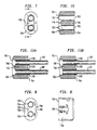
- FIG. 1 shows a parallel path Coriolis mass flowmeter 10 which incorporates the teachings of the present invention.
- meter 10 indudes a pair of manifolds 100 and 100' ; tubular member 150 ; a pair of parallel flow tubes 130 and 130'; drive mechanism 180; a pair of coils 160 and 160' ; and a pair of permanent magnets 161 and 161'.
- manifolds 100 and 100' respectively, include transition pieces 110 and 110' and tube mounting blocks 120 and 120', respectively.
- Tubes 130 and 130' are substantially U-shaped and have their ends attached to tube mounting blocks 120 and 120'. Both tubes are free of pressure sensitive joints.
- a continuous closed fluid path is provided through meter 10.
- meter 10 when meter 10 is connected, via inlet end 101 and outlet end 101', into a conduit system (not shown) in which the mass flow rate of a fluid flowing therethrough is to be determined, fluid in the system enters the meter through an orifice in inlet end 101 of transition piece 110 and is conducted through a passageway therein having a gradually changing cross-section to an orifice in a second end adjacent to tube mounting block 120. The fluid then flows through tube mounting block 120 where it is evenly divided and conducted through tubes 130 and 130'.
- the fluid Upon exiting tubes 130 and 130', the fluid is recombined in a single stream within tube mounting block 120' and is thereafter conducted through an opening to transition piece 110'.
- transition piece 110' the fluid flows through a passageway having a gradually changing cross-section to an orifice in outlet end 101'.
- the fluid reenters the conduit system.
- Tubular member 150 does not conduct any fluid. Instead, this member serves to axially align manifolds 100 and 100' and maintain the spacing therebetween by a pre-determined amount so that these manifolds will readily receive mounting blocks 120 and 120' and flow tubes 130 and 130'.
- U-shaped flow tubes 130 and 130' are selected and mounted so as to have substantially the same moments of inertia and spring constants about bending axes W-W and W'-W', respectively. These bending axes are perpendicular to the side legs of the U-shaped flow tubes 130 and 130', respectively, and are located near respective tube mounting blocks 120 and 120'.
- the U-shaped flow tubes extend outwardly from the mounting blocks in an essentially parallel fashion and have substantially equal moments of inertia and equal spring constants about their respective bending axes. Both of these flow tubes are sinusoidally driven in opposite directions about their bending axes but at essentially the same resonant frequency.
- Drive mechanism 180 supplies the sinusoidal driving forces to tubes 130 and 130'.
- Drive mechanism 180 can consist of any one of many well known arrangements, such as a magnet and a coil through which an alternating current is passed, for sinusoidally driving tubes 130 and 130' about their respective bending axes at their common resonant frequency.
- the adjacent side legs which are forced closer together than their counterpart side legs, will pass through the mid-planes of oscillation before their counterparts.
- the time interval which elapses from the instant one pair of adjacent side legs pass through their mid-planes of oscillation to the instant the counterpart pair of side legs, i.e., those forced further apart, pass through their mid-planes of oscillation is proportional to the total mass flow rate of the fluid flowing through the meter.
- the reader is referred to the '025 patent for a far more detailed discussion of the principles of operation of parallel path Coriolis flow meters than that just presented and, specifically, for the teaching that the mass flow rate can be determined from measurement of such time intervals.
- coils 160 and 160' are attached to either one of tubes 130 and 130' near their free ends and permanent magnets 161 and 161' are also attached near the free ends of the other one of the tubes. Magnets 161 and 161' are disposed so as to have coils 160 and 160' located in the volume of space surrounding the permanent magnets in which the magnetic flux fields are essentially constant.
- the electrical signal outputs generated by coils 160 and 160' provide a velocity profile of the complete travel of the tube and can be processed in well-known fashion to determine the time interval and, in tum, the mass flow rate.
- the fact that the midplane of oscillation is used as a timing reference point should not be considered as a limitation. Any predetermined point in the velocity signal can be used as the reference for the time interval measurement or phase shift between the two signals.
- FIG. 2 shows a partial perspective view of an assembly, used in a parallel path Coriolis flow rate meter, for mounting the flow tubes to the inlet and outlet manifolds of the meter in a manner known in the art.
- fluid enters the meter at a circular orifice in inlet end 271 of manifold 270 and is then conducted to two circular outlet orifices 280 formed in respective extensions of mounting surface 281.
- the fluid then flows through tubes 130 ant 130', enters manifold 270' at circular orifices 280' formed in extensions of mounting surface 281' and thereafter exits the meter, via a circular orifice in outlet end 271' of manifold 270'.
- substantially identical flow tube 130 and 130' coupled with the design of manifolds 270 and 270', evenly divides the fluid between tubes 130 and 130' and then recombines the flow prior to the fluid exiting the meter.
- the mass flow rate of the fluid flowing through flow tubes 130 and 130' is measured in the same manner, as described hereinabove, for the present invention.
- the two manifolds are welded to a spacer tube 290 which fixes the distance between each manifold.
- the flow tubes are brazed to a pair of spacer bars 250 and 250'.
- Each spacing bar is brazed to the tubes at a predetermined distance inward from the ends of the tubes. This distance is approximately equal to three diameters of the flow tube. Because it is extremely difficult to weld the small mass of each flow tube to the large mass of each manifold, the ends of each flow tube are first tack welded to slip collar 260 which increases the mass of material at the end of each flow tube.
- slip collars are required.
- the assembly of tubes, spacer bars and slip collars are welded to manifolds 270 and 270' in order to provide a fluid-tight connection between circular orifices 280 and 280' and the flow tubes.
- the slip collars and flow tubes are torch brazed to fill any and all remaining small clearance gaps occurring therebetween. This brazing reinforces the welds appearing between the slip collars and manifolds so that these welds are able to withstand any oscillations of the tube that occur during normal operation of the meter.
- the brazing operation must be performed after the welding operation because otherwise the brazing material will melt during welding due to the proximity of the brazing material to the location of the weld between the manifold and slip collar. Moreover, induction brazing, which is substantially faster and more uniform than torch brazing, cannot be performed due to the size of the assembly and the location of the areas to be brazed.
- the fluid pressure markedly drops in certain locations of the manifold and can approach the vapor pressure of the fluid and allow the formation of vapor cavities.
- Dissolved gases and gas bubbles in the fluid provide nucleative points and assist in the onset of cavitation.
- the pressure of the fluid recovers. This, in tum, causes the vapor cavities to implode. Cavitation is more likely to occur at high flow rates and can be a source of random vibrations in the manifolds and the flow tubes. As such, cavitation can inject error into the measarement of the Coriolis force.
- FIGS. 3-6 show the details of transition pieces 110 and 110' appearing in FIG. 1 and used in the present invention.
- Each piece formed of a unitary cast structure, conducts fluid, via passageway 303, between orifice 301 in end 101 or 101' to orifice 302 in end 401.
- Orifices 301 and 302 advantageously have different cross sectional areas.
- orifice 302 has a substantially larger cross sectional area than orifice 301.
- the respective geometries of these orifices are different, with orifice 301 having a circular geometry and orifice 302 having an oval geometry.
- passageway 303 has a cross-section which gradually changes from the circular cross-section of orifice 301 to the oval cross-section of orifice 302.
- passageway 303 substantially reduces the likelihood that the pressure of the fluid will markedly drop anywhere within the transition piece. This, in turn, substantially eliminates the cavitation associated with the prior art design shown in FIG. 2 and, by doing so, advantageously removes a possible source of measurement inaccuracy.
- End 401 of each transition piece is substantially planar and has a slight bevel.
- the wall surrounding orifice 302 has a uniform thickness, as measured radially from the center of orifice 302. As will be discussed, this uniform thickness facilitates welding of transition pieces 110 and 110' to respective tube mounting blocks 120 and 120' (see FIG. 1).
- FIGs. 7-10 show various detailed views of tube mounting blocks 120 and 120' depicted In FIG. 1.
- Each mounting block has a fluid passageway which extends from opening 701 in end face 702 to a pair of openings 703 in end face 704.
- the cross-sectional area of opening 701 is substantially equal to that of orifice 302 in the transition piece shown in FIGs. 3-6, while the cross sectional area of opening 703 shown in FIGs. 7-10 is such that the latter opening can slidingly receive an end of flow tubes 130 or 130'.
- the wall thickness surrounding opening 701 is substantially identical to the wall thickness surrounding orifice 302.
- Each mounting block also indudes internal wall 706 which acts as a flow splitter and specifically divides opening 701 into two circular openings 703.
- Wall 706 extends from end 704 and tapers down to a smooth wedge-shaped end 710.
- End 710 is recessed from end 702 to permit circumferential welding of each tube end to the mounting block assembly prior to circumferentially welding the mounting blocks 120 and 120' to their respective transition pieces.
- end 710 divides the fluid evenly between tubes 130 and 130'.
- End 710 appearing in the other mounting block, e.g. block 120' recombines the fluid flowing from both flow tubes.
- Each mounting block also incorporates shoulder 707 within each opening 703.
- This shoulder is located proximate to but recessed behind wall end 710 so as not to interfere with the flow dividing and combining function provided thereby.
- This shoulder not only serves as an alignment reference point for the ends of tubes 130 and 130' upon their insertion into openings 703 but also, during welding reaches its melting temperature before the remainder of the mounting block does, i.e. the temperature of the remainder of the mounting block remaisn below its melting point when the shoulder begins to melt, so as to advantageously become a sacrificial member in circumferentially welding the tubes in place and providing a fluid-tight connection between the flow tubes and the mounting block.
- the mounting block can be provided with a rib or other projection having a small mass in comparison to the mass of the wall of the mounting block which can serve as the sacrificial member for the welds.
- brazing material 1100 is added to fill in any small voids occurring between the tubes and mounting blocks.
- grooves 705 are formed in external surfaces 708 in the common region between the two openings 703. These grooves extend from end 704 toward end 702 and terminate at positions, on extemal surfaces 708, which are substantially aligned with shoulder 707.
- grooves 705 provides a cross-sectional wall thickness at end 704, measured radially from each opening 703, that is substantially uniform over the length of the mounting block wherein the block and inserted tubes are coaxial. Without grooves 705, the common wall region between the two openings 703 would be thicker in cross-section than the other portions of the walls. A uniform block thickness in the common region minimizes differential shrinkage between the brazing material and mounting block after brazing.
- the resulting wall geometry, as shown in FIG. 9 has a "figure 8" appearance.
- FIG. 11A showns the assembly of one end of flow tubes 130 and 130' mounted to a mounting block using circumferential welds at the ends of the tubes. After one end of each flow tube is inserted to a position where that end is substantially flush with shoulder 707, heat is applied to the block to melt this shoulder.
- FIG. 11B illustrates the assembly of one end of flow tubes 130 and 130' mounted to a mounting block using brazing only. The assembly procedure is essentially the same as previously described for FIG.
- the mounting block and flow tube subassembly can be brazed using vacuum or induction brazing.
- vacuum brazing the open ends of the subassemhly are small enough to be easily inserted within an induction coil.
- vacuum brazing only the flow tube and mounting block subassembly not the entire meter need to be placed into the vacuum fumace. This allows more subassemblies to be vacuum brazed in a single operation than if the entire meter had to be placed in the fumace.
- an assembly constructed in accordance with the present invention eliminates two time consuming welds, four brazements, spacer bars 250 and 250', and four slip collars 260 from the assembly shown FIG. 2, thereby advantageously lowering part count, manufacturing time and hence cost.
- the present invention enhances the precise mass flow measurements obtainable through the prior art assembly.
- each manifold can be adapted to receive and discharge fluid in a direction substantially parallel to or at any angle to the ends of the flow tubes.
- the meter has been shown as containing only two parallel flow tubes, more than two parallel flow tubes such as three, four or even more - may be used provided that the geometry of the mounting block and the end of transition piece that connects to an end of the mounting block is appropriately changed to accommodate the additional parallel flow tubes.
Landscapes
- Physics & Mathematics (AREA)
- Fluid Mechanics (AREA)
- General Physics & Mathematics (AREA)
- Measuring Volume Flow (AREA)
- Measurement And Recording Of Electrical Phenomena And Electrical Characteristics Of The Living Body (AREA)
Abstract
Claims (20)
- Dispositif de mesure à effet Coriolis pour mesurer le débit massique d'écoulement d'un fluide, comportant:deux tubes d'écoulement (130, 130'), chacun essentiellement dépourvu de raccords sensibles à la pression;un moyen (180) pour faire vibrer chacun des tubes d'écoulement suivant un motif sinusoïdal prédéterminé;des moyens (160, 160', 161, 161') pour détecter les déviations desdits tubes d'écoulement provoquées par les forces de Coriolis induites par le fluide s'écoulant dans lesdits tubes d'écoulement, etdes moyens réagissant à ladite déviation détectée pour déterminer le débit massique d'écoulement du fluide, des collecteurs d'entrée et de sortie (100, 100') pour conduire le fluide respectivement dans et hors desdits tubes d'écoulement et reliés à des extrémités respectives desdits tubes d'écoulement, ledit collecteur d'entrée (100), qui divise ledit fluide provenant d'un orifice d'entrée (101) dudit dispositif de mesure par effet Coriolis, étant situé dans ledit collecteur d'entrée entre lesdits tubes d'écoulement, et ledit collecteur de sortie (100'), qui rassemble ledit fluide quittant lesdits tubes d'écoulement et s'écoulant dans un orifice de sortie (101') dudit dispositif de mesure par effet Coriolis, étant situé dans ledit collecteur de sortie, caractérisé en ce que chacun desdits collecteurs (100, 100') comporte:une pièce de transition (110, 110') présentant une première et une deuxième extrémité (101, 101', 401) dans lesquelles sont disposés un premier et un deuxième orifice (301, 302) respectifs, et un passage (303) entre ladite première et ladite deuxième extrémité, ledit fluide étant admis à s'écouler dans ledit collecteur d'entrée (100) depuis ledit premier orifice (301) vers ledit deuxième orifice (302) et dans ledit collecteur de sortie (100') depuis ledit deuxième orifice (302) vers ledit premier orifice (301), ledit passage (303) présentant une section transversale dont la superficie passe progressivement d'une première valeur au niveau dudit premier orifice à une deuxième valeur, différente de la première valeur, au niveau dudit deuxième orifice (302);un bloc de montage (120, 120') formé d'un matériau apte à être soudé et présentant une première et une deuxième surface (702, 704) situées en opposition, ledit bloc de montage étant disposé sur ladite transition (110, 110'), avec la première surface (702) en contact de butée contre ladite deuxième extrémité (401), ledit bloc de montage présentant également une première ouverture (701) s'étendant vers l'intérieur depuis ladite première surface (702) et qui, au niveau de ladite première surface (702), présente une section transversale dont la superficie est essentiellement identique à celle du deuxième orifice (302), et qui est alignée sur ledit deuxième orifice (302), ledit bloc de montage présentant également dune paire de deuxièmes ouvertures (703) s'étendant vers l'intérieur en partant de ladite deuxième surface (704) en direction de ladite première ouverture (701) et en communication d'écoulement avec cette dernière, chacune desdites deuxièmes ouvertures (703) recevant à coulissement celui desdits tubes d'écoulement (130, 130') qui lui est associé, ledit bloc de montage comportant en outre:une saillie (707) formée dans ledit bloc de montage (120, 120') et s'étendant radialement vers l'intérieur jusque dans celle desdites deuxièmes ouvertures (703) qui lui correspond, de manière à ce que le diamètre de ladite deuxième ouverture correspondante soit localement réduit, chacune desdites saillies étant située à une profondeur prédéfinie par rapport à ladite première surface (702), de telle sorte que chacune desdites saillies (707) vienne buter contre une paroi extérieure de celui desdits tubes d'écoulement (130, 130') qui lui correspond, et dans lequel chacune desdites saillies présente également une masse inférieure à celle du reste dudit bloc de montage, grâce à quoi, pendant une opération de soudage, chacune desdites saillies est apte à se déformer avant que le reste dudit bloc de montage se déforme, pour fournir une soudure périphérique essentiellement étanche au fluide entre l'extrémité du tube d'écoulement correspondant et ledit bloc de montage.
- Dispositif de mesure selon la revendication 1, comportant en outre un raccord brasé (1100) entre au moins l'un desdits tubes d'écoulement (130, 130') et ledit bloc de montage (120, 120').
- Dispositif de mesure selon la revendication 1, dans lequel lesdits tubes d'écoulement présentent une forme choisie dans un groupe de formes constituées d'un U, d'un S ou d'une boucle.
- Dispositif de mesure selon la revendication 3, dans lequel ledit moyen de détection comporte un moyen pour mesurer un intervalle de temps s'écoulant entre le passage d'une première paire de branches latérales contiguës desdits tubes d'écoulement par un point prédéterminé de son oscillation, et le passage d'une deuxième paire de branches latérales contiguës desdits tubes d'écoulement par ledit point prédéterminé de son oscillation, ledit débit massique d'écoulement étant déterminé à partir dudit intervalle de temps mesuré.
- Dispositif de mesure selon la revendication 1, dans lequel ledit premier et ledit deuxième orifice (301, 302) de ladite pièce de transition (110, 110') présentent respectivement une section transversale de géométrie circulaire et une section transversale de géométrie ovale.
- Dispositif de mesure selon la revendication 1, dans lequel ladite deuxième extrémité (401) de ladite pièce de transition (110, 110') présente une paroi qui entoure ledit deuxième orifice (302), et dont l'épaisseur, mesurée radialement à partir dudit deuxième orifice, est essentiellement uniforme.
- Dispositif de mesure selon la revendication 6, dans lequel ladite première surface (702) et ladite deuxième extrémité (401) présentent des sections transversales essentiellement identiques.
- Dispositif de mesure selon la revendication 1, dans lequel ledit bloc de montage (120, 120') présente entre lesdites deuxièmes ouvertures (703) une paroi intérieure (706) qui s'étend depuis ladite deuxième surface (704) jusqu'à une position prédéterminée située en retrait par rapport à ladite première surface (702), de manière à jouer le rôle d'un diviseur d'écoulement.
- Dispositif de mesure selon la revendication 8, dans lequel, au niveau de ladite position prédéfinie, ladite paroi se rétrécit en forme d'extrémité en retrait (710) en forme de biseau.
- Dispositif de mesure selon la revendication 1, dans lequel ledit bloc de montage (120, 120') est doté d'une rainure (705) dans chacune parmi deux surfaces parallèles externes (708) essentiellement parallèles situées entre lesdites deux deuxièmes ouvertures (703), chaque rainure s'étendant depuis ladite deuxième surface (704) jusqu'en un emplacement aligné sur ladite position prédéfinie.
- Dispositif de mesure selon la revendication 1, dans lequel ledit moyen vibrant (180) comporte un aimant et un bobinage.
- Dispositif de mesure selon la revendication 1, dans lequel ledit moyen de détection comporte un aimant (161, 161') et un bobinage (160, 160').
- Collecteur (100, 100') agencé sur un dispositif de mesure d'écoulement massique à effet Coriolis et parcours parallèles, qui conduit un fluide vers ou depuis deux tubes d'écoulement (130, 130') utilisés dans ledit dispositif de mesure, une pièce de transition (110, 110') présentant une première et une deuxième extrémité (101, 101', 401) et un premier et un deuxième orifice (301, 302) respectifs situés au niveau desdites extrémités, et un passage (303) entre ladite première et ladite deuxième extrémité, caractérisé en ce qu'en outre:ledit passage (303) présente une section transversale dont la superficie passe progressivement d'une première valeur au niveau dudit premier orifice (301) à une deuxième valeur, différente de la première valeur, au niveau dudit deuxième orifice (302); et en ce que ledit collecteur comporte:un bloc de montage (120, 120') formé d'un matériau apte à être soudé et présentant une première et une deuxième surface (702, 704) situées en opposition, ledit bloc de montage étant disposé sur ladite transition (110, 110'), avec la première surface (702) en contact de butée contre ladite deuxième extrémité (401), ledit bloc de montage présentant également une première ouverture (701) s'étendant vers l'intérieur depuis ladite première surface (702) et qui, au niveau de ladite première surface (702), présente une section transversale dont la superficie est essentiellement identique à celle du deuxième orifice (302), et qui est alignée sur ledit deuxième orifice (302), ledit bloc de montage présentant également dune paire de deuxièmes ouvertures (703) s'étendant vers l'intérieur en partant de ladite deuxième surface (704) en direction de ladite première ouverture (701) et en communication d'écoulement avec cette dernière, chacune desdites deuxièmes ouvertures (703) recevant à coulissement celui desdits tubes d'écoulement (130, 130') qui lui est associé, ledit bloc de montage comportant en outre:une saillie (707) formée dans ledit bloc de montage (120, 120') et s'étendant radialement vers l'intérieur jusque dans celle desdites deuxièmes ouvertures (703) qui lui correspond, de manière à ce que le diamètre de ladite deuxième ouverture correspondante soit localement réduit, chacune desdites saillies étant située à une profondeur prédéfinie par rapport à ladite première surface (702), de telle sorte que chacune desdites saillies (707) vienne buter contre une paroi extérieure de celui desdits tubes d'écoulement (130, 130') qui lui correspond, et dans lequel chacune desdites saillies présente également une masse inférieure à celle du reste dudit bloc de montage, grâce à quoi, pendant une opération de soudage, chacune desdites saillies est apte à se déformer avant que le reste dudit bloc de montage se déforme, pour fournir une soudure périphérique essentiellement étanche au fluide entre l'extrémité du tube d'écoulement correspondant et ledit bloc de montage.
- Collecteur selon la revendication 13, comportant en outre un raccord brasé (1100) entre au moins l'un desdits tubes d'écoulement (130, 130') et ledit bloc de montage (120, 120').
- Collecteur selon la revendication 13, dans lequel ladite deuxième extrémité (401) de ladite pièce de transition (110, 110') présente une paroi qui entoure ledit deuxième orifice (302), et dont l'épaisseur, mesurée radialement à partir dudit deuxième orifice, est essentiellement uniforme.
- Collecteur selon la revendication 15, dans lequel ladite première surface (702) et ladite deuxième extrémité (401) présentent des sections transversales essentiellement identiques.
- Collecteur selon la revendication 13, dans lequel ledit bloc de montage (120, 120') présente entre lesdites deuxièmes ouvertures (703) une paroi intérieure (706) qui s'étend depuis ladite deuxième surface (704) jusqu'à une position prédéterminée située en retrait par rapport à ladite première surface (702), de manière à jouer le rôle d'un diviseur d'écoulement.
- Collecteur selon la revendication 17, dans lequel, au niveau de ladite position prédéfinie, ladite paroi se rétrécit en forme d'extrémité en retrait (710) en forme de biseau.
- Collecteur selon la revendication 13, dans lequel ledit bloc de montage (120, 120') est doté d'une rainure (705) dans chacune parmi deux surfaces parallèles externes (708) essentiellement parallèles situées entre lesdites deux deuxièmes ouvertures (703), chaque rainure s'étendant depuis ladite deuxième surface jusqu'en un emplacement aligné sur ladite position prédéfinie.
- Collecteur selon la revendication 13, dans lequel ledit premier et ledit deuxième orifice (301, 302) de ladite pièce de transition (110, 110') présentent respectivement une section transversale de géométrie circulaire et une section transversale de géométrie ovale.
Applications Claiming Priority (3)
| Application Number | Priority Date | Filing Date | Title |
|---|---|---|---|
| US06/896,364 US4768385A (en) | 1986-08-13 | 1986-08-13 | Parallel path Coriolis mass flow meter |
| US896364 | 1986-08-13 | ||
| PCT/US1987/001757 WO1988001370A2 (fr) | 1986-08-13 | 1987-07-21 | Debimetre de masse de coriolis ameliore a chemin parallele |
Publications (3)
| Publication Number | Publication Date |
|---|---|
| EP0320508A1 EP0320508A1 (fr) | 1989-06-21 |
| EP0320508B1 EP0320508B1 (fr) | 1991-06-05 |
| EP0320508B2 true EP0320508B2 (fr) | 1998-12-02 |
Family
ID=25406079
Family Applications (1)
| Application Number | Title | Priority Date | Filing Date |
|---|---|---|---|
| EP87906225A Expired - Lifetime EP0320508B2 (fr) | 1986-08-13 | 1987-07-21 | Debimetre de masse de coriolis ameliore a chemin parallele |
Country Status (6)
| Country | Link |
|---|---|
| US (1) | US4768385A (fr) |
| EP (1) | EP0320508B2 (fr) |
| JP (1) | JPH02500213A (fr) |
| AU (1) | AU601773B2 (fr) |
| BR (1) | BR8707787A (fr) |
| WO (1) | WO1988001370A2 (fr) |
Cited By (1)
| Publication number | Priority date | Publication date | Assignee | Title |
|---|---|---|---|---|
| WO2023088722A1 (fr) * | 2021-11-17 | 2023-05-25 | Endress+Hauser Flowtec Ag | Système de tube de mesure, tube de mesure et procédé de production d'un système de tube de mesure |
Families Citing this family (38)
| Publication number | Priority date | Publication date | Assignee | Title |
|---|---|---|---|---|
| US4738144A (en) * | 1986-10-03 | 1988-04-19 | Micro Motion, Inc. | Drive means for oscillating flow tubes of parallel path coriolis mass flow rate meter |
| KR960000099B1 (ko) * | 1986-10-28 | 1996-01-03 | 더폭스보로 컴패니 | 코리올리 유형의 질량유량계 |
| US5343764A (en) * | 1986-10-28 | 1994-09-06 | The Foxboro Company | Coriolis-type mass flowmeter |
| USRE36376E (en) * | 1989-06-09 | 1999-11-09 | Micro Motion, Inc. | Stability coriolis mass flow meter |
| DE3928839A1 (de) * | 1989-08-31 | 1991-03-07 | Hung Nguyen Dr Chi | Verfahren und vorrichtung zur messung des massendurchsatzes |
| US5095761A (en) * | 1990-06-27 | 1992-03-17 | Schlumberger Industries, Inc. | Coriolis-type mass flow meter for sanitary use |
| EP0631662B1 (fr) * | 1992-03-20 | 1997-10-22 | Micro Motion Incorporated | Viscosimetre ameliore destine a des utilisations exigeant des conditions d'hygiene strictes |
| US5344717A (en) * | 1993-01-25 | 1994-09-06 | Micro Motion, Incorporated | Method of brazing and apparatus |
| EP0685712B1 (fr) * | 1994-05-26 | 2000-05-10 | Endress + Hauser Flowtec AG | Débimètre massique selon le principe de Coriolis |
| US5546814A (en) * | 1994-10-26 | 1996-08-20 | The Foxboro Company | Parallel-flow coriolis-type mass flowmeter with flow-dividing manifold |
| US6796173B1 (en) | 1998-10-09 | 2004-09-28 | Fti Flow Technology, Inc. | Fuel flowmeter |
| US6513392B1 (en) * | 1998-12-08 | 2003-02-04 | Emerson Electric Co. | Coriolis mass flow controller |
| US6748813B1 (en) | 1998-12-08 | 2004-06-15 | Emerson Electric Company | Coriolis mass flow controller |
| US6286373B1 (en) * | 1999-02-12 | 2001-09-11 | Micro Motion, Inc. | Coriolis flowmeter having an explosion proof housing |
| DE19936008B4 (de) | 1999-08-04 | 2014-01-09 | Krohne Ag | Verfahren zum Anbringen eines Metallkörpers auf ein Meßrohr eines Coriolis-Massendurchflußmeßgeräts |
| JP3656947B2 (ja) * | 1999-10-05 | 2005-06-08 | 株式会社オーバル | コリオリ質量流量計 |
| US6776052B2 (en) * | 1999-10-29 | 2004-08-17 | Micro Motion, Inc. | Coriolis flowmeter having a reduced flag dimension for handling large mass flows |
| US6807866B2 (en) * | 2001-02-22 | 2004-10-26 | Endress + Hauser Flowtec Ag | Transducer of the vibration type, such as an electromechanical transducer of the coriollis type |
| GB2378761B (en) * | 2001-04-25 | 2005-11-30 | Abb Metering Ltd | Flow meter |
| US7111519B2 (en) * | 2003-11-19 | 2006-09-26 | Emerson Electric Co. | Tube assembly and method |
| DE102005018841A1 (de) * | 2005-04-22 | 2006-11-02 | Abb Patent Gmbh | Durchflussmessgerät |
| US7581429B2 (en) * | 2006-01-06 | 2009-09-01 | Integrated Sensing Systems, Inc. | Microfluidic device and method of operation |
| DE102006029443B3 (de) * | 2006-06-21 | 2008-01-31 | Siemens Ag | Sensor in mikromechanischer Bauweise zum Messen des Massendurchflusses nach dem Coriolis-Prinzip |
| DE102006053899A1 (de) * | 2006-11-15 | 2008-05-29 | Siemens Ag | Massendurchflussmessgerät |
| DE102008039045A1 (de) | 2008-08-21 | 2010-02-25 | Endress + Hauser Flowtec Ag | Sensor in mikromechanischer Bauweise |
| WO2013172846A1 (fr) * | 2012-05-17 | 2013-11-21 | Micro Motion, Inc. | Trou d'interconnexion électrique résistant à la flamme |
| US8813576B2 (en) * | 2012-11-28 | 2014-08-26 | Golden Promise Equipment Inc. | Coriolis mass flow meter with micro-bend tubes |
| US9080908B2 (en) | 2013-07-24 | 2015-07-14 | Jesse Yoder | Flowmeter design for large diameter pipes |
| US9677921B2 (en) | 2013-08-22 | 2017-06-13 | Malema Engineering Corporation | Method of manufacturing a Coriolis mass flow rate sensor from a polymeric material |
| WO2017048235A1 (fr) * | 2015-09-15 | 2017-03-23 | Micro Motion, Inc. | Collecteur hygiénique pour débitmètre |
| KR20180084957A (ko) * | 2015-11-24 | 2018-07-25 | 말레마 엔지니어링 코퍼레이션 | 일체형 코리올리 질량 유량계 |
| US10627276B2 (en) | 2015-12-11 | 2020-04-21 | Micro Motion, Inc. | Asymmetric flowmeter and related method |
| CN108391443B (zh) * | 2015-12-18 | 2021-10-12 | 高准公司 | 紧凑的流量计和相关方法 |
| NO20160910A1 (en) | 2016-05-27 | 2017-11-28 | Vetco Gray Scandinavia As | Flowmeter arrangement for a flowline or jumper |
| DE102018005197B3 (de) * | 2018-06-29 | 2019-11-14 | Rota Yokogawa Gmbh & Co. Kg | Coriolis-Massendurchfluss- und Dichtemessgerät mit verringerter Druckabhängigkeit |
| JP2020101559A (ja) * | 2020-02-19 | 2020-07-02 | マイクロ モーション インコーポレイテッド | 流量計用の衛生的なマニホールド |
| US11619532B2 (en) | 2020-04-10 | 2023-04-04 | Malema Engineering Corporation | Replaceable, gamma sterilizable Coriolis flow sensors |
| DE102021118263A1 (de) * | 2021-07-14 | 2023-01-19 | Endress+Hauser Flowtec Ag | Anschlusseinheit, Schwingungsrohrmodul und modulare Messvorrichtung zum Ermitteln einer Dichte eines Messmediums |
Family Cites Families (5)
| Publication number | Priority date | Publication date | Assignee | Title |
|---|---|---|---|---|
| BE517585A (fr) * | ||||
| US3944261A (en) * | 1975-03-05 | 1976-03-16 | Texas Medical Products, Inc. | Bifurcated tubing connector |
| DE3048223C2 (de) * | 1980-12-20 | 1984-10-31 | Erich Prof.Dr.med. 8520 Erlangen Rügheimer | Konnektions-System für Gas-Leitungen mit ineinandersteckbaren Verbindungselementen für Beatmungs- bzw. Anästhesie-Geräte |
| US4491025A (en) * | 1982-11-03 | 1985-01-01 | Micro Motion, Inc. | Parallel path Coriolis mass flow rate meter |
| US4655089A (en) * | 1985-06-07 | 1987-04-07 | Smith Meter Inc. | Mass flow meter and signal processing system |
-
1986
- 1986-08-13 US US06/896,364 patent/US4768385A/en not_active Expired - Lifetime
-
1987
- 1987-07-21 JP JP62505645A patent/JPH02500213A/ja active Granted
- 1987-07-21 WO PCT/US1987/001757 patent/WO1988001370A2/fr active IP Right Grant
- 1987-07-21 AU AU80204/87A patent/AU601773B2/en not_active Expired
- 1987-07-21 BR BR8707787A patent/BR8707787A/pt not_active IP Right Cessation
- 1987-07-21 EP EP87906225A patent/EP0320508B2/fr not_active Expired - Lifetime
Cited By (1)
| Publication number | Priority date | Publication date | Assignee | Title |
|---|---|---|---|---|
| WO2023088722A1 (fr) * | 2021-11-17 | 2023-05-25 | Endress+Hauser Flowtec Ag | Système de tube de mesure, tube de mesure et procédé de production d'un système de tube de mesure |
Also Published As
| Publication number | Publication date |
|---|---|
| AU8020487A (en) | 1988-03-08 |
| EP0320508A1 (fr) | 1989-06-21 |
| EP0320508B1 (fr) | 1991-06-05 |
| BR8707787A (pt) | 1989-08-15 |
| JPH0574006B2 (fr) | 1993-10-15 |
| US4768385A (en) | 1988-09-06 |
| WO1988001370A3 (fr) | 1988-03-24 |
| WO1988001370A2 (fr) | 1988-02-25 |
| JPH02500213A (ja) | 1990-01-25 |
| AU601773B2 (en) | 1990-09-20 |
Similar Documents
| Publication | Publication Date | Title |
|---|---|---|
| EP0320508B2 (fr) | Debimetre de masse de coriolis ameliore a chemin parallele | |
| EP0109218B1 (fr) | Débitmètre Coriolis pour masses avec conduites parallèles | |
| CA2033992C (fr) | Debitmetre massique de coriolis a stabilite amelioree | |
| JP2778833B2 (ja) | コリオリ効果質量流量計のブレースバーにおける応力を減少させるための装置及び方法 | |
| CA2184751C (fr) | Debitmetre utilisant l'effet de coriolis, a sensibilite augmentee et avec des detecteurs places pres des noeuds | |
| EP0966654B1 (fr) | Debitmetre massique a acceleration de coriolis, dote d'une double boucle | |
| JP2654341B2 (ja) | コリオリ原理による質量流量計 | |
| CA1284732C (fr) | Dispositif et methode pour mesurer sans interruption un debit de masse | |
| US5675093A (en) | Coriolis mass flow sensor including a single connection and support structure | |
| EP3134713B1 (fr) | Débimetre avec une manchette de raccordement | |
| KR100340673B1 (ko) | 코리올리 질량유량계 및 그 제조방법 | |
| BR112012003654B1 (pt) | Medidor de fluxo, e, método de formar o mesmo | |
| KR20230044001A (ko) | 진동 유체 계량기를 위한 변환기 | |
| JPH11211529A (ja) | コリオリ流量計 | |
| US20220381599A1 (en) | Coriolis flow meter with flow tube including inserts | |
| JP2939242B1 (ja) | コリオリ質量流量計 | |
| JP6921280B2 (ja) | コンパクトな流量計及び関連する方法 | |
| USRE36376E (en) | Stability coriolis mass flow meter | |
| WO2024072431A1 (fr) | Appareil de blindage magnétique d'un débitmètre et procédé associé | |
| JPH0499918A (ja) | 質量流量計 | |
| JPH0441298Y2 (fr) | ||
| JPH0455253B2 (fr) | ||
| KR20190020085A (ko) | 진동 도관을 위한 센서 조립체, 센서 브래킷 및 튜브 링 | |
| JPH0626905A (ja) | コリオリ流量計 | |
| JP2001108501A (ja) | コリオリ質量流量計 |
Legal Events
| Date | Code | Title | Description |
|---|---|---|---|
| PUAI | Public reference made under article 153(3) epc to a published international application that has entered the european phase |
Free format text: ORIGINAL CODE: 0009012 |
|
| 17P | Request for examination filed |
Effective date: 19890210 |
|
| AK | Designated contracting states |
Kind code of ref document: A1 Designated state(s): BE DE FR GB IT LU NL |
|
| 17Q | First examination report despatched |
Effective date: 19901023 |
|
| GRAA | (expected) grant |
Free format text: ORIGINAL CODE: 0009210 |
|
| AK | Designated contracting states |
Kind code of ref document: B1 Designated state(s): BE DE FR GB IT LU NL |
|
| ET | Fr: translation filed | ||
| REF | Corresponds to: |
Ref document number: 3770633 Country of ref document: DE Date of ref document: 19910711 |
|
| ITF | It: translation for a ep patent filed | ||
| PLBI | Opposition filed |
Free format text: ORIGINAL CODE: 0009260 |
|
| 26 | Opposition filed |
Opponent name: ENDRESS + HAUSER FLOWTEC AG Effective date: 19920220 |
|
| NLR1 | Nl: opposition has been filed with the epo |
Opponent name: ENDRESS Opponent name: HAUSER FLOWTEC AG. |
|
| EPTA | Lu: last paid annual fee | ||
| APAC | Appeal dossier modified |
Free format text: ORIGINAL CODE: EPIDOS NOAPO |
|
| PLBQ | Unpublished change to opponent data |
Free format text: ORIGINAL CODE: EPIDOS OPPO |
|
| PLAB | Opposition data, opponent's data or that of the opponent's representative modified |
Free format text: ORIGINAL CODE: 0009299OPPO |
|
| PLAW | Interlocutory decision in opposition |
Free format text: ORIGINAL CODE: EPIDOS IDOP |
|
| R26 | Opposition filed (corrected) |
Opponent name: ENDRESS + HAUSER FLOWTEC AG Effective date: 19920220 |
|
| PGFP | Annual fee paid to national office [announced via postgrant information from national office to epo] |
Ref country code: LU Payment date: 19980625 Year of fee payment: 12 |
|
| NLR1 | Nl: opposition has been filed with the epo |
Opponent name: ENDRESS Opponent name: HAUSER FLOWTEC AG |
|
| PUAH | Patent maintained in amended form |
Free format text: ORIGINAL CODE: 0009272 |
|
| STAA | Information on the status of an ep patent application or granted ep patent |
Free format text: STATUS: PATENT MAINTAINED AS AMENDED |
|
| 27A | Patent maintained in amended form |
Effective date: 19981202 |
|
| AK | Designated contracting states |
Kind code of ref document: B2 Designated state(s): BE DE FR GB IT LU NL |
|
| NLR2 | Nl: decision of opposition | ||
| ITF | It: translation for a ep patent filed | ||
| ET3 | Fr: translation filed ** decision concerning opposition | ||
| NLR3 | Nl: receipt of modified translations in the netherlands language after an opposition procedure | ||
| PG25 | Lapsed in a contracting state [announced via postgrant information from national office to epo] |
Ref country code: LU Free format text: LAPSE BECAUSE OF NON-PAYMENT OF DUE FEES Effective date: 19990721 |
|
| PGFP | Annual fee paid to national office [announced via postgrant information from national office to epo] |
Ref country code: BE Payment date: 19990809 Year of fee payment: 13 |
|
| PG25 | Lapsed in a contracting state [announced via postgrant information from national office to epo] |
Ref country code: BE Free format text: LAPSE BECAUSE OF NON-PAYMENT OF DUE FEES Effective date: 20000731 |
|
| BERE | Be: lapsed |
Owner name: MICRO MOTION INC. Effective date: 20000731 |
|
| REG | Reference to a national code |
Ref country code: GB Ref legal event code: IF02 |
|
| APAH | Appeal reference modified |
Free format text: ORIGINAL CODE: EPIDOSCREFNO |
|
| PGFP | Annual fee paid to national office [announced via postgrant information from national office to epo] |
Ref country code: NL Payment date: 20060703 Year of fee payment: 20 |
|
| PGFP | Annual fee paid to national office [announced via postgrant information from national office to epo] |
Ref country code: DE Payment date: 20060713 Year of fee payment: 20 |
|
| PGFP | Annual fee paid to national office [announced via postgrant information from national office to epo] |
Ref country code: GB Payment date: 20060719 Year of fee payment: 20 Ref country code: FR Payment date: 20060719 Year of fee payment: 20 |
|
| PGFP | Annual fee paid to national office [announced via postgrant information from national office to epo] |
Ref country code: IT Payment date: 20060731 Year of fee payment: 20 |
|
| PG25 | Lapsed in a contracting state [announced via postgrant information from national office to epo] |
Ref country code: NL Free format text: LAPSE BECAUSE OF EXPIRATION OF PROTECTION Effective date: 20070721 |
|
| REG | Reference to a national code |
Ref country code: GB Ref legal event code: PE20 |
|
| NLV7 | Nl: ceased due to reaching the maximum lifetime of a patent |
Effective date: 20070721 |
|
| PG25 | Lapsed in a contracting state [announced via postgrant information from national office to epo] |
Ref country code: GB Free format text: LAPSE BECAUSE OF EXPIRATION OF PROTECTION Effective date: 20070720 |