EP0319210B1 - Appareil radio-téléphonique - Google Patents
Appareil radio-téléphonique Download PDFInfo
- Publication number
- EP0319210B1 EP0319210B1 EP88311195A EP88311195A EP0319210B1 EP 0319210 B1 EP0319210 B1 EP 0319210B1 EP 88311195 A EP88311195 A EP 88311195A EP 88311195 A EP88311195 A EP 88311195A EP 0319210 B1 EP0319210 B1 EP 0319210B1
- Authority
- EP
- European Patent Office
- Prior art keywords
- signal
- signal sequence
- predetermined signal
- signals
- radio
- Prior art date
- Legal status (The legal status is an assumption and is not a legal conclusion. Google has not performed a legal analysis and makes no representation as to the accuracy of the status listed.)
- Expired - Lifetime
Links
Images


Classifications
-
- H—ELECTRICITY
- H04—ELECTRIC COMMUNICATION TECHNIQUE
- H04B—TRANSMISSION
- H04B7/00—Radio transmission systems, i.e. using radiation field
- H04B7/14—Relay systems
-
- H—ELECTRICITY
- H04—ELECTRIC COMMUNICATION TECHNIQUE
- H04W—WIRELESS COMMUNICATION NETWORKS
- H04W88/00—Devices specially adapted for wireless communication networks, e.g. terminals, base stations or access point devices
- H04W88/02—Terminal devices
-
- H—ELECTRICITY
- H04—ELECTRIC COMMUNICATION TECHNIQUE
- H04M—TELEPHONIC COMMUNICATION
- H04M1/00—Substation equipment, e.g. for use by subscribers
- H04M1/60—Substation equipment, e.g. for use by subscribers including speech amplifiers
- H04M1/6033—Substation equipment, e.g. for use by subscribers including speech amplifiers for providing handsfree use or a loudspeaker mode in telephone sets
- H04M1/6041—Portable telephones adapted for handsfree use
- H04M1/6075—Portable telephones adapted for handsfree use adapted for handsfree use in a vehicle
-
- H—ELECTRICITY
- H04—ELECTRIC COMMUNICATION TECHNIQUE
- H04M—TELEPHONIC COMMUNICATION
- H04M1/00—Substation equipment, e.g. for use by subscribers
- H04M1/66—Substation equipment, e.g. for use by subscribers with means for preventing unauthorised or fraudulent calling
- H04M1/663—Preventing unauthorised calls to a telephone set
- H04M1/665—Preventing unauthorised calls to a telephone set by checking the validity of a code
-
- H—ELECTRICITY
- H04—ELECTRIC COMMUNICATION TECHNIQUE
- H04M—TELEPHONIC COMMUNICATION
- H04M1/00—Substation equipment, e.g. for use by subscribers
- H04M1/26—Devices for calling a subscriber
- H04M1/27—Devices whereby a plurality of signals may be stored simultaneously
- H04M1/271—Devices whereby a plurality of signals may be stored simultaneously controlled by voice recognition
-
- H—ELECTRICITY
- H04—ELECTRIC COMMUNICATION TECHNIQUE
- H04M—TELEPHONIC COMMUNICATION
- H04M1/00—Substation equipment, e.g. for use by subscribers
- H04M1/57—Arrangements for indicating or recording the number of the calling subscriber at the called subscriber's set
-
- Y—GENERAL TAGGING OF NEW TECHNOLOGICAL DEVELOPMENTS; GENERAL TAGGING OF CROSS-SECTIONAL TECHNOLOGIES SPANNING OVER SEVERAL SECTIONS OF THE IPC; TECHNICAL SUBJECTS COVERED BY FORMER USPC CROSS-REFERENCE ART COLLECTIONS [XRACs] AND DIGESTS
- Y02—TECHNOLOGIES OR APPLICATIONS FOR MITIGATION OR ADAPTATION AGAINST CLIMATE CHANGE
- Y02D—CLIMATE CHANGE MITIGATION TECHNOLOGIES IN INFORMATION AND COMMUNICATION TECHNOLOGIES [ICT], I.E. INFORMATION AND COMMUNICATION TECHNOLOGIES AIMING AT THE REDUCTION OF THEIR OWN ENERGY USE
- Y02D30/00—Reducing energy consumption in communication networks
- Y02D30/70—Reducing energy consumption in communication networks in wireless communication networks
-
- Y—GENERAL TAGGING OF NEW TECHNOLOGICAL DEVELOPMENTS; GENERAL TAGGING OF CROSS-SECTIONAL TECHNOLOGIES SPANNING OVER SEVERAL SECTIONS OF THE IPC; TECHNICAL SUBJECTS COVERED BY FORMER USPC CROSS-REFERENCE ART COLLECTIONS [XRACs] AND DIGESTS
- Y10—TECHNICAL SUBJECTS COVERED BY FORMER USPC
- Y10S—TECHNICAL SUBJECTS COVERED BY FORMER USPC CROSS-REFERENCE ART COLLECTIONS [XRACs] AND DIGESTS
- Y10S379/00—Telephonic communications
- Y10S379/903—Password
Definitions
- the present invention relates to the field of radio telephone apparatus such as mobile telephones, transportable radio phones, or portable radio phones and more specifically to radio telephones in which calls from other parties are selectively received.
- the mobile radio telephone which may be mounted in a car, a train, a ship or the like, comprises a transceiver unit with an antenna and telephone unit including a handset and a base unit. These units are physically separated and are connected by signal lines to one other.
- a portable telephone Another kind of radio telephone is referred to as a portable telephone.
- Portable telephones may be further divided into two groups: a transportable type and a handheld type.
- a transportable type of portable radio telephone a transceiver unit is combined into a main unit of a telephone unit and an antenna is attached to the main unit, consequently a user may carry the transportable telephone wherever the user goes.
- the handheld type of portable radio telephone all components are compacted into one unit which may be held in the hand of a user. All of these radio telephones are supplied with power from a battery.
- the power of the battery is consumed whenever the radio telephone is turned on, additional power is consumed whenever a ringer tone must be generated in response to reception of a call from another party. Because power is needed to drive a loud speaker for generating the ringer tone, it is desirable to reduce either the number of times or the ringing period when calls from other parties are received. Especially, in the case of a portable phone, which has only a limited power capacity owing to miniturization therefor, the consumption of battery power is a serious problem. For example, when only limited power capacity is remaining and a call from a third party, which may not even be an important call, is received, the power of battery may be immediately consumed due to the necessary generation of ringer tone.
- the user may intentionally wish to prevent reception of incoming calls.
- the user may wish to turn off power to the telephone while the user is attending a meeting or the like thereby preventing reception of incoming calls.
- repertory dialing is well known.
- the user may store a personalized repertory dialing list including a plurality of frequently called numbers in a memory of the apparatus.
- a user may make a call to one of the frequently called numbers by inputting an abbreviated data code corresponding to a called number.
- the repertory dialing list may be thought to be useful in distinguishing an important incoming call or an emergency call from the other calls because the contents of the two lists may be similar.
- it is necessary for call restriction to identify the unique identification number of calling apparatus.
- Prior art radio telephone apparatus equipment with repertory dialing features is not configured to identify, nor do known radio telephone systems provide to a called apparatus, a telephone number for each calling apparatus.
- US-A-4,611,098 discloses a coded telephone system where a telephone signal is applied over a telephone line. At the receiving apparatus the ringing signal of a call is first detected followed by detection of a three digit access code which is entered by the caller. A call will only be received at the receiving apparatus if the access code follows the ringing signal.
- JP-A-58-138134 from Patent Abstracts of Japan, volume 7, number 251 (E-209)[1396], 8th November 1983, discloses telephone apparatus in which the ringing of the telephone bell is sensed and in response to which a request is made to the calling party for the caller's identity.
- Voice recognizing means are employed to recognize the spoken name of the caller as a consequence of which a signal is applied to a micro-computer.
- the invention provides radio telephone apparatus comprising: receiving means for receiving signals broadcast through one or more radio channels; first detecting means responsive to said receiving means for detecting a first predetermined signal sequence indicative of an incoming call to the radio telephone apparatus; second detecting means for detecting a second predetermined signal sequence originated in a calling apparatus and transmitted in association with said first predetermined signal sequence; and indicating means for providing a user of the apparatus with an indication indicative of reception of a call, characterised in that the apparatus further comprises mode setting means for setting a selective reception mode, and wherein the indicating means are adapted to provide the user with the indication in response to the detection of the first predetermined signal sequence when said apparatus is not set to operate in a selective reception mode, and to provide the user with the indication in response to the detection of both of the first predetermined signal sequence and the second predetermined signal sequence when said apparatus is set to operate in the selective reception mode.
- the invention also provides a method of receiving a call at a receiving apparatus from a calling apparatus by means of radio telephony, said method comprising the steps of: receiving signals broadcast through one or more radio channels; detecting a first predetermined signal sequence indicative of an incoming call to said receiving apparatus; detecting a second predetermined signal sequence originated in said calling apparatus and transmitted in association with said first predetermined signal sequence; and providing a user of the receiving apparatus with an indication indicative of reception of a call, characterised in that the user is provided with the indication in response to the first predetermined signal sequence being detected when said receiving apparatus is not set to operate in a selective reception mode, the user also being provided with the indication in response to both the first predetermined signal sequence and the second predetermined signal sequence being detected when said receiving apparatus is set to operate in the selective reception mode.
- a password signal sequence is received in association with an incoming call to a radio telephone.
- the password signal sequence is detected at the radio telephone by comparing the password signal sequence with password data pre-stored in the radio telephone.
- the radio telephone indicated reception of the call.
- the password signal sequence may be dual-tone multi-frequency (DTMF) signals or human spoken voice signals. These signals are detected by a DTMF receiver or a voice recognizer.
- the radio telephone may indicate reception of a call by displaying the password so that a user of the radio telephone apparatus can identify who is calling.
- the radio telephone apparatus in accordance with the present invention may be realized without changing the entire configuration of a radio telephone system since the password signal sequence may be transmitted over a speech communication link established between a calling apparatus and a called apparatus.
- Another advantage of the present invention is that the display and user input apparatus may be separate from the radio telephone apparatus and integrated into the dashboard or other systems of an automobile.
- this invention may be used not only for a radio telephone system capable of being connected through a telephone switching system but also for direct communication systems wherein no switching of communication paths is involved such as in so-called "walkie-talkie” systems or other forms of radio communication not involving a base station.
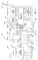
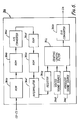
- Figure 1 is a block diagram showing an arrangement of a mobile telephone apparatus according to an embodiment of the present invention.
- mobile telephone apparatus 100 comprises antenna 200, radio unit 300, and telephone unit 400.
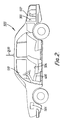
- antenna 200 is mounted on an outer body surface of automobile 500.
- Telephone unit 400 is mounted near driver's seat 504 inside automobile 500.
- Radio unit 300 mainly comprises radio section 310 for establishing a first and a second radio channel 600 with a base station (not shown) through antenna 200 and for exchanging signals therewith, radio unit controller 330 for controlling the overall operations of the apparatus, voice recognition/response circuit 350 for performing speech recognition and synthesis and for storing speech pattern signals, ID ROM 370 for storing ID (Identification Number) and telephone numbers, and power source 390 for supplying power from battery 506 (Fig. 2) mounted in the automobile to the above components through fuse 508.
- Telephone unit 400 mainly comprises handset controller 418 for controlling the overall operations of telephone unit 400 in response to instructions or the like from radio unit controller 330, key unit 430 for entering key inputs, display unit 450 for displaying numerical or alphabetical characters in response to the control of handset controller 418, switches 470 for performing various switching operations, and selectable audio input/output units 490 a or b for inputting or outputting an audible sound.
- Telephone unit 400 may be divided into main unit 400a and handset 400b.
- Microphone 494 may be a hands-free microphone 494 mounted on sun visor 510 or the like near driver's seat 504 and is connected to main unit 400a. Loudspeaker 492 may be mounted in main unit 400a.
- Handset controller 418, key unit 430, and display unit 450 are mounted in handset 400b.
- Handset microphone 466 and handset receiver 498 constitute audio input/output unit 490b of handset 400b.
- Each section of radio unit 300, main unit 400a, and handset 400b is supplied with power by way of a power line 1005 extending from power source 390 in radio unit 300.
- the opened or closed status of switches 470 is transmitted to power source 390 or radio unit controller 330 by way of line 1000 or line 1001 respectively.
- Control or command signals are transmitted between handset controller 418 and radio unit controller 330 by way of line 1002.
- Audio signals are transmitted by way of lines 1003.
- Radio unit controller 330 sends control signals to audio input/output unit 490a, b by way of lines 1004.
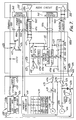
- Figure 3 is a block diagram showing a detailed arrangement of the radio unit of Fig. 1.
- radio section 310 comprises demodulator 312, modulator 314, and synthesizer 320.
- Demodulator 312 demodulates a radio signal received from the base station through radio channels 600, antenna 200, and duplexer 318. It should be noted that this signal includes audible sound signals and control signals.
- Modulator 314 modulates the audio and control signals and the like from audio controller 330 and generates transmission signals.
- Power amplifier 316 amplifies the transmission signals from modulator 314.
- the amplification of power amplifier 316 may be continuous or step-wise variable, e.g., 8-step variable.
- Duplexer 318 sends the signals received through radio channel 600 to demodulator 312 and the signals from modulator 314 and power amplifier 316 to antenna 200.
- Synthesizer 320 comprises a channel selection local oscillator and specifies a frequency from which signals are demodulated by demodulator 312 and a frequency to which signals are modulated by modulator 314. About 666 channels are available for synthesizer 320.
- Radio unit controller 330 comprises central processing unit (CPU) 331, oscillator/frequency divider 332, address decoder 333, ROM 334, RAM 335, radio controller 336, audio circuit 337, control signal processor 338, audio circuit controller 339, digital interface 340, power controller 341, and interrupt controller 342.
- Reference numeral 343 denotes a data bus; 344, an address bus; and 345, a control bus.
- CPU 331 controls the operations of radio unit controller 330.
- Oscillator/frequency divider 332 supplies clock signals to CPU 331 and divides the clock signals so as to supply appropriately frequency-divided pulses as timing pulses to each section of the mobile telephone apparatus requiring them.
- Address decoder 333 outputs predetermined operation signals to the components in response to instruction signals from CPU 331.
- ROM 334 stores various programs required for operation of CPU 331.
- RAM 335 stores various kinds of data during processing by CPU 331.
- Radio controller 336 controls radio section 310 in response to instructions from CPU 331. For example, radio controller 336 sends signals indicative of available frequencies to the synthesizer 320, signals indicative of an amplification level to power amplifier 316, and signals indicative of modulation parameters to modulator 314.
- Radio controller 336 receives a step-out signal from synthesizer 320 and output power detection signals from power amplifier 316 and forwards them to CPU 331, thereby preventing operation errors.
- Audio circuit 337 extracts control signals and audio signals from the received signals demodulated by demodulator 312 and supplies the control signals to control signal processor 338 and the audio signals to voice recognition/response circuit 350 and telephone unit 400. Audio circuit 337 also supplies the control signal from control signal processor 338 and audio signals from telephone set 400 and voice recognition/response circuit 350 to modulator 314. It should be noted that audio circuit 337 also arranges the wave form of the control signal to be sent to control signal processor 338 in a particular signal format and filters the control signal to be supplied to modulator 314. Control signal processor 338 acquires bit and frame synchronization with the control signal from audio circuit 337.
- control signal processor 338 converts the serial control signals including control data received from a base station into parallel signals and converts the parallel control data signals to be transmitted to a base station into serial signals.
- the control signals are sent to and from the base station via audio circuit 337.
- Audio circuit controller 339 controls audio circuit 337. For example, under the control of audio circuit controller 339, audio circuit 337 selectively applies the received signals from demodulator 312 to control signal processor 338, to voice recognition/response circuit 350, and to telephone unit 400 and selectively receives the signals from control signal processor 338, voice recognition/response circuit 350, or telephone unit 400.
- Digital interface 340 interfaces data communication between radio unit 300 and telephone unit 400.
- Power controller 341 controls power source 390. For example, power controller 341 sets a voltage supplied from battery 506 to power source 390 to a predetermined level. The voltage having the predetermined level is supplied to the respective components.
- Voice recognition/response circuit 350 comprises a voice recognition circuit for recognizing words spoken by a user, a speech synthesis circuit for synthesizing voice messages, a DTMF receiver for recognizing received DTMF signals, and a voice response circuit for reproducing a user's voice.
- Figure 4A is a block diagram of voice recognition circuit 350a, speech synthesis circuit 350b, and DTMF receiver circuit 350c of voice recognition/response circuit 350.
- Voice recognition circuit 350a comprises a high-pass filter 352 for eliminating high-frequency components of signal, amplifier 353 for amplifying the output signal of high-pass filter 352 responsive to an amplification control signal from CPU 331, automatic gain control (AGC) circuit 354 for controlling the output power of amplifier 353, attenuator 356 for attenuating the output signal of amplifier 353 responsive to an attenuator control signal from CPU 331, speech recognition LSI 357, RAM 358, latches 359 and 360, gate circuits 361 and 362, and address decoder 363.
- LSI as used in the specification refers to large scale integrated circuits; however, integration on such a scale is exemplary and may be replaced with developing technology.
- Voice recognition LSI 357 recognizes speech signals.
- RAM 358 stores data or a word to be recognized in voice recognition LSI 357.
- Latch 359 latches the amplification control signal, the attenuator control signal, chip enable signals CE1-CE4 to RAM 358. It also latches a registration signal and a read signal to voice recognition LSI 357, and a latch signal to latch 360, which are transmitted via address bus 344 and data bus 343 from CPU 331.
- IN/OUT 1,2 terminals of voice recognition LSI 357 are connected with data Bus 343 via gate circuits 361, 362.
- Latching in latches 359, 360 and gating in gate circuits 361, 362 are controlled by control signals transmitted via address decoder 363 by way of address bus 344 and control bus 345.
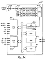
- Fig. 5A is a detailed block diagram of voice recognition LSI 357.
- speech recognition LSI 357 comprises two amplifiers 357a and 357b, four band-pass filters 357c, 357d, 357e, and 357f, multiplexer 357g, analog to digital (A/D) converter 357h, CPU 357i, ROM 357j, RAM 357k, CPU interface 357l, and RAM interface 357m.
- A/D analog to digital
- Amplifiers 357a and 357b amplify the input speech signal.
- the gain value of each of amplifiers 357a and 357b is, for example, 10.
- Band-pass filters 357c, 357d, 357e, and 357f filter the amplified speech signal.
- the center frequencies of band-pass filters 357c, 357d, 357e, and 357f are respectively 0.5 kHz, 1 kHz, 2 kHz, and 4 kHz.
- Multiplexer 357g multiplies the speech signal output filtered through band-pass filters 357c, 357d, 357e, and 357f.
- A/D converter 357h converts the multiplexed speech signal into a digital signal.
- CPU 357i controls the overall operations of voice recognition LSI 357.
- ROM 357j stores various kinds of programs to be required for the operation of CPU 357i.
- RAM 357k stores various kinds of data during control of CPU 357i.
- CPU interface 357 interfaces data communication with CPU 331 in radio unit controller 330.
- RAM interface 357m interfaces with RAM 358 (Fig. 4A).
- the sampled, quantized, coded speech signal supplied through amplifiers 357a and 357b, band-pass filters 357c, 357d, 357e, and 357f, multiplexer 357g, and A/D converter 357h are temporarily stored in RAM 357k. It should be noted that a portion of speech signal having a level over a predetermined value is identified as one speech pattern and detected by CPU 357i and thereby only speech pattern signal between the head position and the end position are stored in RAM 357K. A sampling rate at which A/D converter 357 h converts an analogue signal supplied thereto to a digital signal is fixed. Accordingly the number of data samples of one voice pattern stored in RAM 357k depends on the length of the voice pattern.
- CPU 357i extracts a predetermined number of data samples (i.e., 16) from the data samples of one voice pattern stored in RAM 357k by discriminating appropriately, so that the extracted data samples represent the voice pattern. In other words the voice patterns are normalized over time. Meanwhile, CPU 357i loads stored data from RAM 358 via RAM I/F 357m one voice pattern at a time. It should be noted that the stored data in RAM 358 corresponding to each voice pattern consists of the above-mentioned predetermined number of data samples. CPU 357i compares data samples of one voice pattern from RAM 357k with the corresponding data of one voice pattern from RAM 358 and calculates the sum of differences between them one voice pattern at a time speech pattern.
- a predetermined number of data samples i.e. 16
- CPU 357i After calculating the sum of difference for each voice pattern in RAM 358, CPU 357i determines which voice pattern in RAM 358 is the most similar to the voice pattern from RAM 357k, i.e., a voice pattern whose sum is the smallest is selected. And CPU 357i determines whether the sum of the selected one exceeds a predetermined value or not. If the sum of differences for the selected voice pattern one does not exceed the value, CPU 357i concludes that the voice pattern in RAM 358 is substantially identical to that in RAM 357k and sends a detection signal to CPU 331 via interrupt controller 342 and outputs a data code, which is an address data where the identical voice pattern is stored and corresponds to the recognized voice, from IN/OUT 1,2 terminals. Referring again to Fig. 4A, the data code is transmitted via gate circuits 361, 362 and by way of data bus 343 to CPU 331.
- Speech synthesis circuit 350b comprises speech synthesis LSI 364 for generating predetermined speech patterns on the basis of the data sent from CPU 331 in radio unit controller 330, latch 365, and amplifier 366 for amplifying the synthesized speech patterns.
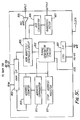
- Fig. 6 is a detailed block diagram of speech synthesis LSI 364.
- speech synthesis LSI 364 comprises ROM 364a indirectly addressed by a predetermined code, ROM 364b for storing speech parameters, parallel/serial (P/S) converter 364c for converting parallel signals to serial signals, RAM 364d for storing one-frame parameters, ROM 364e for storing nonlinear decoding parameters, i.e., pitch, noise, and amplitude, interpolator 364f for interpolating parameters every predetermined interval, register 364g for storing parameters and performing arithmetic operations, voiced sound source 364h, voiceless sound source 364i, grading digital filter 364j, and D/A converter 364k.
- P/S parallel/serial
- RAM 364d for storing one-frame parameters
- ROM 364e for storing nonlinear decoding parameters, i.e., pitch, noise, and amplitude
- interpolator 364f for interpolating parameters every predetermined interval
- register 364g for storing parameters and performing arithmetic
- DTMF receiver circuit 350c comprises high-pass filter 367 and DTMF receiver 368.
- DTMF receiver 368 receives a DTMF signal included in the speech signal through high-pass filter 367 and recognizes the two selected tones of the DTMF signal.
- Fig. 5B is a detailed block diagram of DTMF receiver 368.
- DTMF receiver 368 comprises filters 368a-g for filtering input signals to recognize the seven possible different tones of a DTMF signal, decoder 368h for decoding the output of filters 368a-g, and latch 368i for latching the output of decoder 368h responsive to a chip select signal sent from CPU 331 by way of control bus 345 and for outputting a data code corresponding to a detected DTMF signal to CPU 331 by way of data bus 343 after sending a detection signal to CPU 331 via interrupt controller 342.
- Fig. 4B is a block diagram of voice response circuit 350d in voice recognition/response circuit 350.
- the voice response circuit comprises address decoder 701 for decoding address signals A0-A3 via address bus 344 and control signals WR and RD via control bus 343 from CPU 331, latches 702-704 for temporarily storing signals from address decoder 701 and for providing these signals as 'P0-P3', 'RD', 'WR', to voice storage/reproduction LSI 710.
- RAM 708 stores voice pattern data of user spoken words which may be reproduced in the below discussed selective reception mode when a caller spoken password matches a stored one according to voice storage/reproduction LSI 710 writing and reading data samples of the voice pattern.
- Amplifier 711 amplifies the output of voice storage/reproduction LSI 710.
- Amplifier 712 amplifies signals applied to voice storage/reproduction LSI 710.
- Filter circuit 713 filters the output of amplifier 712, and amplifier 714 amplifies the output of filter circuit 713 and provides the amplified output to voice storage/reproduction LSI 710.
- the output of amplifier 353 (Fig. 4A) is applied to the input of amplifier 712.
- Fig. 5C is a block diagram of the voice storage/reproduction LSI 710.
- a signal WR and an address signal P0-P3 indicative of locations for voice data to be stored are sent from CPU 331 to CPU I/F 801. Responsive to these signals, timing generator control circuit 802 accesses the locations addressed by the address signal in RAM 708 (Fig. 4B) via RAM I/F 803.
- a voice signal applied to INPUT is amplified at MIC AMP 804 and analyzed by adaptive delta modulation (ADM) processing in ADM analysis/synthesis circuit 805. An analyzed voice signal is sequentially sent to the RAM 708 and stored in the addressed locations.
- ADM adaptive delta modulation
- timing generator control circuit 802 sets the end address, which is larger than the transmitted address by a predetermined value, in stop address register 811 and accesses the locations addressed by the address (the data code) in RAM 708 via RAM I/F 803. Data in the accessed location are loaded into ADM analysis/synthesis circuit 805 via RAM I/F 803. ADM analysis/synthesis circuit 805 synthesizes a digital speech signal in response to the loaded data. The output of ADM analysis/synthesis circuit 805 is applied to D/A converter 806 and converted into an analogue voice signal therein.
- the analogue signal is output via bandpass filter 807.
- the address of the location accessed in RAM 708 is contiguously incremented by address counter 813 until it equals the end address set in stop address register 811.
- voice data in RAM 708 may be sequentially loaded into speech storage/reproduction LSI 710 and a voice signal may be reproduced.
- Figure 7 is a detailed view of the telephone unit 400 described above.
- main unit 400a mainly comprises audio controller 410, speech input/output unit 490a, and switch unit 470.
- Audio controller 410 mainly comprises balanced to unbalanced line B/U converter 411, U/B converter 412, amplifiers 413 and 414, echo canceler 415, and switches 416 and 417.
- Speech input/output unit 490a comprises hands-free microphone 494 and loudspeaker 492.
- Switch unit 470 comprises hook switch 472 and on/off switch 474.
- Balanced line to unbalanced line (B/U) converter 411 converts the speech signals sent from audio circuit 337 in radio unit 300 through balanced line 411a into signals on unbalanced line 411b.
- the speech signal converted into the signals on unbalanced line 411b are amplified by amplifier 413 and output via loudspeaker 492. Since the speech signal outputs from the audio circuit in the radio unit are the signals on the unbalanced line, the speech signals are converted into the signals on the balanced line by U/B converter 337a arranged in the immediate output stage of the audio circuit 337.
- the speech signal inputted at hands-free microphone 494, amplified by amplifier 414, and appearing on unbalanced line 412a are converted into signals on balanced line 412b.
- the speech signals converted into the signals on balanced line 412b are sent to audio circuit 337 through balanced line 412b.
- the speech signal inputs to audio circuit 337 in radio unit 300 are signals on the unbalanced line, so that the speech signals are converted into signals on the unbalanced line by B/U converter 337b arranged in the immediate output stage of audio circuit 337.
- Echo canceler 415 comprises attenuator 415a for attenuating the speech signal input from B/U converter 411 to amplifier 413, attenuation controller 415b for controlling an attenuation level of attenuator 415a, attenuator 415c for attenuating the speech signal input from the amplifier 414 to U/B converter 412, attenuation controller 415d for controlling an attenuation level of attenuator 415c, and control amount calculator 415e for calculating control amounts of attenuation controllers 415b and 415d on the basis of the speech signal on the respective lines.
- Switch 416 is operated to determine whether the speech signal from B/U converter 411 is to be output from loudspeaker 492.
- Switch 417 is operated to determine whether the speech signal from hand-free microphone 494 is sent to audio circuit 337 in radio unit 300. The operations of switches 416 and 417 are performed on the basis of control signals output from radio unit controller 330.
- Hook switch 472 of switch unit 470 detects the on- or off-hook state of handset 400b. The detected signal is sent to radio unit controller 330 in radio unit 300.
- On/off switch 474 performs overall ON/OFF operation of mobile telephone apparatus 100. A switching signal from switch 474 is sent to radio unit controller 330 in radio unit 300.
- Handset 400b comprises handset controller 418, display unit 450, key unit 430, and speech input/output unit 490b.
- Display unit 450 comprises liquid crystal display 452 and LCD driver 454.
- Key unit 430 comprises a plurality of keys which may be arranged in a key pad.
- Speech input/output unit 490b comprises amplifiers 419a, 419b, and 419c, an attenuator 420, U/B converter 421, speech switch unit 422c, and switches 423 and 424, handset microphone 496, and handset receiver 498.
- Handset controller 418 controls the overall operations of handset 400b on the basis of control signals sent from radio unit controller 330 in radio unit 300.
- handset controller 418 sends control signals or the like input from key unit 430 to radio unit controller 330 in radio unit 300.
- Amplifiers 419a and 419b amplify the speech signal sent from the B/U converter 411 in main unit 400a.
- Attenuator 420 attenuates the speech signals amplified by amplifiers 419a and 419b.
- the speech signal output through amplifier 419a, attenuator 420, and amplifier 419b is output from handset receiver 498.
- Amplifier 419c amplifies the speech signal input from handset microphone 496.
- U/B converter 421 converts the amplified speech signals on unbalanced line 421a into signals on balanced line 421b.
- the speech signal converted into the signal on balanced line 421b is sent to audio circuit 337 through balanced line 421b and balanced line 421c.
- Switch 423 is operated to determine whether the speech signal from B/U converter 411 is to be output from handset receiver 498.
- Switch 424 is operated to determine whether the speech signal from handset microphone 496 is to be output to audio circuit 337 in radio unit 300.
- the operations of switches 423 and 424 are performed on the basis of the control signal output from handset controller 418 and are interlocked with switches 416 and 417 in main unit 400a.
- Switches 416, 417, 423 and 424 are turned off.
- switch 416 is turned on, and switches 417, 423 and 424 are turned off.
- switches 416 and 417 are turned on, and switches 423 and 424 are turned off.
- Speech switch unit 422 comprises level detector 422a, OR gate 422b, and switch 422c.
- Level detector 422a detects a signal level of speech signal input to handset microphone 496. If the signal level is less than a predetermined value, level detector 422a generates a signal of level "L".
- level detector 422a if the signal level exceeds the predetermined value, level detector 422a generates a signal of level "H".
- OR gate 422b receives an ouput signal L or H from level detector 422a and a predetermined control signal output from controller 418 and generates an OR signal.
- Switch 422c is turned on in response to the signal of level "L” from OR gate 422b, and speech signal line 421a is grounded. The speech signal from handset microphone 496 is not transmitted to audio circuit 337, and handset microphone 496 is set in the OFF state.
- Switch 422c is turned off in response to the signal of level "H" from the OR gate 422b, and the handset microphone 496 is set in the ON state.
- the control signal input from controller 418 to one input terminal of OR gate 422b is set at level “L” in the standby mode and during normal communication and at level "H” in the voice recognition mode allowing voice dialing. Therefore, when no voice is input to handset microphone 496 in the busy state, handset microphone 496 is set in the OFF state. Therefore, noise in the automobile 500 is not sent to the other party and comfortable communication can be achieved.
- Liquid crystal display 452 comprises a numerical display element 452a having several display digit positions and display element 452b for displaying various functions.
- LCD driver 454 drives liquid crystal display 452 under the control of handset controller 418 to display numerical or alphabetical characters.
- Key unit 430 includes keys including at least numerical keys “0” to “9” as well as function keys “*”, “#”, “SND”, “STO”, “END”, “RCL”, “FCN”, “CLR”, “EMR”, “MUTE”, and “TONE”. When a desired key is depressed, the depressed key is detected by handset controller 418.
- On/OFF switch 474 in switch unit 470 of telephone unit 400 When On/OFF switch 474 in switch unit 470 of telephone unit 400 is turned on, the respective components are powered by power source 390 (step 1101).
- Fig. 9 is a detailed flow chart for explaining the initial radio channel connection operation after the power supply is turned on.
- radio controller 336 in radio unit controller 330 controls synthesizer 320 to change the frequency of output therefrom.
- a predetermined range of control channels (referred to as D channels hereinafter) is scanned in demodulator 312 to obtain the information indicative of electric field intensity of the received signals over each channel (step 1301).
- the channel having the strongest electric field intensity is selected from the D channels and the apparatus is ready for receiving signals through the D channel having the strongest electric field intensity. In this case, information of a channel having the second strongest intensity is also obtained.
- audio circuit controller 339 controls switching section 337a in audio circuit 337 so that the output of demodulator 312 is applied to the input of control signal processor 338 and the output of control signal processor 338 is applied to the input of modulator 314 as shown in Fig. 10 (connection A in Fig. 10).
- Control signal processor 338 performs bit and frame synchronization operations on signals received through the selected D channel (step 1302). Thereby a communication link has been established between the mobile telephone and a base station. System information is then detected in signals through this D channel at control signal processor 338 (step 1303) and sent to CPU 331.
- the system information includes a range of frequency channels (referred to as P channels hereinafter) to be scanned next.
- the demodulator scans the D channels again (step 1301).
- Fig. 11 is a detailed flow chart for explaining P channel connection after initialization.
- radio controller 336 controls synthesizer 320 to change the frequency of output therefrom so that P channels are scanned in demodulator 312 (step 1401) to obtain the information indicative of electric field intensity of the received signals.
- the apparatus is ready for receiving information though the P channel of the strongest electric field intensity. In this case, information of the P channel having the second strongest intensity is also obtained.
- Control signal processor 338 performs bit and frame synchronization operations on signals received through the P channel which has the strongest electric field intensity (step 1402). After acquiring the synchronization, control signal processor 338 determines whether the following information is addressed to the apparatus by comparing an address code included in the following information with an ID code which has been read from ID ROM 370 via CPU 331 in advance. If it is addressed to the apparatus, control signal processor 338 obtains system information from the following information signals and sends it to CPU 331. This radio channel communication using P channels is also a communication link between the mobile telephone and the base station.
- step 1404 If the word synchronization or system information reception is not performed within a predetermined period of time, the operation similar to the one described above is performed for the P channel having the second strongest intensity (step 1404). In this case, when word synchronization or system information reception is again not performed within the predetermined period of time, initialization is resumed (step 1102). If position information is not obtained from system information, initialization is also resumed (step 1102).
- connection control operations set the apparatus in the reception standby state (step 1104).
- an acknowledge signal is sent back through a predetermined channel (step 1105).
- scanning of control channels (referred to as A channels hereinafter) for receiving control signals from the base station is performed in the same manner as for D and P channels.
- a frequency range of A channels is designated in the system information addressed to the apparatus which is obtained from signals transmitted via the P channel.
- radio controller 336 controls synthesizer 320 to change the frequency of output therefrom so that A channels are scanned in demodulator 312 to obtain the information indicative of electric field intensity of the received signal.
- the apparatus is then ready for receiving information through the A channels having the strongest electric field intensity.
- control signal processor 338 performs bit and frame synchronization operations, i.e., word synchronization.
- This radio channel communication using A channels is also a communication link between the mobile telephone and the base station.
- the channels are switched to the designated speech channels: a forward channel for transmitting audio signals to the base station and a backward channel for receiving audio signals from the calling apparatus via the base station.
- the apparatus then waits to receive a ringing signal in the backward channel (step 1106).
- the on-hook state is set in the reception standby state, the reception mode of the speech channels is cancelled (step 1107), and the transmission function is disabled (step 1108).
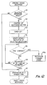
- step 1111 When the ringing signal is received, the operation of the apparatus proceeds to selective reception (step 1111). The operations of selective reception will be described in detail in reference to Fig. 12, wherein decision box 111 indicates entry into a selective reception mode.
- the ringing signal included in the signal received through the backward channel is detected by control signal processor 338.
- control signal processor 338 Upon the detection of the ringing signal, control signal processor 338 sends a detection signal to CPU 331.
- CPU 331 determines whether the selective reception mode has been set or not (step 1111). This selective reception mode may be set in response to a certain order of key input, for example FCN 2 1 * entered at key unit 430.
- handset controller 418 sends a mode set signal to CPU 331.
- CPU 331 sets a mode set flag 335a in RAM 335. Therefore whether the selective reception mode is set or not is determined by checking the mode set flag.
- CPU 331 sends a first connection signal to audio circuit controller 339. Responsive to the first connection signal, audio circuit controller 339 controls switching section 337a in audio circuit 337 so that the output of demodulator 312 is applied to the input of voice recognition/response circuit 350 and the output of recognition/response circuit 350 is applied to the input of modulator 314 (connection B in Fig. 10) as shown in Fig. 10 (step 112).
- CPU 331 sets an internal timer thereof to zero (step 113).
- the internal timer is a free running timer clocked in response to a clock pulse signal supplied from oscillator/frequency divider 332..
- CPU 331 accesses speech synthesis LSI by sending a chip select signal via buses 343-345 so that a predetermined voice message, for example, "Now call receptions are limited. Please input your ID code or speak your password if you know it" is generated from speech synthesis LSI 364.
- a predetermined voice message for example, "Now call receptions are limited. Please input your ID code or speak your password if you know it" is generated from speech synthesis LSI 364.
- the generated voice messages are applied to modulator 314 via audio circuit 337 and transmitted from antenna 200 through the forward channel (step 114).
- the voice messages are transmitted to a calling telephone apparatus via a base station by way of the forward channel
- CPU 331 sends chip select signals to voice recognition LSI 357 and DTMF receiver 368.
- a calling party responsive to the voice message may input a predetermined ID code, for example, consisting of a 4 digit number or speak a predetermined password, for example a person's name, if the calling party knows it.
- the received signals continue to be applied to voice recognition/response circuit 350 by way of demodulator 312 and audio circuit 337.
- voice recognition/response circuit 350 the received signal is input to voice recognition LSI 357 via high-pass filter 352, amplifier 353, and attenuator 356 and is also input to DTMF receiver 368 via filter 367.
- step 115 If the time measured by the internal timer of CPU 331 has expired (step 115) without detecting the ID code or the password from the calling party, the operation of CPU 331 is interrupted by the internal timer and CPU 331 returns to the reception standby state (step 1104 Fig. 8). Then CPU 331 sends a second connection signal to audio circuit controller 339. Responsive to the second connection signal, audio circuit controller 339 controls switching section 337a in audio circuit 337 so that demodulator 312 and modulator 314 are re-connected to control signal processor 338.
- CPU 331 receives a data code corresponding to a recognized password or a detected ID code and checks whether it is a call to be indicated to the user or not by comparing the data code with the stored data code which is read from RAM 335. If it is determined that the reception of the incoming call is to be indicated, CPU 331 sends a third control signal to audio circuit controller 339.
- audio circuit controller 339 controls switching section 337b in audio circuit 337 so that a pulse signal of a predetermined frequency for generating a ringer tone from oscillator/frequency divider 332 is applied to speaker 492 via line 1003. Accordingly, a ringer tone is sounded at speaker 492 (step 117). Then the operation of the apparatus proceeds to a step of waiting for the user's response (step 1109; Fig-8).
- handset controller 418 detects the key operation and sends a control signal of "SEND" key operation to CPU 331 via digital interface 340 by way of lines 1002. Also in the event that the user takes handset 400b off-hook, the information of the closed state of hook switch 472 is transmitted to CPU 331 via digital interface 340 by way of line 1001. Responsive to the off-hook control signal or the information, CPU 331 sends a fourth connection signal to audio circuit controller 339.
- audio circuit controller 339 controls switching sections 337a and 337b in audio circuit 337 so that demodulator 312 and modulator 314 are connected to audio input/output unit 490 by way of line 1003 (connection C in Fig. 10). Accordingly the user may communicate with the calling party by using hands-free microphone 494 and loudspeaker 492 or handset microphone 466 and handset receiver 498.
- the acknowledge signal sending state step 1104
- a communication enable state step 1110
- the transmission function is disabled (step 1108).
- initialization is resumed (step 1102).
- a ringer tone is sounded when the DTMF signal indicates an ID code or the password voice message is detected in the above-described embodiment, there are various modifications of indicating means.
- a ringer tone it may be a beep tone beeping for a short time, for example, one second. Otherwise some message may be displayed with or without sounding a tone.
- CPU 339 sends a display signal to handset controller 418. Responsive to the display signal, handset controller 418 controls display unit so that a predetermined message, for example, "A CALL IS RECEIVED" is displayed.
- CPU 331 sends the detected ID code, which matched the stored one, with the display signal to handset controller 418. Responsive to the display signal, handset controller 418 controls display unit 450 so that numerical or alphabetical characters corresponding to the detected ID code are displayed. According to this modification, the user may identify who is a caller by checking the displayed characters. Furthermore, on the basis of the recognized password, one or more voices corresponding to the password may be generated.
- CPU 331 sends the data code corresponding to the recognized password, which also matched with a stored one, to voice response circuit 350d, voice recognition/response circuit 350 via data bus 343 after sending a chip select signal for selecting speech storage/reproduction LSI 710 with the RD signal via control bus 345
- CPU 331 then sends a fifth connection signal to audio circuit controller 339.
- audio circuit controller 339 controls switching section 337a in audio circuit 337 so that the output of voice recognition/response circuit 350 is connected with line 1003 to speaker 492 (connection D in Fig. 10).
- voice response circuit 350d outputs an analogue voice signal, which has been stored in advance by the user.
- the signal is transmitted to speaker 492 by way of line 1003. Accordingly, a voice corresponding to a password spoken by a caller is generated from speaker 492. It should be noted that voice storage in RAM 708 in advance may be accomplished by the user of the apparatus or any person who knows the password. After generating the voice, a line connection in switching section 337a of audio circuit 337 is switched to connection C from connection D.
- the present invention may be integrated into the automobile.
- voice synthesis means for generating sent belt warning messages may be applied for messages of the mobile telephone apparatus.
- the visual display 450 may be integrated into the dashboard and so on.
- radio unit 300 and antenna 200 are incorporated into a casing of main unit 400a of telephone unit 400, and thereby the telephone unit including radio unit and antenna is capable of being carried by a user.
- telephone unit 400, radio unit 300, and antenna 200 are combined together in a single casing. The essential features of this invention are applicable to all such cases.
- the scope of this invention is not limited to the application in a radio telephone capable of being connected to a land-line telephone such as a cellular radio telephone in a cellular radio system but any application of a radio telephone using radio channels falls within the scope of this invention.
Landscapes
- Engineering & Computer Science (AREA)
- Signal Processing (AREA)
- Computer Security & Cryptography (AREA)
- Computer Networks & Wireless Communication (AREA)
- Mobile Radio Communication Systems (AREA)
Claims (13)
- Appareil radio-téléphonique qui comprend :
des moyens de réception (300) pour recevoir les signaux émis par un ou plusieurs canaux radio ;
des premiers moyens de détection (330) répondant auxdits moyens de réception (300) pour détecter une première séquence de signaux prédéterminée indiquant l'arrivée d'un appel pour l'appareil radio-téléphonique ;
des seconds moyens de détection (350a, 350c) pour détecter une seconde séquence prédéterminée de signaux émanant d'un appareil qui appelle et est transmise en association avec ladite première séquence de signaux prédéterminée ; et
des moyens d'indication (450) pour fournir à l'usager de l'appareil une indication signalant la réception d'un appel,
caractérisé en ce que l'appareil comprend, en outre, des moyens pour établir un mode de réception sélectif, et en ce qu'il comprend, en outre, des moyens pour établir un mode de réception sélectif, et où les moyens d'indication (450) sont adaptés à fournir à l'usager une indication en réponse à la détection de la première séquence prédéterminée de signaux quand ledit appareil n'est pas réglé pour opérer dans un mode de réception sélectif, et pour fournir cette indication à l'usager en réponse à la détection, à la fois, de la première séquence de signaux prédéterminée et de la seconde séquence de signaux prédéterminée quand ledit appareil est réglé pour opérer dans le mode de réception sélectif. - Appareil selon la revendication 1, caractérisé en ce que, quand ledit appareil est réglé pour opérer dans le mode de réception sélectif, ledit appareil, après détection de ladite première séquence de signaux, est adapté à envoyer à l'appareil qui appelle, un signal qui requiert la seconde séquence de signaux prédéterminée.
- Appareil selon la revendication 1 ou 2, caractérisé en ce que lesdits moyens de réception comprennent des moyens pour détecter si un ou plusieurs canaux radio sont disponibles.
- Appareil selon la revendication 3, caractérisé en ce que lesdits moyens de réception comprennent encore des moyens pour établir un ou plusieurs canaux radio en réponse à la détection de la disponibilité des canaux.
- Appareil selon la revendication 1, 2, 3 ou 4, caractérisé en ce que les premiers moyens de détection comprennent des moyens pour détecter un signal incident pourvu d'une adresse concernant l'appareil radio-téléphonique.
- Appareil selon la revendication 5, caractérisé en ce que lesdits moyens de détection de signaux comprennent une mémoire pour conserver un ou plusieurs numéros d'identification et des moyens de comparaison pour comparer le ou chaque numéro d'identification avec ladite adresse.
- Appareil selon l'une quelconque des revendications précédentes, caractérisé en ce que ledit appareil comprend, en outre, des troisièmes moyens de détection pour détecter un signal de désignation de canal reçu conjointement avec lesdits signaux incidents et des moyens d'établissement qui, en réponse audit signal de désignation de canal, établissent une ou plusieurs artères de communication avec l'appareil qui appelle.
- Appareil selon la revendication 7, caractérisé en ce que la seconde séquence de signaux prédéterminée est reçue par une ou plusieurs lignes de communication établies.
- Appareil selon la revendication 7 ou 8, caractérisé en ce que ledit appareil comprend encore des moyens pour rétablir une ou plusieurs lignes de communication pour communiquer avec l'appareil qui appelle quand lesdits seconds moyens de détection ne détectent pas ladite seconde séquence prédéterminée de signaux dans les limites d'une période de temps prédéterminée.
- Appareil selon l'une quelconque des revendications précédentes, caractérisé en ce que lesdits seconds moyens de détection comprennent des moyens pour décoder les signaux multifréquences à deux tonalités et pour fournir des données d'identification d'adresse, une mémoire pour conserver une ou plusieurs données d'identification, des moyens de comparaison pour comparer les données d'identification d'adresse décodés avec les données d'identification conservées dans ladite mémoire, et des moyens de génération pour générer un signal de détection quand la donnée d'identification d'adresse décodée est identique à l'une desdites données d'identification conservées.
- Appareil selon l'une quelconque des revendications précédentes 1 à 9, caractérisé en ce que les seconds moyens de détection comprennent des moyens de reconnaissance vocale pour reconnaître des signaux vocaux, des moyens pour décoder des signaux à deux tonalités et à fréquences multiples et pour générer un signal de détection quand, soit lesdits moyens de reconnaissance vocale, soit lesdits moyens de décodage de signaux détectent ladite seconde séquence de signaux prédéterminée et lesdits moyens d'indication indiquent la réception d'un appel en réponse audit signal de détection.
- Procédé pour recevoir, sur un appareil récepteur, un appel venant d'un appareil appelant par radio-téléphonie, procédé qui consiste :
à recevoir des signaux émis par un ou plusieurs canaux radio ;
à détecter une première séquence de signaux prédéterminée représentative d'un appel arrivant audit appareil récepteur ;
à détecter une seconde séquence prédéterminée de signaux émanant dudit appareil qui appelle et qui est transmise conjointement avec ladite première séquence prédéterminée de signaux ; et
à fournir à un usager de l'appareil de réception une indication signalant la réception d'un appel, caractérisé en ce que l'usager reçoit ladite indication en réponse à la détection de la première séquence de signaux quand ledit appareil récepteur n'est pas préparé pour opérer dans un mode de réception sélectif, l'usager étant aussi pourvu de l'indication en réponse à la réception de ladite première séquence de signaux prédéterminée et de la seconde séquence de signaux prédéterminée, alors que ledit appareil récepteur est réglé pour opérer dans le mode de réception sélectif. - Procédé selon la revendication 12, caractérisé en ce que quand ledit appareil récepteur est préparé pour opérer dans le mode de réception sélectif dudit appareil récepteur, ledit appareil récepteur, après avoir détecté ladite première séquence de signaux prédéterminée, envoie vers l'appareil qui appelle, un signal demandant la seconde séquence prédéterminée de signaux.
Applications Claiming Priority (2)
| Application Number | Priority Date | Filing Date | Title |
|---|---|---|---|
| JP302508/87 | 1987-11-30 | ||
| JP62302508A JPH01143529A (ja) | 1987-11-30 | 1987-11-30 | 無線電話装置 |
Publications (3)
| Publication Number | Publication Date |
|---|---|
| EP0319210A2 EP0319210A2 (fr) | 1989-06-07 |
| EP0319210A3 EP0319210A3 (en) | 1990-09-26 |
| EP0319210B1 true EP0319210B1 (fr) | 1994-01-12 |
Family
ID=17909808
Family Applications (1)
| Application Number | Title | Priority Date | Filing Date |
|---|---|---|---|
| EP88311195A Expired - Lifetime EP0319210B1 (fr) | 1987-11-30 | 1988-11-25 | Appareil radio-téléphonique |
Country Status (6)
| Country | Link |
|---|---|
| US (1) | US4998291A (fr) |
| EP (1) | EP0319210B1 (fr) |
| JP (1) | JPH01143529A (fr) |
| KR (1) | KR960003840B1 (fr) |
| CA (1) | CA1300687C (fr) |
| DE (1) | DE3887111T2 (fr) |
Families Citing this family (49)
| Publication number | Priority date | Publication date | Assignee | Title |
|---|---|---|---|---|
| USRE37618E1 (en) | 1987-07-24 | 2002-04-02 | Richard J. Helferich | Analog/digital data storage system |
| USRE34976E (en) * | 1987-07-24 | 1995-06-20 | Richard J. Helferich | Analog/digital voice storage cellular telephone |
| US5146538A (en) * | 1989-08-31 | 1992-09-08 | Motorola, Inc. | Communication system and method with voice steering |
| FR2652221A1 (fr) * | 1989-09-15 | 1991-03-22 | Parise Corinne | Adaptateur pour le raccordement d'appareils peritelephoniques aux telephones de voiture. |
| US5553125A (en) * | 1991-01-11 | 1996-09-03 | Nokia Mobile Phones (U.K.) Limited | Telephone apparatus with calling line identification |
| US5155689A (en) * | 1991-01-17 | 1992-10-13 | By-Word Technologies, Inc. | Vehicle locating and communicating method and apparatus |
| US5734981A (en) * | 1991-01-17 | 1998-03-31 | Highwaymaster Communications, Inc. | Method and apparatus for call delivery to a mobile unit |
| DE69225084T2 (de) * | 1991-03-06 | 1998-11-12 | Nokia Mobile Phones Uk | Tragbares Telefon |
| US5208848A (en) * | 1991-08-26 | 1993-05-04 | At&T Bell Laboratories | Telecommunications call processing |
| US5454027A (en) * | 1992-01-27 | 1995-09-26 | Hm Holding Corporation | Phantom mobile identification number method and apparatus |
| US6295449B1 (en) | 1992-01-27 | 2001-09-25 | @Track Communications, Inc. | Data messaging in a communications network using a feature request |
| US5539810A (en) | 1992-01-27 | 1996-07-23 | Highwaymaster Communications, Inc. | Data messaging in a communications network |
| US6009330A (en) * | 1992-01-27 | 1999-12-28 | Highwaymaster Communications, Inc. | Method and apparatus for call delivery to a mobile unit |
| US5559860A (en) * | 1992-06-11 | 1996-09-24 | Sony Corporation | User selectable response to an incoming call at a mobile station |
| NL9201577A (nl) * | 1992-09-10 | 1994-04-05 | Ericsson Business Mobile Netwo | Telefoonsysteem met verschillende belpatronen. |
| FI93159C (fi) * | 1992-09-23 | 1995-02-27 | Nokia Mobile Phones Ltd | Menetelmä radiopuhelimen radiotaajuusvahvistimen ohjaamiseksi ja menetelmän mukainen ohjausjärjestelmä |
| EP0660571A1 (fr) * | 1993-06-15 | 1995-06-28 | Texas Instruments Incorporated | Interception automatique d'appel pour des répondeurs téléphoniques et des téléphones intelligents |
| US6324412B1 (en) | 1994-06-17 | 2001-11-27 | Nokia Mobile Phones, Ltd. | Telephone and module having a pin for providing temperature information and generating a silent alarm |
| JP2914425B2 (ja) * | 1994-12-27 | 1999-06-28 | 日本電気株式会社 | 自動電源制御機能付き携帯電話機 |
| IL112927A (en) * | 1995-03-07 | 1998-07-15 | Powerspectrum Technology Ltd | An appointment unit for use in a multi-approach communication system |
| US5699275A (en) * | 1995-04-12 | 1997-12-16 | Highwaymaster Communications, Inc. | System and method for remote patching of operating code located in a mobile unit |
| US5694322A (en) * | 1995-05-09 | 1997-12-02 | Highwaymaster Communications, Inc. | Method and apparatus for determining tax of a vehicle |
| US5651055A (en) * | 1995-06-29 | 1997-07-22 | Lucent Technologies Inc. | Digital secretary |
| DE19525530C2 (de) * | 1995-07-13 | 1998-03-12 | Grundig Ag | Verfahren und Schaltungsanordnung zur anruferindividuellen Signalisierung eines ankommenden Rufes durch eine Teilnehmereinrichtung |
| US5790647A (en) * | 1995-12-18 | 1998-08-04 | Ericsson, Inc. | Subscriber feature services in a telecommunications system |
| KR0169421B1 (ko) * | 1995-12-30 | 1999-02-01 | 김광호 | 간이전자교환장치의 전원절약 제어 방법 |
| FI102711B1 (fi) * | 1996-02-23 | 1999-01-29 | Nokia Mobile Phones Ltd | Puhelimen soittoäänen määrittely |
| JPH1051349A (ja) * | 1996-08-01 | 1998-02-20 | Nec Corp | 携帯用通信機 |
| US5845219A (en) * | 1996-09-04 | 1998-12-01 | Nokia Mobile Phones Limited | Mobile station having priority call alerting function during silent service mode |
| US6324592B1 (en) * | 1997-02-25 | 2001-11-27 | Keystone Aerospace | Apparatus and method for a mobile computer architecture and input/output management system |
| NL1005601C2 (nl) * | 1997-03-21 | 1998-09-22 | Koninkl Kpn Nv | Telecommunicatiesysteem. |
| FR2768281B1 (fr) * | 1997-09-10 | 2000-07-07 | Siemens Automotive Sa | Procede et dispositif de commande d'une unite de telephonie mise en place dans un vehicule automobile |
| US6349222B1 (en) * | 1999-02-01 | 2002-02-19 | Qualcomm Incorporated | Voice activated mobile telephone call answerer |
| JP2000244625A (ja) * | 1999-02-23 | 2000-09-08 | Nec Saitama Ltd | 携帯電話機における音声認識起動方法及び音声認識携帯電話装置 |
| US6236373B1 (en) * | 1999-09-15 | 2001-05-22 | Humentech 21 Company | Vehicle sun visor with radio antenna |
| JP2003199168A (ja) * | 2001-12-28 | 2003-07-11 | Nec Corp | 外部機器からの発信可能な電話装置 |
| EP1326411A1 (fr) * | 2002-01-07 | 2003-07-09 | Lucent Technologies Inc. | Appareil et procédé de télécommunication pour distinguer des types d'appels téléphoniques incidents |
| US20050153661A1 (en) * | 2004-01-09 | 2005-07-14 | Beck Stephen C. | Toy radio telephones |
| CN1319359C (zh) | 2004-06-07 | 2007-05-30 | 华为技术有限公司 | 一种来话接入方法 |
| US20070038351A1 (en) * | 2005-08-15 | 2007-02-15 | Larschan Bradley R | Driver activity and vehicle operation logging and reporting |
| US20070038338A1 (en) * | 2005-08-15 | 2007-02-15 | Larschan Bradley R | Driver activity and vehicle operation logging and reporting |
| US8626377B2 (en) | 2005-08-15 | 2014-01-07 | Innovative Global Systems, Llc | Method for data communication between a vehicle and fuel pump |
| US9818120B2 (en) | 2015-02-20 | 2017-11-14 | Innovative Global Systems, Llc | Automated at-the-pump system and method for managing vehicle fuel purchases |
| US20070038353A1 (en) * | 2005-08-15 | 2007-02-15 | Larschan Bradley R | Driver activity and vehicle operation logging and reporting |
| US7117075B1 (en) | 2005-08-15 | 2006-10-03 | Report On Board Llc | Driver activity and vehicle operation logging and reporting |
| US7707661B2 (en) * | 2006-03-13 | 2010-05-04 | David Issachar | Tissue and toilet seat-cover sanitary paper |
| US9388271B2 (en) * | 2009-03-30 | 2016-07-12 | Sanyo Chemical Industries, Ltd. | Polyoxyalkylene polyol or monool and polyurethane resin |
| US8831555B2 (en) * | 2009-04-03 | 2014-09-09 | Qualcomm Incorporated | Reestablishment procedure for an emergency call |
| US11584515B2 (en) | 2020-04-17 | 2023-02-21 | Goodrich Corporation | Tripod landing gear assembly |
Citations (1)
| Publication number | Priority date | Publication date | Assignee | Title |
|---|---|---|---|---|
| US4266098A (en) * | 1978-11-03 | 1981-05-05 | Novak Albert P | Device to automatically screen incoming telephone calls, determine the identity of the caller and process the call accordingly |
Family Cites Families (10)
| Publication number | Priority date | Publication date | Assignee | Title |
|---|---|---|---|---|
| JPS58138134A (ja) * | 1982-02-12 | 1983-08-16 | Nissan Motor Co Ltd | 自動車電話装置 |
| US4475010A (en) * | 1983-05-05 | 1984-10-02 | At&T Bell Laboratories | High density cellular mobile radio communications |
| US4796291A (en) * | 1983-10-28 | 1989-01-03 | Nec Corporation | Mobile radio communications system |
| JPS60201751A (ja) * | 1984-03-27 | 1985-10-12 | Nec Corp | 音声入出力装置 |
| JPS60223340A (ja) * | 1984-04-20 | 1985-11-07 | Sony Corp | コ−ドレステレホン |
| US4611098A (en) * | 1984-12-04 | 1986-09-09 | Giorgio Paul J | Coded telephone access system |
| JPS61212930A (ja) * | 1985-03-19 | 1986-09-20 | Oki Electric Ind Co Ltd | 広域移動通信システムにおける移動機 |
| JPS61274531A (ja) * | 1985-05-30 | 1986-12-04 | Nec Corp | チヤネル選択方式 |
| JPH0624337B2 (ja) * | 1985-09-30 | 1994-03-30 | 日本電信電話株式会社 | 無線電話装置の着呼信号送出方式 |
| JPH0738744B2 (ja) * | 1987-03-23 | 1995-04-26 | 株式会社東芝 | 無線電話装置 |
-
1987
- 1987-11-30 JP JP62302508A patent/JPH01143529A/ja active Pending
-
1988
- 1988-11-23 US US07/275,312 patent/US4998291A/en not_active Expired - Lifetime
- 1988-11-25 CA CA000584097A patent/CA1300687C/fr not_active Expired - Lifetime
- 1988-11-25 DE DE88311195T patent/DE3887111T2/de not_active Expired - Lifetime
- 1988-11-25 EP EP88311195A patent/EP0319210B1/fr not_active Expired - Lifetime
- 1988-11-30 KR KR1019880015883A patent/KR960003840B1/ko not_active IP Right Cessation
Patent Citations (1)
| Publication number | Priority date | Publication date | Assignee | Title |
|---|---|---|---|---|
| US4266098A (en) * | 1978-11-03 | 1981-05-05 | Novak Albert P | Device to automatically screen incoming telephone calls, determine the identity of the caller and process the call accordingly |
Also Published As
| Publication number | Publication date |
|---|---|
| CA1300687C (fr) | 1992-05-12 |
| KR960003840B1 (ko) | 1996-03-22 |
| EP0319210A3 (en) | 1990-09-26 |
| DE3887111T2 (de) | 1994-05-05 |
| US4998291A (en) | 1991-03-05 |
| JPH01143529A (ja) | 1989-06-06 |
| DE3887111D1 (de) | 1994-02-24 |
| EP0319210A2 (fr) | 1989-06-07 |
| KR890009110A (ko) | 1989-07-15 |
Similar Documents
| Publication | Publication Date | Title |
|---|---|---|
| EP0319210B1 (fr) | Appareil radio-téléphonique | |
| US5239586A (en) | Voice recognition system used in telephone apparatus | |
| US4961212A (en) | Voice recognition system used in telephone apparatus | |
| US4959850A (en) | Radio telephone apparatus | |
| EP0307193B1 (fr) | Appareil téléphonique | |
| US4873714A (en) | Speech recognition system with an accurate recognition function | |
| US4933963A (en) | Radio telephone apparatus | |
| US5182765A (en) | Speech recognition system with an accurate recognition function | |
| CA2020872C (fr) | Systeme radiotelephonique | |
| JPH08205237A (ja) | 移動無線通信装置 | |
| EP0293264B1 (fr) | Appareil téléphonique avec système de reconnaissance de parole et adapté au fonctionnement en milieu bruyant | |
| KR20010053675A (ko) | 이동 전화기에서 다수의 무선 이어폰을 사용한 멀티 통화장치 및 방법 | |
| KR100754642B1 (ko) | 디지털 전화기에서 스피커폰 장치 및 방법 | |
| KR100247192B1 (ko) | 무선전화기에서의 측음억제 방법 | |
| JPH03177124A (ja) | 無線電話装置 | |
| KR20000020442A (ko) | 이동무선단말기의 디티엠에프 신호 수신방법 | |
| JPH04354448A (ja) | 電話装置 | |
| JPH01300722A (ja) | 移動局装置 | |
| JPS63299559A (ja) | 無線電話装置 | |
| JPH09215060A (ja) | 無線電話機およびその回線接続装置 | |
| JPH11231887A (ja) | 音声認識作動装置 | |
| KR19990041642A (ko) | 무선전화기에서의 통화예약 설정방법 | |
| KR19990016140A (ko) | 무선전화기 휴대장치 등록방법 |
Legal Events
| Date | Code | Title | Description |
|---|---|---|---|
| PUAI | Public reference made under article 153(3) epc to a published international application that has entered the european phase |
Free format text: ORIGINAL CODE: 0009012 |
|
| 17P | Request for examination filed |
Effective date: 19881219 |
|
| AK | Designated contracting states |
Kind code of ref document: A2 Designated state(s): DE FR GB SE |
|
| PUAL | Search report despatched |
Free format text: ORIGINAL CODE: 0009013 |
|
| AK | Designated contracting states |
Kind code of ref document: A3 Designated state(s): DE FR GB SE |
|
| 17Q | First examination report despatched |
Effective date: 19920706 |
|
| GRAA | (expected) grant |
Free format text: ORIGINAL CODE: 0009210 |
|
| AK | Designated contracting states |
Kind code of ref document: B1 Designated state(s): DE FR GB SE |
|
| REF | Corresponds to: |
Ref document number: 3887111 Country of ref document: DE Date of ref document: 19940224 |
|
| ET | Fr: translation filed | ||
| PLBE | No opposition filed within time limit |
Free format text: ORIGINAL CODE: 0009261 |
|
| STAA | Information on the status of an ep patent application or granted ep patent |
Free format text: STATUS: NO OPPOSITION FILED WITHIN TIME LIMIT |
|
| 26N | No opposition filed | ||
| EAL | Se: european patent in force in sweden |
Ref document number: 88311195.7 |
|
| REG | Reference to a national code |
Ref country code: GB Ref legal event code: 746 Effective date: 19980917 |
|
| REG | Reference to a national code |
Ref country code: FR Ref legal event code: D6 |
|
| REG | Reference to a national code |
Ref country code: GB Ref legal event code: IF02 |
|
| PGFP | Annual fee paid to national office [announced via postgrant information from national office to epo] |
Ref country code: SE Payment date: 20051107 Year of fee payment: 18 |
|
| PG25 | Lapsed in a contracting state [announced via postgrant information from national office to epo] |
Ref country code: SE Free format text: LAPSE BECAUSE OF NON-PAYMENT OF DUE FEES Effective date: 20061126 |
|
| EUG | Se: european patent has lapsed | ||
| PGFP | Annual fee paid to national office [announced via postgrant information from national office to epo] |
Ref country code: DE Payment date: 20071122 Year of fee payment: 20 |
|
| PGFP | Annual fee paid to national office [announced via postgrant information from national office to epo] |
Ref country code: FR Payment date: 20071108 Year of fee payment: 20 Ref country code: GB Payment date: 20071121 Year of fee payment: 20 |
|
| REG | Reference to a national code |
Ref country code: GB Ref legal event code: PE20 Expiry date: 20081124 |
|
| PG25 | Lapsed in a contracting state [announced via postgrant information from national office to epo] |
Ref country code: GB Free format text: LAPSE BECAUSE OF EXPIRATION OF PROTECTION Effective date: 20081124 |