EP0318981B1 - Trägerschicht für Flüssigkeitsstrahlkopf und Flüssigkeitsstrahl vorrichtung, versehen mit solch einem Kopf - Google Patents
Trägerschicht für Flüssigkeitsstrahlkopf und Flüssigkeitsstrahl vorrichtung, versehen mit solch einem Kopf Download PDFInfo
- Publication number
- EP0318981B1 EP0318981B1 EP88120023A EP88120023A EP0318981B1 EP 0318981 B1 EP0318981 B1 EP 0318981B1 EP 88120023 A EP88120023 A EP 88120023A EP 88120023 A EP88120023 A EP 88120023A EP 0318981 B1 EP0318981 B1 EP 0318981B1
- Authority
- EP
- European Patent Office
- Prior art keywords
- liquid jet
- jet head
- head according
- amorphous alloy
- substrate
- Prior art date
- Legal status (The legal status is an assumption and is not a legal conclusion. Google has not performed a legal analysis and makes no representation as to the accuracy of the status listed.)
- Expired - Lifetime
Links
- 239000007788 liquid Substances 0.000 title claims description 125
- 239000000758 substrate Substances 0.000 title claims description 40
- 239000011241 protective layer Substances 0.000 claims description 59
- 229910000808 amorphous metal alloy Inorganic materials 0.000 claims description 35
- VYPSYNLAJGMNEJ-UHFFFAOYSA-N Silicium dioxide Chemical compound O=[Si]=O VYPSYNLAJGMNEJ-UHFFFAOYSA-N 0.000 claims description 12
- 229910052735 hafnium Inorganic materials 0.000 claims description 11
- 229910052758 niobium Inorganic materials 0.000 claims description 11
- 229910052715 tantalum Inorganic materials 0.000 claims description 11
- 229910052721 tungsten Inorganic materials 0.000 claims description 11
- 229910052726 zirconium Inorganic materials 0.000 claims description 11
- 238000007599 discharging Methods 0.000 claims description 10
- 229910052719 titanium Inorganic materials 0.000 claims description 10
- 239000011810 insulating material Substances 0.000 claims description 7
- 229910052681 coesite Inorganic materials 0.000 claims description 6
- 229910052906 cristobalite Inorganic materials 0.000 claims description 6
- 239000000377 silicon dioxide Substances 0.000 claims description 6
- 235000012239 silicon dioxide Nutrition 0.000 claims description 6
- 229910052682 stishovite Inorganic materials 0.000 claims description 6
- 229910052905 tridymite Inorganic materials 0.000 claims description 6
- 239000004642 Polyimide Substances 0.000 claims description 3
- 229920001721 polyimide Polymers 0.000 claims description 3
- 239000011347 resin Substances 0.000 claims description 2
- 229920005989 resin Polymers 0.000 claims description 2
- 238000004544 sputter deposition Methods 0.000 description 15
- 239000010410 layer Substances 0.000 description 14
- 239000010408 film Substances 0.000 description 12
- 230000015572 biosynthetic process Effects 0.000 description 9
- 239000000463 material Substances 0.000 description 8
- 230000000052 comparative effect Effects 0.000 description 5
- 239000000203 mixture Substances 0.000 description 3
- 230000003647 oxidation Effects 0.000 description 3
- 238000007254 oxidation reaction Methods 0.000 description 3
- 230000035939 shock Effects 0.000 description 3
- 238000012360 testing method Methods 0.000 description 3
- 239000000853 adhesive Substances 0.000 description 2
- 230000001070 adhesive effect Effects 0.000 description 2
- 229910045601 alloy Inorganic materials 0.000 description 2
- 239000000956 alloy Substances 0.000 description 2
- 230000007797 corrosion Effects 0.000 description 2
- 238000005260 corrosion Methods 0.000 description 2
- 229910052751 metal Inorganic materials 0.000 description 2
- 239000002184 metal Substances 0.000 description 2
- 150000001247 metal acetylides Chemical class 0.000 description 2
- 150000002739 metals Chemical class 0.000 description 2
- 238000000034 method Methods 0.000 description 2
- 150000004767 nitrides Chemical class 0.000 description 2
- 229910021332 silicide Inorganic materials 0.000 description 2
- 239000004593 Epoxy Substances 0.000 description 1
- 229910003862 HfB2 Inorganic materials 0.000 description 1
- 238000002441 X-ray diffraction Methods 0.000 description 1
- 229910021417 amorphous silicon Inorganic materials 0.000 description 1
- 150000001875 compounds Chemical class 0.000 description 1
- 239000000470 constituent Substances 0.000 description 1
- 238000002309 gasification Methods 0.000 description 1
- 239000011521 glass Substances 0.000 description 1
- 238000010438 heat treatment Methods 0.000 description 1
- 238000009413 insulation Methods 0.000 description 1
- 238000011835 investigation Methods 0.000 description 1
- 230000008018 melting Effects 0.000 description 1
- 238000002844 melting Methods 0.000 description 1
- 229910000510 noble metal Inorganic materials 0.000 description 1
- 238000000059 patterning Methods 0.000 description 1
- 230000003014 reinforcing effect Effects 0.000 description 1
- 238000004528 spin coating Methods 0.000 description 1
- 239000000126 substance Substances 0.000 description 1
- 239000010409 thin film Substances 0.000 description 1
- 238000007736 thin film deposition technique Methods 0.000 description 1
- 230000007704 transition Effects 0.000 description 1
Images
Classifications
-
- B—PERFORMING OPERATIONS; TRANSPORTING
- B41—PRINTING; LINING MACHINES; TYPEWRITERS; STAMPS
- B41J—TYPEWRITERS; SELECTIVE PRINTING MECHANISMS, i.e. MECHANISMS PRINTING OTHERWISE THAN FROM A FORME; CORRECTION OF TYPOGRAPHICAL ERRORS
- B41J2/00—Typewriters or selective printing mechanisms characterised by the printing or marking process for which they are designed
- B41J2/005—Typewriters or selective printing mechanisms characterised by the printing or marking process for which they are designed characterised by bringing liquid or particles selectively into contact with a printing material
- B41J2/01—Ink jet
- B41J2/135—Nozzles
- B41J2/14—Structure thereof only for on-demand ink jet heads
- B41J2/14016—Structure of bubble jet print heads
- B41J2/14088—Structure of heating means
- B41J2/14112—Resistive element
- B41J2/14129—Layer structure
-
- B—PERFORMING OPERATIONS; TRANSPORTING
- B41—PRINTING; LINING MACHINES; TYPEWRITERS; STAMPS
- B41J—TYPEWRITERS; SELECTIVE PRINTING MECHANISMS, i.e. MECHANISMS PRINTING OTHERWISE THAN FROM A FORME; CORRECTION OF TYPOGRAPHICAL ERRORS
- B41J2/00—Typewriters or selective printing mechanisms characterised by the printing or marking process for which they are designed
- B41J2/005—Typewriters or selective printing mechanisms characterised by the printing or marking process for which they are designed characterised by bringing liquid or particles selectively into contact with a printing material
- B41J2/01—Ink jet
- B41J2/135—Nozzles
- B41J2/14—Structure thereof only for on-demand ink jet heads
- B41J2002/14379—Edge shooter
-
- B—PERFORMING OPERATIONS; TRANSPORTING
- B41—PRINTING; LINING MACHINES; TYPEWRITERS; STAMPS
- B41J—TYPEWRITERS; SELECTIVE PRINTING MECHANISMS, i.e. MECHANISMS PRINTING OTHERWISE THAN FROM A FORME; CORRECTION OF TYPOGRAPHICAL ERRORS
- B41J2202/00—Embodiments of or processes related to ink-jet or thermal heads
- B41J2202/01—Embodiments of or processes related to ink-jet heads
- B41J2202/03—Specific materials used
Definitions
- This invention relates to a liquid jet head which performs recording by discharging liquid for recording such as ink, etc. by utilizing heat energy to form its droplet and attaching the droplet onto a recording medium such as paper, to a substrate to be used for said head and to a liquid jet recording apparatus equipped with said head.
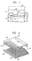
- Recording head to be used for the liquid jet recording method which utilizes heat energy for formation of a droplet to be discharged generally comprises on a base plate a discharging opening for discharging liquid; a liquid path communicated to said discharging opening having a portion at which heat energy to be utilized for discharging liquid acts on liquid; and an electrothermal transducer for generating said heat energy having a heat-generating resistor and a pair of electrodes connected to said heat-generating resistor, and has, for example, a structure shown in the schematic exploded perspective view in Fig. 2.
- the recording heads disclosed in Japanese Laid-open Patent Publication Nos. 55-128467 and 59-194866 comprises as a substrate 202 a heat-generating resistor 208 for generating heat energy, electrodes 209 and 210 for supplying electrical signals thereto and protective layers 213 and 214 laminated thereon for protecting these from liquid formed according to thin film forming technique, etc. and further comprises a liquid path 204 corresponding to the heat generating portion 201 of the heat-generating resistor 208 and a discharging outlet 217 formed on the substrate.
- the first protective layer 213 of the above protective layers 213 and 214 is provided as the layer primarily for maintaining insulation between the electrodes 209 and 210, while the second protective layer 214 as the layer for reinforcing liquid resistance and mechanical strength.
- the material for forming the second protective layer 214 there have been known in the art noble metals, (elements of the group VIII, etc.), high melting transition elements (elements of the groups III, IV, V, VI, etc.), alloys of these, or nitrides, borides, silicides, carbides of these metals or amorphous silicon, etc.
- the protective layer since the protective layer is subject to heat for gasification of liquid, cavitation shock created during droplet discharging and chemical action of liquid, it must be excellent in heat resistance, breaking resistance, liquid resistance, oxidation resistance, etc.
- the protective layer comprising nitrides, borides, silicides or carbides of the above metals
- the drawback of weak resistance to mechanical shock by cavitation shock which may be estimated to be due to the fact that the atomic bonds of such compounds are covalent bonding in nature.
- the present inventors in order to solve the above problems, have made various investigations about the material for formation of protective layer satisfying the requirements as described above and consequently found a material of protective layer which can satisfy all of the above requirements to accomplish the present invention.
- An object of the present invention is to provide a liquid jet recording head having a protective layer excellent in impact resistance, heat resistance, breaking resistance, liquid resistance, oxidation resistance, etc., a substrate for the said head and a liquid jet recording apparatus equipped with the said head.
- a liquid jet head comprising
- a substrate for 202 liquid jet recording head comprising
- a liquid jet apparatus equipped with the aforesaid liquid jet head.
- composition of the amorphous alloy to be used for formation of the second protective layer of the recording head of the present invention is represented by: M x (Fe 100-y-z Ni y Cr z ) 100-x wherein x is selected such that the alloy may be amorphous at the value x, for example, in the range of 10 to 70 atomic%, preferably 20 to 70 atomic%.
- y should be desirably made 5 to 30 atomic% and z 10 to 30 atomic%.
- M represents at least one selected from the group consisting of Ti, Zr, Hf, Nb, Ta and W. That is, these elements may be used either singly or in a plural number thereof, as desired.
- the amorphous alloy film represented by the above compositional formula has excellent properties as the constituent material of the second protective layer directly in contact with liquid such as heat resistance, corrosion resistance, mechanical strength, etc.
- the second protective layer (one shown by 214 in Fig. 1) by use of the amorphous alloy film
- conventional thin film deposition techniques, etc. may be applicable, but the sputtering method is suitable from the standpoint of obtaining readily a highly dense and strong amorphous alloy film.
- the second protactive layer should preferably have a film thickness of 0.1 to 5 ⁇ m, more preferably 0.2 to 3 ⁇ m.
- the constitution of the liquid jet recording head of the present invention except for the second protective layer 214 is not limited to the constitution shown in Fig. 1 and Fig. 2, but it may have any desired constitution.
- the direction of ink supply to the heat generating portion of the liquid path may be substantially same as or different from (e.g. forming substantially a right angle with) the direction of ink discharge.
- the layer of heat generating resistor and the layer of electrode may be provided in a reverse (upset) arrangement.
- liquid jet head may be of a so-called full line type which has discharge openings over the whole range of the recording width of receiving material.
- a heat-resistant insulating material such as SiO2, SiN, etc. may be employed suitably.
- the Al layer and the heat-generating resistor layer were subjected to patterning according to the photolithographic steps to a desired shape as shown in Fig. 2 to form an electrothermal transducer having a heat-generating resistor 208 and a pair of electrodes 209 and 210.
- SiO2 as the first protective layer 213 was laminated to a thickness of 1 ⁇ m by sputtering on the electrothermal transducer Ta50(Fe73Ni10Cr17)50 with a film thickness of 0.5 ⁇ m was laminated by sputtering on the SiO2 layer.
- a cover member of glass plate 203 having a groove which becomes the liquid path 204 was laminated through an epoxy type adhesive to obtain a liquid jet recording head having the constitution as shown in Fig. 1 and Fig. 2.
- a recording head was prepared in the same manner as in Example 1 except for forming by sputtering Ti25(Fe73Ni10Cr17)75 with a thickness of 2300 ⁇ as second protective layer.
- a recording head was prepared in the same manner as in Example 1 except for forming by sputtering Zr28(Fe73Ni10Cr17)72 with a thickness of 2000 ⁇ as the second protective layer.
- a recording head was prepared in the same manner as in Example 1 except for forming by sputtering Hf28(Fe73Ni10Cr17)72 with a thickness of 2100 ⁇ as the second protective layer.
- a recording head was prepared in the same manner as in Example 1 except for forming by sputtering Nb56(Fe68Ni11Cr21)44 with a thickness of 2400 ⁇ as the second protective layer.
- a recording head was prepared in the same manner as in Example 1 except for forming by sputtering W31(Fe68Ni11Cr21)69 with a thickness of 2100 ⁇ as the second protective layer.
- a recording head was prepared in the same manner as in Example 1 except for forming by sputtering Te32Ti18(Fe73Ni10Cr17)50 with a thickness of 2500 ⁇ as the second protective layer.
- a recording head was prepared in the same manner as in Example 1 except for forming by sputtering Nb28Zr20(Fe73Ni10Cr17)52 with a thickness of 2500 ⁇ as the second protective layer.
- a recording head was prepared in the same manner as in Example 1 except for forming by sputtering Hf35W22(Fe73Ni10Cr17)43 with a thickness of 2500 ⁇ as the second protective layer.
- a recording head was prepared in the same manner as in Example 1 except for forming by sputtering Ta40Ti13Nb11(Fe73Ni10Cr17)36 with a thickness of 2500 ⁇ as the second protective layer.
- a recording head was prepared in the same manner as in Example 1 except for forming by sputtering Ti9(Fe73Ni10Cr17)91 with a thickness of 2400 ⁇ as the second protective layer.
- the film having this composition was analyzed by X-ray diffractometry to be a polycrystalline film.
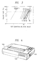
- Fig. 3 shows the Weibull plot of failure rate prepared from the results obtained. The time point when the resistance value of the heat-generating resistor exceeded 120% of the initial value was deemed as failure.
- a substrate for liquid jet head and a liquid jet head formed using the substrate of the present invention were prepared in the same manner as in Example 1 except for using SiN as the material of the first protective layer 213.
- a substrate for liquid jet head and a liquid jet head formed using the substrate having various excellent characteristics such as durability could be obtained.
- a substrate for liquid jet head and a liquid jet head formed using the substrate of the present invention were prepared in the same manner as in Example 2 except for additionally performing the steps of forming by spin coating a polyimide layer as a third protective layer on the second protective layer 214 and then removing the said layer on the heat generating portion.
- a substrate for liquid jet head and a liquid jet head formed using the substrate having various excellent characteristics such as durability could be obtained.
- the liquid path of the liquid jet head may be formed by initially forming the wall-forming member for liquid path using e.g. photosensitive resin and then attaching a top plate onto the wall-forming member.
- Fig. 4 is a schematic perspective view showing the appearance of the liquid jet apparatus equipped with the liquid jet head of the present invention. There are shown in Fig. 4 the main body of the apparatus 1000, power switch 1100 and operation panel 1200.
- the liquid jet head formed using the substrate for liquid jet head of the present invention has sufficient durability due to the use of an amorphous alloy film having the aforementioned specific composition and being excellent in heat resistance, liquid resistance and mechanical impact resistance as a protective layer, thereby having extremely long life and high durability.
Landscapes
- Particle Formation And Scattering Control In Inkjet Printers (AREA)
Claims (58)
- Flüssigkeitsstrahlkopf mit
einem elektrothermischen Wandler mit einem Wärmeerzeugungswiderstand (208) und einem an den Wärmeerzeugungswiderstand (208) elektrisch angeschlossenen Elektrodenpaar (209, 210),
einer Basisplatte (206) zum Halten des elektrothermischen Wandlers,
einer auf dem elektrothermischen Wandler vorgesehenen Schutzschicht (214), die im wesentlichen aus einer durch
Mx(Fe100-y-zNiyCrz)100-x
dargestellten amorphen Legierung besteht, worin M wenigstens ein unter Ti, Zr, Hf, Nb, Ta und W ausgewähltes Element ist und x 10 bis 70 Atom-% beträgt, und
einem auf der genannten Basisplatte gebildeten Flüssigkeitsweg (204), der dem zwischen dem Elektrodenpaar (209,210) gebildeten Wärmeerzeugungsteil (201) des elektrothermischen Wandlers entspricht und zur Abgabe der Flüssigkeit an eine Abgabeöffnung (217) angeschlossen ist. - Flüssigkeitsstrahlkopf nach Anspruch 1, bei dem die amorphe Legierung durch
Mx(Fe100-y-zNiyCrz)100-x
dargestellt wird, worin M wenigstens ein unter Ti, Zr, Hf, Nb, Ta und W ausgewähltes Element ist und x 20 bis 70 Atom-% beträgt. - Flüssigkeitsstrahlkopf nach Anspruch 1, bei dem die genannte amorphe Legierung durch
Mx(Fe100-y-zNiyCrz)100-x
dargestellt wird, worin M wenigstens ein unter Ti, Zr, Hf, Nb, Ta und W ausgewähltes Element ist und y 5 bis 30 Atom-% beträgt. - Flüssigkeitsstrahlkopf nach Anspruch 1, bei dem die genannte amorphe Legierung durch
Mx(Fe100-y-zNiyCrz)100-x
dargestellt wird, worin M wenigstens ein unter Ti, Zr, Hf, Nb, Ta und W ausgewähltes Element ist und z 10 bis 30 Atom-% beträgt. - Flüssigkeitsstrahlkopf nach Anspruch 1, bei dem die amorphe Legierung Ta₅₀(Fe₇₃Ni₁₀Cr₁₇)50 ist.
- Flüssigkeitsstrahlkopf nach Anspruch 1, bei dem die amorphe Legierung Ti₂₅(Fe₇₃Ni₁₀Cr₁₇)₇₅ ist.
- Flüssigkeitsstrahlkopf nach Anspruch 1, bei dem die amorphe Legierung Zr₂₈(Fe₇₃Ni₁₀Cr₁₇)₇₂ ist.
- Flüssigkeitsstrahlkopf nach Anspruch 1, bei dem die amorphe Legierung Hf₂₈(Fe₇₃Ni₁₀Cr₁)₇₂ ist.
- Flüssigkeitsstrahlkopf nach Anspruch 1, bei dem die amorphe Legierung Nb₅₆(Fe₆₈Ni₁₁Cr₂₁)₄₄ ist.
- Flüssigkeitsstrahlkopf nach Anspruch 1, bei dem die amorphe Legierung W₃₁(Fe₆₈Ni₁₁Cr₂₁)₆₉ ist.
- Flüssigkeitsstrahlkopf nach Anspruch 1, bei dem die amorphe Legierung Ta₃₂Ti₁₈(Fe₇₃Ni₁₀Cr₁₇)₅₀ ist.
- Flüssigkeitsstrahlkopf nach Anspruch 1, bei dem die amorphe Legierung Nb₂₈Zr₂₀(Fe₇₃Ni₁₀Cr₁₇)₅₂ ist.
- Flüssigkeitsstrahlkopf nach Anspruch 1, bei dem die amorphe Legierung Hf₃₅W₂₂(Fe₇₃Ni₁₀Cr₁₇)₄₃ ist.
- Flüssigkeitsstrahlkopf nach Anspruch 1, bei dem die amorphe Legierung Ta₄₀Ti₁₃Nb₁₁(Fe₇₃Ni₁₀Cr₁₇)₃₆ ist.
- Flüssigkeitsstrahlkopf nach Anspruch 1, bei dem die Dicke der genannten Schutzschicht (214) 0,1 bis 5 µm beträgt.
- Flüssigkeitsstrahlkopf nach Anspruch 1, bei dem die Dicke der genannten Schutzschicht (214) 0,2 bis 3 µm beträgt.
- Flüssigkeitsstrahlkopf nach Anspruch 1, bei dem der wärmeerzeugende Widerstand (208) zwischen der Basisplatte (206) und dem genannten Elektrodenpaar (209,210) vorgesehen ist.
- Flüssigkeitsstrahlkopf nach Anspruch 1, bei dem das genannte Elektrodenpaar (209,210) zwischen der Basisplatte (206) und dem genannten wärmeerzeugenden Widerstand (208) vorgesehen ist.
- Flüssigkeitsstrahlkopf nach Anspruch 1, bei dem der genannte elektrothermische Wandler die Wärme erzeugt, die für die Flüssigkeitsabgabe verwendet wird.
- Flüssigkeitsstrahlkopf nach Anspruch 1, bei dem die Richtung der Tintenabgabe aus der Abgabeöffnung (217) im wesentlichen die gleiche ist wie die Richtung der Tintenzuführung zu dem wärmeerzeugenden Teil (201).
- Flüssigkeitsstrahlkopf nach Anspruch 1, bei dem die Richtung der Tintenabgabe aus der Abgabeöffnung (217) von der Richtung der Tintenzuführung zu dem wärmeerzeugenden Teil (201) verschieden ist.
- Flüssigkeitsstrahlkopf nach Anspruch 21, bei dem die beiden Richtungen einen im wesentlichen rechten Winkel bilden.
- Flüssigkeitsstrahlkopf nach Anspruch 1, bei dem die genannte Abgabeöffnung (217) in einer Mehrzahl vorgesehen ist.
- Flüssigkeitsstrahlkopf nach Anspruch 1, bei dem die Abgabeöffnung (217) in einer der Breite des Aufzeichnungsmediums entsprechenden Mehrzahl vorgesehen ist.
- Flüssigkeitsstrahlkopf nach Anspruch 1, bei dem der Körper zur Bildung des genannten Flüssigkeitsweges (204) auf dem genannten Träger ein Abdeckkörper (203) mit einer Rinne für die Bildung des Flüssigkeitsweges ist.
- Flüssigkeitsstrahlkopf nach Anspruch 1, bei dem der Körper zur Bildung des Flüssigkeitsweges auf dem genannten Träger einen die Wandung für den Flüssigkeitsweg bildenden Wandbildungskörper und eine mit dem genannten Wandbildungskörper verbundene Kopfplatte umfaßt.
- Flüssigkeitsstrahlkopf nach Anspruch 26, bei dem der genannte Wandbildungskörper unter Benutzung eines lichtempfindlichen Harzes gebildet ist.
- Flüssigkeitsstrahlkopf nach Anspruch 1, bei dem eine andere Schutzschicht (213) zwischen der genannten Basisplatte (206) und der genannten Schutzschicht (214) vorgesehen ist.
- Flüssigkeitsstrahlkopf nach Anspruch 28, bei dem die andere Schutzschicht (213) aus einem wärmebeständigen Isoliermaterial besteht.
- Flüssigkeitsstrahlkopf nach Anspruch 29, bei dem das wärmebeständige Isoliermaterial SiO₂ ist.
- Flüssigkeitsstrahlkopf nach Anspruch 29, bei dem das wärmebeständige Isoliermaterial SiN ist.
- Flüssigkeitsstrahlkopf nach Anspruch 1 und 28, bei dem die Schuntzschichten anders als die genannten Schutzschichten (213,214) in dem genannten Flüssigkeitsstrahlkopf vorgesehen sind.
- Flüssigkeitsstrahlkopf nach Anspruch 32, bei dem die genannte andere Schutzschicht aus einem Polyimid besteht.
- Substrat (202) für einen Flüssigkeitsstrahlkopf mit
einem elektrothermischen Wandler mit einem Wärmeerzeugungswiderstand (208) und einem an den Wärmeerzeugungswiderstand elektrisch angeschlossenen Elektrodenpaar (209, 210),
einer Basisplatte (206) zum Halten des elektrothermischen Wandlers und
einer auf dem elektrothermischen Wandler vorgesehenen Schutzschicht (214), die im wesentlichen aus einer durch
Mx(Fe100-y-zNiyCrz)100-x
dargestellten amorphen Legierung besteht, worin M wenigstens ein unter Ti, Zr, Hf, Nb, Ta und W ausgewähltes Element ist und x 10 bis 70 Atom-% beträgt. - Substrat für einen Flüssigkeitsstrahlkopf nach Anspruch 34, bei dem die amorphe Legierung durch
Mx(Fe100-y-zNiyCrz)100-x
dargestellt wird, worin M wenigstens ein unter Ti, Zr, Hf, Nb, Ta und W ausgewähltes Element ist und x 20 bis 70 Atom-% beträgt. - Substrat für einen Flüssigkeitsstrahlkopf nach Anspruch 34, bei dem die amorphe Legierung durch
Mx(Fe100-y-zNiyCrz)100-x
dargestellt wird, worin M wenigstens ein unter Ti, Zr, Hf, Nb, Ta und W ausgewähltes Element ist und y 3 bis 30 Atom-% beträgt. - Substrat für einen Flüssigkeitstrahlkopf nach Anspruch 34, bei dem die amorphe Legierung durch
Mx(Fe100-y-zNiyCrz)100-x
dargestellt wird, worin M wenigstens ein unter Ti, Zr, Hf, Nb, Ta und W ausgewähltes Element ist und z 10 bis 30 Atom-% beträgt. - Substrat für einen Flüssigkeitsstrahlkopf nach Anspruch 34, bei dem die amorphe Legierung Ta₅₀(Fe₇₃Ni₁₀Cr₁₇)₅₀ ist.
- Substrat für einen Flüssigkeitsstrahlkopf nach Anspruch 34, bei dem die amorphe Legierung Ti₂₅(Fe₇₃Ni₁₀Cr₁₇)₇₅ ist.
- Substrat für einen Flüssigkeitsstrahlkopf nach Anspruch 34, bei dem die amorphe Legierung Zr₂₈(Fe₇₃NI₁₀Cr₁₇)₇₂ ist.
- Substrat für einen Flüssigkeitsstrahlkopf nach Anspruch 34, bei dem die amorphe Legierung Hf₂₈(Fe₇₃Ni₁₀Cr₁₇)₇₂ ist.
- Substrat für einen Flüssigkeitsstrahlkopf nach Anspruch 34, bei dem die amorphe Legierung Nb₅₆(Fe₆₈Ni₁₁Cr₂₁)₄₄ ist.
- Substrat für einen Flüssigkeitsstrahlkopf nach Anspruch 34, bei dem die amorphe Legierung W₃₁(Fe₆₈Ni₁₁Cr₂₁)₆₉ ist.
- Substrat für einen Flüssigkeitsstrahlkopf nach Anspruch 34, bei dem die amorphe Legierung Ta₃₂Ti₁₈(Fe₇₃Ni₁₀Cr₁₇)₅₀ ist.
- Substrat für einen Flüssigkeitsstrahlkopf nach Anspruch 34, bei dem die amorphe Legierung Nb₂₈Zr₂₀(Fe₇₃Ni₁₀Cr₁₇)₅₂ ist.
- Substrat für einen Flüssigkeitsstrahlkopf nach Anspruch 34, bei dem die amorphe Legierung Hf₃₅W₂₂(Fe₇₃Ni₁₀Cr₁₇)₄₃ ist.
- Substrat für einen Flüssigkeitsstrahlkopf nach Anspruch 34, bei dem die amorphe Legierung Ta₄₀Ti₁₃Nb₁₁(Fe₇₃Ni₁₀Cr₁₇)₃₆ ist.
- Substrat für einen Flüssigkeitsstrahlkopf nach Anspruch 34, bei dem die Dicke der genannten Schutzschicht 0,1 bis 5 µm beträgt.
- Substrat für einen Flüssigkeitsstrahlkopf nach Anspruch 34, bei dem die Dicke der genannten Schutzschicht 0,2 bis 3 µm beträgt.
- Substrat für einen Flüssigkeitsstrahlkopf nach Anspruch 34, bei dem der wärmeerzeugende Widerstand (208) zwischen der genannten Basisplatte (206) und dem genannten Elektrodenpaar (209,210) gebildet ist.
- Substrat für einen Flüssigkeitsstrahlkopf nach Anspruch 34, bei dem das Elektrodenpaar (209,210) zwischen der genannten Basisplatte (206) und dem genannten wärmeerzeugenden Widerstand (208) vorgesehen ist.
- Substrat für einen Flüssigkeitsstrahlkopf nach Anspruch 34, bei dem zwischen der genannten Basisplatte (206) und der genannten Schutzschicht (214) eine weitere Schutzschicht (213) vorgesehen ist.
- Substrat für einen Flüssigkeitsstrahlkopf nach Anspruch 34, bei dem die weitere Schutzschicht (213) aus einem wärmebe-ständigen Isoliermaterial besteht.
- Substrat für einen Flüssigkeitsstrahlkopf nach Anspruch 53, bei dem das wärmebeständige Isoliermaterial SiO₂ ist.
- Substrat für einen Flüssigkeitsstrahlkopf nach Anspruch 53, bei dem das wärmebeständige Isoliermaterial SiN ist.
- Substrat für einen Flüssigkeitsstrahlkopf nach Anspruch 34, bei dem die Schutzschichten anders als die genannten Schutzschichten (213, 214) in dem genannten Flüssigkeitsstrahlkopf vorgesehen sind.
- Substrat für einen Flüssigkeitsstrahlkopf nach Anspruch 56, bei dem die genannte andere Schutzschicht aus einem Polyimid besteht.
- Flüssigkeitsstrahlapparatur, die mit einem Flüssigkeitsstrahlkopf nach Anspruch 1 ausgerüstet ist.
Applications Claiming Priority (2)
| Application Number | Priority Date | Filing Date | Title |
|---|---|---|---|
| JP62303713A JP2683350B2 (ja) | 1987-12-01 | 1987-12-01 | 液体噴射記録ヘッド及び該ヘッド用基板 |
| JP303713/87 | 1987-12-01 |
Publications (3)
| Publication Number | Publication Date |
|---|---|
| EP0318981A2 EP0318981A2 (de) | 1989-06-07 |
| EP0318981A3 EP0318981A3 (en) | 1990-01-10 |
| EP0318981B1 true EP0318981B1 (de) | 1993-03-31 |
Family
ID=17924356
Family Applications (1)
| Application Number | Title | Priority Date | Filing Date |
|---|---|---|---|
| EP88120023A Expired - Lifetime EP0318981B1 (de) | 1987-12-01 | 1988-11-30 | Trägerschicht für Flüssigkeitsstrahlkopf und Flüssigkeitsstrahl vorrichtung, versehen mit solch einem Kopf |
Country Status (4)
| Country | Link |
|---|---|
| US (1) | US5057856A (de) |
| EP (1) | EP0318981B1 (de) |
| JP (1) | JP2683350B2 (de) |
| DE (1) | DE3879891T2 (de) |
Families Citing this family (12)
| Publication number | Priority date | Publication date | Assignee | Title |
|---|---|---|---|---|
| US5483270A (en) * | 1990-02-26 | 1996-01-09 | Canon Kabushiki Kaisha | Substrate for ink jet head |
| DE69315468T2 (de) * | 1992-04-16 | 1998-04-23 | Canon Kk | Tintenstrahlaufzeichnungskopf und Verfahren zu seiner Herstellung und Aufzeichnungsgerät damit versehen |
| JP3513270B2 (ja) * | 1995-06-30 | 2004-03-31 | キヤノン株式会社 | インクジェット記録ヘッド及びインクジェット記録装置 |
| US5901425A (en) | 1996-08-27 | 1999-05-11 | Topaz Technologies Inc. | Inkjet print head apparatus |
| JP3576888B2 (ja) | 1999-10-04 | 2004-10-13 | キヤノン株式会社 | インクジェットヘッド用基体、インクジェットヘッド及びインクジェット装置 |
| JP4666739B2 (ja) * | 1999-10-05 | 2011-04-06 | キヤノン株式会社 | インクジェット記録ヘッド用基体、インクジェット記録ヘッド、インクジェット記録ユニット、インクジェット記録装置、インクジェット記録ヘッド用基体の製造方法及びインクジェット記録ヘッドの製造方法 |
| JP2001171126A (ja) * | 1999-10-05 | 2001-06-26 | Canon Inc | 発熱抵抗素子を備えたインクジェットヘッド用基板と、それを用いるインクジェットヘッド、インクジェット装置及び記録方法 |
| JP3710364B2 (ja) | 2000-07-31 | 2005-10-26 | キヤノン株式会社 | インクジェットヘッド |
| JP3720689B2 (ja) | 2000-07-31 | 2005-11-30 | キヤノン株式会社 | インクジェットヘッド用基体、インクジェットヘッド、インクジェットヘッドの製造方法、インクジェットヘッドの使用方法およびインクジェット記録装置 |
| US20090049513A1 (en) * | 2007-08-17 | 2009-02-19 | Root Jason E | System and method for controlling a virtual environment of a user |
| CN102015311B (zh) | 2008-04-29 | 2015-05-20 | 惠普开发有限公司 | 打印装置 |
| JP5350205B2 (ja) * | 2009-12-16 | 2013-11-27 | キヤノン株式会社 | 液体吐出ヘッド用基板及び液体吐出ヘッド、およびその製造方法 |
Family Cites Families (14)
| Publication number | Priority date | Publication date | Assignee | Title |
|---|---|---|---|---|
| US4296421A (en) * | 1978-10-26 | 1981-10-20 | Canon Kabushiki Kaisha | Ink jet recording device using thermal propulsion and mechanical pressure changes |
| US4335389A (en) * | 1979-03-27 | 1982-06-15 | Canon Kabushiki Kaisha | Liquid droplet ejecting recording head |
| JPS5931942B2 (ja) * | 1979-03-27 | 1984-08-06 | キヤノン株式会社 | 液滴噴射記録装置 |
| DE3011919A1 (de) * | 1979-03-27 | 1980-10-09 | Canon Kk | Verfahren zur herstellung eines aufzeichnungskopfes |
| US4336548A (en) * | 1979-07-04 | 1982-06-22 | Canon Kabushiki Kaisha | Droplets forming device |
| JPS5833472A (ja) * | 1981-08-24 | 1983-02-26 | Canon Inc | 液体噴射記録ヘツド |
| JPS59106974A (ja) * | 1982-12-11 | 1984-06-20 | Canon Inc | 液体噴射記録ヘツド |
| JPH0624855B2 (ja) * | 1983-04-20 | 1994-04-06 | キヤノン株式会社 | 液体噴射記録ヘッド |
| JPS5913056A (ja) * | 1983-06-06 | 1984-01-23 | Res Inst Iron Steel Tohoku Univ | 高強度、耐疲労、耐全面腐食、耐孔食、耐隙間腐食、耐応力腐食割れ、耐水素脆性用アモルフアス鉄合金 |
| JPS60116452A (ja) * | 1983-11-30 | 1985-06-22 | Canon Inc | インクジェットヘッド |
| DE3446968A1 (de) * | 1983-12-26 | 1985-07-04 | Canon K.K., Tokio/Tokyo | Fluessigkeitsstrahlaufzeichnungskopf |
| US4756967A (en) * | 1985-05-25 | 1988-07-12 | Canon Kabushiki Kaisha | Magnetic recording medium |
| DE3618533A1 (de) * | 1985-06-10 | 1986-12-11 | Canon K.K., Tokio/Tokyo | Fluessigkeitsstrahl-aufzeichnungskopf und diesen fluessigkeitsstrahl-aufzeichnungskopf enthaltendes aufzeichnungssystem |
| DE3618596A1 (de) * | 1985-06-11 | 1986-12-11 | Canon K.K., Tokio/Tokyo | Fluessigkeitsstrahl-aufzeichnungskopf und diesen fluessigkeitsstrahl-aufzeichnungskopf enthaltendes aufzeichnungssystem |
-
1987
- 1987-12-01 JP JP62303713A patent/JP2683350B2/ja not_active Expired - Fee Related
-
1988
- 1988-11-30 DE DE8888120023T patent/DE3879891T2/de not_active Expired - Fee Related
- 1988-11-30 EP EP88120023A patent/EP0318981B1/de not_active Expired - Lifetime
-
1991
- 1991-02-07 US US07/652,364 patent/US5057856A/en not_active Expired - Lifetime
Also Published As
| Publication number | Publication date |
|---|---|
| DE3879891T2 (de) | 1993-08-05 |
| US5057856A (en) | 1991-10-15 |
| JP2683350B2 (ja) | 1997-11-26 |
| EP0318981A3 (en) | 1990-01-10 |
| EP0318981A2 (de) | 1989-06-07 |
| JPH01145158A (ja) | 1989-06-07 |
| DE3879891D1 (de) | 1993-05-06 |
Similar Documents
| Publication | Publication Date | Title |
|---|---|---|
| US4596994A (en) | Liquid jet recording head | |
| US4567493A (en) | Liquid jet recording head | |
| US4720716A (en) | Liquid jet recording head | |
| US5113203A (en) | Liquid jet head, substrate for said head and liquid jet apparatus having said head | |
| US4686544A (en) | Liquid jet recording head | |
| EP0318981B1 (de) | Trägerschicht für Flüssigkeitsstrahlkopf und Flüssigkeitsstrahl vorrichtung, versehen mit solch einem Kopf | |
| US4335389A (en) | Liquid droplet ejecting recording head | |
| US4694306A (en) | Liquid jet recording head with a protective layer formed by converting the surface of a transducer into an insulating material | |
| US4577202A (en) | Liquid jet recording head | |
| EP0286204A1 (de) | Grundplatte für Tintenstrahlaufzeichnungskopf | |
| JPS6338306B2 (de) | ||
| JPS60116452A (ja) | インクジェットヘッド | |
| GB2188004A (en) | Liquid jet recording head | |
| US5153610A (en) | Liquid jet recording head | |
| JPH0626887B2 (ja) | 液体噴射記録ヘツド | |
| KR100560717B1 (ko) | 잉크젯 헤드 기판, 잉크젯 헤드 및 잉크젯 헤드 기판의제조방법 | |
| JPS6131263A (ja) | 液体噴射記録ヘツド | |
| JPS60159060A (ja) | 液体噴射記録ヘツド | |
| JPH0512150B2 (de) | ||
| JPS60120067A (ja) | 液体噴射記録ヘツド | |
| JPS60116453A (ja) | 液体噴射記録ヘツド | |
| JPS60157869A (ja) | 液体噴射記録ヘツド | |
| JPS60137663A (ja) | 液体噴射記録ヘツド | |
| JPH02187354A (ja) | 液体噴射記録ヘッド用基体およびそれを用いた液体噴射記録ヘッド | |
| JPS60203452A (ja) | 液体噴射記録ヘツド |
Legal Events
| Date | Code | Title | Description |
|---|---|---|---|
| PUAI | Public reference made under article 153(3) epc to a published international application that has entered the european phase |
Free format text: ORIGINAL CODE: 0009012 |
|
| AK | Designated contracting states |
Kind code of ref document: A2 Designated state(s): DE FR GB IT |
|
| PUAL | Search report despatched |
Free format text: ORIGINAL CODE: 0009013 |
|
| AK | Designated contracting states |
Kind code of ref document: A3 Designated state(s): DE FR GB IT |
|
| 17P | Request for examination filed |
Effective date: 19900517 |
|
| 17Q | First examination report despatched |
Effective date: 19911106 |
|
| GRAA | (expected) grant |
Free format text: ORIGINAL CODE: 0009210 |
|
| AK | Designated contracting states |
Kind code of ref document: B1 Designated state(s): DE FR GB IT |
|
| REF | Corresponds to: |
Ref document number: 3879891 Country of ref document: DE Date of ref document: 19930506 |
|
| ET | Fr: translation filed | ||
| ITF | It: translation for a ep patent filed | ||
| ITTA | It: last paid annual fee | ||
| PLBE | No opposition filed within time limit |
Free format text: ORIGINAL CODE: 0009261 |
|
| STAA | Information on the status of an ep patent application or granted ep patent |
Free format text: STATUS: NO OPPOSITION FILED WITHIN TIME LIMIT |
|
| 26N | No opposition filed | ||
| REG | Reference to a national code |
Ref country code: GB Ref legal event code: IF02 |
|
| PGFP | Annual fee paid to national office [announced via postgrant information from national office to epo] |
Ref country code: FR Payment date: 20041109 Year of fee payment: 17 |
|
| PGFP | Annual fee paid to national office [announced via postgrant information from national office to epo] |
Ref country code: GB Payment date: 20041124 Year of fee payment: 17 |
|
| PGFP | Annual fee paid to national office [announced via postgrant information from national office to epo] |
Ref country code: DE Payment date: 20041125 Year of fee payment: 17 |
|
| PG25 | Lapsed in a contracting state [announced via postgrant information from national office to epo] |
Ref country code: IT Free format text: LAPSE BECAUSE OF NON-PAYMENT OF DUE FEES;WARNING: LAPSES OF ITALIAN PATENTS WITH EFFECTIVE DATE BEFORE 2007 MAY HAVE OCCURRED AT ANY TIME BEFORE 2007. THE CORRECT EFFECTIVE DATE MAY BE DIFFERENT FROM THE ONE RECORDED. Effective date: 20051130 Ref country code: GB Free format text: LAPSE BECAUSE OF NON-PAYMENT OF DUE FEES Effective date: 20051130 |
|
| PG25 | Lapsed in a contracting state [announced via postgrant information from national office to epo] |
Ref country code: DE Free format text: LAPSE BECAUSE OF NON-PAYMENT OF DUE FEES Effective date: 20060601 |
|
| GBPC | Gb: european patent ceased through non-payment of renewal fee |
Effective date: 20051130 |
|
| PG25 | Lapsed in a contracting state [announced via postgrant information from national office to epo] |
Ref country code: FR Free format text: LAPSE BECAUSE OF NON-PAYMENT OF DUE FEES Effective date: 20060731 |
|
| REG | Reference to a national code |
Ref country code: FR Ref legal event code: ST Effective date: 20060731 |