EP0318222B1 - Führungsöse für einen Sicherheitsgurt - Google Patents
Führungsöse für einen Sicherheitsgurt Download PDFInfo
- Publication number
- EP0318222B1 EP0318222B1 EP88310962A EP88310962A EP0318222B1 EP 0318222 B1 EP0318222 B1 EP 0318222B1 EP 88310962 A EP88310962 A EP 88310962A EP 88310962 A EP88310962 A EP 88310962A EP 0318222 B1 EP0318222 B1 EP 0318222B1
- Authority
- EP
- European Patent Office
- Prior art keywords
- slot
- guide ring
- seat belt
- ring assembly
- body member
- Prior art date
- Legal status (The legal status is an assumption and is not a legal conclusion. Google has not performed a legal analysis and makes no representation as to the accuracy of the status listed.)
- Expired - Lifetime
Links
- 230000000452 restraining effect Effects 0.000 claims description 7
- 239000000463 material Substances 0.000 claims description 2
- 239000004033 plastic Substances 0.000 claims description 2
- 229920003023 plastic Polymers 0.000 claims description 2
- 238000013459 approach Methods 0.000 description 2
- 239000011521 glass Substances 0.000 description 1
- 238000009499 grossing Methods 0.000 description 1
- 230000002401 inhibitory effect Effects 0.000 description 1
- 230000005764 inhibitory process Effects 0.000 description 1
- 238000003780 insertion Methods 0.000 description 1
- 230000037431 insertion Effects 0.000 description 1
- 239000002991 molded plastic Substances 0.000 description 1
Images
Classifications
-
- B—PERFORMING OPERATIONS; TRANSPORTING
- B60—VEHICLES IN GENERAL
- B60R—VEHICLES, VEHICLE FITTINGS, OR VEHICLE PARTS, NOT OTHERWISE PROVIDED FOR
- B60R22/00—Safety belts or body harnesses in vehicles
- B60R22/18—Anchoring devices
- B60R22/24—Anchoring devices secured to the side, door, or roof of the vehicle
-
- Y—GENERAL TAGGING OF NEW TECHNOLOGICAL DEVELOPMENTS; GENERAL TAGGING OF CROSS-SECTIONAL TECHNOLOGIES SPANNING OVER SEVERAL SECTIONS OF THE IPC; TECHNICAL SUBJECTS COVERED BY FORMER USPC CROSS-REFERENCE ART COLLECTIONS [XRACs] AND DIGESTS
- Y10—TECHNICAL SUBJECTS COVERED BY FORMER USPC
- Y10T—TECHNICAL SUBJECTS COVERED BY FORMER US CLASSIFICATION
- Y10T24/00—Buckles, buttons, clasps, etc.
- Y10T24/47—Strap-end-attaching devices
- Y10T24/4764—Ring-loop
Definitions
- the present invention relates generally to guide rings for automotive safety belt systems and more particularly to improvements in the anti-twist features for such guide rings.
- a guide ring commonly referred to as a "D" ring, is normally positioned at or near the roof or supporting pillar positioned just rearward of the occupants. The seat belt is fed through this ring from the retractor to the seat belt's tongue or other locking element.
- This guide ring is used both to properly position the shoulder belt across the front seat occupant and to guide the passage of the belt during deployment and retraction.
- An example of such slot designs is that shown in U.S. 4,023,826, in which a slot is profiled to resist the tendency of the belt to twist and jam under certain side loads.
- Another approach to providing an anti-twist feature is that shown in U.S. 4,142,274 in which a simple slot is overlaid with a portion of the guide ring.
- a guide ring assembly for controlling the movement of an automobile seat belt from its occupant restraining position to its stored position in a seat belt retractor
- the guide ring assembly comprising, a body member including a mounting portion for pivotally mounting the body member on an interior portion of the automobile and a guide portion having a first slot formed therethrough substantially alignable with the path of the seat belt to the retractor, the first slot being closely sized to the thickness of the seat belt, characterised by a cover member carried on the body member in overlying fashion and having an edge portion positioned adjacent the exit of the slot.
- the cover member is formed of plastics material and its edge portion which acts as a secondary anti-twist means extends laterally substantially over the width of the first slot.
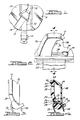
- a guide ring assembly 10 is illustrated as being mounted on an interior portion of a pillar 12 of an automobile, such as the central pillar usually referred to as the "B" pillar of the automobile between front and rear panes of glass 14, 16 respectively.
- the seat belt 18 of the system has a portion 20 extending forwardly to restrain the occupant and a portion 22 extending adjacent the pillar 12 to a floor mounted retractor assembly, shown schematically at 11, from which it has been paid out, usually through agency of a spring loaded spool.
- the retractor assembly 11 serves to wind up the belt 18 and the guide ring assembly 10 assumes a more nearly vertical position as is illustrated in Figure 2. Because of the flexibility of the belt 18, it is during this operation that the twisting or roping of the belt 18 may occur.
- the guide ring assembly 10 comprises a body 24 and a cover member 26.
- the body 24 includes a mounting portion 28 through which is formed an aperture 30 for receiving a fastener, not shown, by which the guide ring assembly 10 may be fixed for pivotal movement to the pillar 12.
- Below the mounting portion 28 extends a guide portion 32 at an angle extending away from the face of the pillar 12 towards the interior of the automobile.
- a plurality of slots are formed through the guide portion 32 of the body 24.
- Uppermost as viewed in Figure 4 is a generally horizontally extending retaining slot 34 for receiving a catch portion 36 of the cover member 26.
- a profile slot 38 which is formed as a substantially horizontal slot having enlarged end portions, as shown at 40 in Figure 2.
- the enlarged portions 40 guide and restrain the movement of the lateral edges of the belt 18 when it is in the restraining position, as shown in Figure 1, to resist twisting or roping of the belt 18 as its path changes from vertical as it leaves the retractor assembly 11 to diagonal as it crosses the front seat occupant of the automobile.
- the remaining lowermost slot 42 formed through guide portion 32 of the body 24 provides the primary means for inhibiting twisting of the belt 18 when the belt is doffed by the vehicle occupant.
- the cover member 26 is preferably formed as a moulded plastics part of cup-like configuration. It has a channel portion 44 formed to the interior of its upper surface including a wall portion 46 which engages a shoulder 47 formed at the upper end of the mounting portion 28 of the body 24. Spaced inwardly from the mounting portion 28, the wall 48 of the cover member defines with the mounting portion 28 a space 50 for enclosing the mounting fastener. At the lower terminus of the wall 48, a leg 52 terminating in the catch 36 extends perpendicularly for insertion into the retaining slot 34.
- the portion 22 adjacent the pillar 12 moves toward the retractor assembly 11, typically under the influence of a conventional spring-loaded spool mechanism.
- the portion 20 of the belt 18 extended towards the occupant passes through the slot 42 which is closely sized to the thickness of the belt 18, as may be seen in Figure 4, to resist the tendency to twist.
- the slot 42 is arranged to be alignable in the path of the seat belt 18 as it is drawn to the retractor assembly 11. Under the modest loads imposed by a typical seat belt retractor assembly 11, the smoothing action of the slot 42 is in most cases sufficient to prevent twisting.
- edge 56 is preferably sized to extend to a width greater than that of the seat belt 18 as may be seen in Figure 2.
Landscapes
- Engineering & Computer Science (AREA)
- Mechanical Engineering (AREA)
- Automotive Seat Belt Assembly (AREA)
Claims (6)
- Führungsringeinheit zur Kontrolle der Bewegung eines Autosicherheitsgurtes (18) aus seiner Insassenrückhalteposition in seine Ruheposition in einer Sicherheitsgurtaufrollvorrichtung (11), wobei die Führungsringeinheit (10) ein Körperelement (24) mit einem Montageabschnitt (28) zur drehbaren Montage des Körperelementes (24) an einem Innenabschnitt des Automobils und einen Führungsabschnitt (32) mit einem durchgehenden ersten Schlitz (42) umfaßt, der sich im wesentlichen entsprechend dem Weg des Sicherheitsgurtes (18) zur Aufrollvorrichtung (11) hin ausrichten läßt, wobei der erste Schlitz (42) in seinen Abmessungen in enger Passung der Dicke des Sicherheitsgurtes (18) angepasst ist, gekennzeichnet durch ein Abdeckungselement (26), das vom Körperelement (24) in überlagernder Ausführung getragen wird und einen Kantenabschnitt (56) aufweist, der in der Nähe des Ausgangs des Schlitzes (42) angeordnet ist.
- Führungsringeinheit nach Anspruch 1, wobei das Abdeckungselement (26) aus Kunststoff besteht.
- Führungsringeinheit nach Anspruch 1 oder 2, wobei sich der Kantenabschnitt (56) seitlich im wesentlichen über die Breite des ersten Schlitzes (42) erstreckt.
- Führungsringeinheit nach einem der vorstehenden Ansprüche, weiterhin umfassend einen Ansatzabschnitt, der integraler Bestandteil einer Wand des Abdeckungselementes (26) ist und sich in Richtung auf das Körperelement (24) erstreckt, sowie einen durchgehenden zweiten Schlitz (34), der im Körperelementführungsabschnitt (32) in der Nähe des ersten Schlitzes (42) zur Aufnahme des Ansatzabschnittes ausgebildet ist.
- Führungsringeinheit nach Anspruch 6, weiterhin umfassend einen Auffangabschnitt (36), der in der Nähe des freien Endes des Ansatzabschnittes ausgebildet ist.
- Führungsringeinheit nach Anspruch 4 oder 5, wobei das Körperelement (24) weiterhin einen Profilschlitz (38) mit vergrößerten Endöffnungen (40) in durchgehender Ausführung in einem Abschnitt des Körperelementes (24) mit Abstand zum ersten Schlitz (42) und mit entsprechender Ausrichtung zum Weg des Sicherheitsgurtes (18) entfernt von der Aufrollvorrichtung (11) umfaßt.
Applications Claiming Priority (2)
| Application Number | Priority Date | Filing Date | Title |
|---|---|---|---|
| US07/125,978 US4861070A (en) | 1987-11-27 | 1987-11-27 | Seatbelt guide ring with anti-twist feature |
| US125978 | 1993-09-23 |
Publications (2)
| Publication Number | Publication Date |
|---|---|
| EP0318222A1 EP0318222A1 (de) | 1989-05-31 |
| EP0318222B1 true EP0318222B1 (de) | 1992-07-15 |
Family
ID=22422371
Family Applications (1)
| Application Number | Title | Priority Date | Filing Date |
|---|---|---|---|
| EP88310962A Expired - Lifetime EP0318222B1 (de) | 1987-11-27 | 1988-11-21 | Führungsöse für einen Sicherheitsgurt |
Country Status (4)
| Country | Link |
|---|---|
| US (1) | US4861070A (de) |
| EP (1) | EP0318222B1 (de) |
| CA (1) | CA1319350C (de) |
| DE (1) | DE3872841T2 (de) |
Families Citing this family (10)
| Publication number | Priority date | Publication date | Assignee | Title |
|---|---|---|---|---|
| US5257820A (en) * | 1990-05-16 | 1993-11-02 | Takata Corporation | Slip anchor for seat belt |
| US5175248A (en) * | 1990-06-04 | 1992-12-29 | Sartomer Company, Inc. | Process for the removal of n-vinylcarbazole from poly(n-vinylcarbazole) |
| WO1995023011A2 (en) * | 1994-02-17 | 1995-08-31 | Alliedsignal Inc. | Seat belt web guide |
| US5937491A (en) * | 1997-10-30 | 1999-08-17 | Yung Ta Hardware & Plastic Co., Ltd. | Metal hanger ring |
| DE19810380A1 (de) * | 1998-03-10 | 1999-09-16 | Bayerische Motoren Werke Ag | Umlenkbeschlag für einen Sicherheitsgurt |
| US6250684B1 (en) | 1998-10-01 | 2001-06-26 | Trw Vehicle Safety Systems Inc. | D-ring/roller assembly for supporting seat belt webbing in a vehicle |
| CN101309822B (zh) * | 2003-08-26 | 2012-04-18 | 奥托里夫发展有限公司 | 带单件式包覆部的安全带变向元件 |
| JP4692515B2 (ja) * | 2007-06-01 | 2011-06-01 | トヨタ自動車株式会社 | ショルダアンカ装置 |
| US20090078811A1 (en) * | 2007-09-21 | 2009-03-26 | Roger Dick | Anti-twist device |
| US20190256039A1 (en) * | 2018-02-20 | 2019-08-22 | GM Global Technology Operations LLC | Systems and methods for a self-aligning restraint system |
Family Cites Families (10)
| Publication number | Priority date | Publication date | Assignee | Title |
|---|---|---|---|---|
| GB1280153A (en) * | 1968-05-07 | 1972-07-05 | Teleflex Ltd Formerly Known As | Improvements in pillar loops |
| DE2228127B2 (de) * | 1972-06-09 | 1976-09-09 | Carl Stahl, Gurt- und Bandweberei, 7922 Herbrechtingen;Kühl, Hans, Dipl.-Ing., 7310 Plochingen | Umlenkbeschlag fuer sicherheitsgurte |
| SE384972B (sv) * | 1973-06-13 | 1976-05-31 | T R Silen | Anordning for inriktning av en rem, sasom ett rullbelte i ett motorfordon |
| DE2813533A1 (de) * | 1978-03-29 | 1979-10-04 | Bayerische Motoren Werke Ag | Leitvorrichtung fuer eine gurtumlenkung fuer sicherheitsgurte mit gurtaufwickler in kraftfahrzeugen |
| DE2915988C2 (de) * | 1979-04-20 | 1983-01-05 | Daimler-Benz Ag, 7000 Stuttgart | Leitvorrichtung für von einer Vorratsrolle eines Sicherheitsgurtsystems abspulbares und auf diese aufspulbares Gurtband |
| DE2945174C2 (de) * | 1979-11-08 | 1983-11-10 | Repa Feinstanzwerk Gmbh, 7071 Alfdorf | Umlenkbeschlag für den Sicherheitsgurt eines Rückhaltesystems |
| DE3134338A1 (de) * | 1981-08-31 | 1983-03-10 | Alois 6685 Schiffweiler Bost | "dreipunkt-sicherheitsgurt" |
| DE3144527A1 (de) * | 1981-11-10 | 1983-05-19 | Klippan GmbH, Sicherheitsgeräte, 2000 Norderstedt | Vorrichtung zur fuehrung oder umlenkung eines bandes, insbesondere fuer einen sicherheitsgurt in einem kraftfahrzeug |
| DE3505928A1 (de) * | 1985-02-21 | 1986-08-28 | Bayerische Motoren Werke AG, 8000 München | Umlenkbeschlag fuer sicherheitsgurte |
| US4642853A (en) * | 1986-03-31 | 1987-02-17 | General Motors Corporation | Seat belt guide loop |
-
1987
- 1987-11-27 US US07/125,978 patent/US4861070A/en not_active Expired - Fee Related
-
1988
- 1988-10-25 CA CA000581128A patent/CA1319350C/en not_active Expired - Fee Related
- 1988-11-21 EP EP88310962A patent/EP0318222B1/de not_active Expired - Lifetime
- 1988-11-21 DE DE8888310962T patent/DE3872841T2/de not_active Expired - Fee Related
Also Published As
| Publication number | Publication date |
|---|---|
| DE3872841T2 (de) | 1993-01-07 |
| DE3872841D1 (de) | 1992-08-20 |
| EP0318222A1 (de) | 1989-05-31 |
| US4861070A (en) | 1989-08-29 |
| CA1319350C (en) | 1993-06-22 |
Similar Documents
| Publication | Publication Date | Title |
|---|---|---|
| US5364170A (en) | Seat belt webbing guide | |
| US5054815A (en) | Shoulder belt comfort mechanism | |
| EP0608860B1 (de) | Rückhalte- und Aufprallschutzsitz für Kinder | |
| EP0318222B1 (de) | Führungsöse für einen Sicherheitsgurt | |
| US4551889A (en) | Low friction self-locking adjust tongue | |
| US6969022B2 (en) | Seat belt retractor | |
| US5222278A (en) | Tongue assembly | |
| US9988013B2 (en) | Grip tongue latch plate for seatbelt | |
| EP0335936B1 (de) | Aufrollvorrichtung für sicherheitsgurte | |
| EP1405777A1 (de) | Aufroller | |
| JP3598311B2 (ja) | ローピング防止ラッチプレート | |
| GB1601104A (en) | Safety restraint apparatus | |
| US20200017063A1 (en) | Three-point seat belt with additional safety features | |
| US3869097A (en) | Webbing slot for seat belt retractor housing | |
| US4087118A (en) | Safety seat belt system | |
| US5080440A (en) | Vehicle seat belt winding system having angled guide wire | |
| US4179136A (en) | Seat belt system | |
| US4372579A (en) | Passive seat belt arrangement for a vehicle | |
| KR0134236Y1 (ko) | 자동차의 뒷좌석 시트벨트 하우징 설치구조 | |
| GB2035049A (en) | Passive restraint harness | |
| EP0790159A1 (de) | Dreipunkt-Sicherheitsgurtsystem für Fahrzeuge | |
| US4730874A (en) | Seat for vehicle | |
| US20040108708A1 (en) | Webbing insertion member | |
| KR100229743B1 (ko) | 자동차의 시트 벨트 텅 플레이트 | |
| KR20000040375A (ko) | 자동차용 시트벨트의 웨빙 가이드 |
Legal Events
| Date | Code | Title | Description |
|---|---|---|---|
| PUAI | Public reference made under article 153(3) epc to a published international application that has entered the european phase |
Free format text: ORIGINAL CODE: 0009012 |
|
| AK | Designated contracting states |
Kind code of ref document: A1 Designated state(s): DE FR GB |
|
| 17P | Request for examination filed |
Effective date: 19891028 |
|
| 17Q | First examination report despatched |
Effective date: 19910604 |
|
| GRAA | (expected) grant |
Free format text: ORIGINAL CODE: 0009210 |
|
| AK | Designated contracting states |
Kind code of ref document: B1 Designated state(s): DE FR GB |
|
| REF | Corresponds to: |
Ref document number: 3872841 Country of ref document: DE Date of ref document: 19920820 |
|
| ET | Fr: translation filed | ||
| PLBE | No opposition filed within time limit |
Free format text: ORIGINAL CODE: 0009261 |
|
| STAA | Information on the status of an ep patent application or granted ep patent |
Free format text: STATUS: NO OPPOSITION FILED WITHIN TIME LIMIT |
|
| 26N | No opposition filed | ||
| REG | Reference to a national code |
Ref country code: GB Ref legal event code: 746 Effective date: 19931013 |
|
| PGFP | Annual fee paid to national office [announced via postgrant information from national office to epo] |
Ref country code: GB Payment date: 19981029 Year of fee payment: 11 |
|
| PGFP | Annual fee paid to national office [announced via postgrant information from national office to epo] |
Ref country code: FR Payment date: 19981110 Year of fee payment: 11 |
|
| PGFP | Annual fee paid to national office [announced via postgrant information from national office to epo] |
Ref country code: DE Payment date: 19981128 Year of fee payment: 11 |
|
| PG25 | Lapsed in a contracting state [announced via postgrant information from national office to epo] |
Ref country code: GB Free format text: LAPSE BECAUSE OF NON-PAYMENT OF DUE FEES Effective date: 19991121 |
|
| GBPC | Gb: european patent ceased through non-payment of renewal fee |
Effective date: 19991121 |
|
| PG25 | Lapsed in a contracting state [announced via postgrant information from national office to epo] |
Ref country code: FR Free format text: LAPSE BECAUSE OF NON-PAYMENT OF DUE FEES Effective date: 20000731 |
|
| PG25 | Lapsed in a contracting state [announced via postgrant information from national office to epo] |
Ref country code: DE Free format text: LAPSE BECAUSE OF NON-PAYMENT OF DUE FEES Effective date: 20000901 |
|
| REG | Reference to a national code |
Ref country code: FR Ref legal event code: ST |